


3COM SuperStack II PS Hub 40, PS Hub 50, SuperStack II 3C16405, SuperStack II 3C16406, SuperStack II 3C16450 User Manual
SuperStack® II PS Hub
® |
User Guide |
|
3C16405 — PS Hub 40 12-port
3C16406 — PS Hub 40 24-port
3C16450 — PS Hub 50 24-port
http://www.3com.com/
Part No. DUA1640-5AAA02
Published July 1997
3Com Corporation 5400 Bayfront Plaza Santa Clara, California 95052-8145
© 3Com Technologies, 1997. All rights reserved. No part of this documentation may be reproduced in any form or by any means or used to make any derivative work (such as translation, transformation, or adaptation) without permission from 3Com Technologies.
3Com Technologies reserves the right to revise this documentation and to make changes in content from time to time without obligation on the part of 3Com Technologies to provide notification of such revision or change.
3Com Technologies provides this documentation without warranty of any kind, either implied or expressed, including, but not limited to, the implied warranties of merchantability and fitness for a particular purpose. 3Com may make improvements or changes in the product(s) and/or the program(s) described in this documentation at any time.
UNITED STATES GOVERNMENT LEGENDS:
If you are a United States government agency, then this documentation and the software described herein are provided to you subject to the following restricted rights:
For units of the Department of Defense:
Restricted Rights Legend: Use, duplication or disclosure by the Government is subject to restrictions as set forth in subparagraph (c) (1) (ii) for restricted Rights in Technical Data and Computer Software clause at 48 C.F.R. 52.227-7013. 3Com Centre, Boundary Way, Maylands Park South, Hemel Hempstead, Herts, HP2 7YU, UK.
For civilian agencies:
Restricted Rights Legend: Use, reproduction or disclosure is subject to restrictions set forth in subparagraph
(a) through (d) of the Commercial Computer Software - Restricted Rights Clause at 48 C.F.R. 52.227-19 and the limitations set forth in 3Com Corporation’s standard commercial agreement for the software. Unpublished rights reserved under the copyright laws of the United States.
If there is any software on removable media described in this documentation, it is furnished under a license agreement included with the product as a separate document, in the hard copy documentation, or on the removable media in a directory file named LICENSE.TXT. If you are unable to locate a copy, please contact 3Com and a copy will be provided to you.
Unless otherwise indicated, 3Com registered trademarks are registered in the United States and may or may not be registered in other countries.
3Com, LANplex, LinkBuilder, NETBuilder II, SmartAgent, SuperStack and Transcend are registered trademarks of 3Com Corporation. CoreBuilder and FMS are trademarks of 3Com Corporation. 3ComFacts is a service mark of 3Com Corporation.
CompuServe is a registered trademark of CompuServe, Inc. Windows and Windows NT are registered trademarks of Microsoft. IPX is a registered trademark of Ideographix, Inc. Netscape Navigator is a trademark of Netscape Communications Corporation.
Other brand and product names may be registered trademarks or trademarks of their respective holders.
Environmental Statement
It is 3Com’s policy to be environmentally friendly in all its operations. This manual is printed on paper that comes from sustainable, managed European forests. The production process for making the pulp has a reduced AOX level (adsorbable organic halogen) resulting in elemental chlorine free paper.
The paper is fully bio-degradable and recyclable.
ii

CONTENTS
IMPORTANT SAFETY INFORMATION
L’INFORMATION DE SÉCURITÉ IMPORTANTE
WICHTIGE SICHERHEITSHINWEISE
ABOUT THIS GUIDE
|
Introduction |
1 |
|
|
|
|
How to Use This Guide |
2 |
|
|
|
|
Conventions |
2 |
|
|
|
|
|
|
|
|
|
1 ABOUT THE PS HUB |
|
|
|
||
|
Introduction |
1-1 |
|
|
|
|
Features |
1-2 |
|
|
|
|
How You Can Use the PS Hub 1-4 |
|
|||
|
Building Up a Network |
1-4 |
|
|
|
|
Expanding an Existing Network |
1-5 |
|||
|
Migrating to Higher Performance |
1-6 |
|||
|
Workgroups |
1-7 |
|
|
|
|
What Are Workgroups? 1-7 |
|
|
||
|
Segments and Port Switching |
1-8 |
|
||
|
Workgroup Example |
1-11 |
|
|
|
|
|
|
|
||
2 HOW THE PS HUBS DIFFER |
|
|
|||
|
Overview |
2-1 |
|
|
|
|
PS Hub 40 |
2-2 |
|
|
|
|
PS Hub 50 |
2-2 |
|
|
|
|
Segment Switch 2-2 |
|
|
|
|
|
PS Hub 50 Transceiver Module Slot |
2-6 |
|||

3 USING THE PS HUB
|
LEDs and Ports |
3-1 |
|
|
|
|
|
|
|
Before You Start |
3-4 |
|
|
|
|
|
|
|
What Other Equipment Is Needed? 3-4 |
|
||||||
|
Positioning the PS Hub |
3-6 |
|
|
|
|||
|
Using the Rubber Feet |
3-6 |
|
|
|
|||
|
Using the Labels |
3-7 |
|
|
|
|
|
|
|
Rack and Wall Mounting |
3-8 |
|
|
|
|||
|
Rack Mounting |
3-8 |
|
|
|
|
|
|
|
Wall Mounting |
3-9 |
|
|
|
|
|
|
|
Connecting Workstations to Your Hub |
3-11 |
|
|||||
|
Using Transceiver Modules 3-12 |
|
|
|||||
|
Connecting PS Hubs Together (Stacking) |
3-12 |
|
|||||
|
About Cascade Cables |
3-13 |
|
|
|
|||
|
Using Cascade Cables |
|
3-14 |
|
|
|
||
|
Using Hot Swap Cascade Units |
3-15 |
|
|||||
|
Connecting Different Hubs and Stacks to Your Hub |
3-16 |
||||||
|
Powering On the Units |
3-17 |
|
|
|
|||
|
Spot Checks |
3-17 |
|
|
|
|
|
|
|
|
|
|
|
|
|
||
4 LOAD BALANCING |
|
|
|
|
|
|||
|
Overview 4-1 |
|
|
|
|
|
|
|
|
How Does Load Balancing Work? 4-2 |
|
||||||
|
Using an External Switch |
4-3 |
|
|
|
|||
|
Performing Load Balancing |
4-3 |
|
|
|
|||
|
|
|
|
|
||||
5 MANAGING THE PS HUB |
|
|
|
|||||
|
Introduction |
5-1 |
|
|
|
|
|
|
|
Why Manage Your Stack? 5-2 |
|
|
|
||||
|
How You Can Manage Your Stack |
5-3 |
|
|
||||
|
Command Line Interface |
5-3 |
|
|
|
|||
|
Web Interface |
5-3 |
|
|
|
|
|
|
|
SNMP Network Management |
5-4 |
|
|
||||
|
Methods of Management |
5-5 |
|
|
|
|||
|
Requirements for Managing Over the Network |
5-6 |
||||||
|
IP Addresses |
5-7 |
|
|
|
|
|
|
iv
|
Command Line Interface (CLI) |
5-8 |
|
||||
|
Through the Console Port |
5-8 |
|
||||
|
Over the Network |
5-11 |
|
|
|||
|
Web Interface |
5-12 |
|
|
|
|
|
|
Through the Console Port |
5-12 |
|
||||
|
Over the Network |
5-12 |
|
|
|||
|
Which Web Browsers are Supported? 5-12 |
|
|||||
|
Quick Config Manager |
5-13 |
|
|
|||
|
Through the Console Port |
5-13 |
|
||||
|
Over the Network |
5-14 |
|
|
|||
|
|
|
|||||
6 USING THE COMMAND LINE INTERFACE |
|
||||||
|
Accessing the CLI |
6-2 |
|
|
|
|
|
|
Initial Access |
6-2 |
|
|
|
|
|
|
Logging On |
6-2 |
|
|
|
|
|
|
Logging Off |
6-3 |
|
|
|
|
|
|
Using the CLI Menus |
6-4 |
|
|
|
||
|
CLI Menu Structure |
6-4 |
|
|
|||
|
Navigating the Menus and Entering Commands |
6-5 |
|||||
|
Quick Guide to the Commands |
6-6 |
|
||||
|
Commands |
6-7 |
|
|
|
|
|
|
Changing the Password |
6-7 |
|
||||
|
Setting the IP Configuration |
6-8 |
|
||||
|
Viewing the Configuration |
6-9 |
|
||||
|
Resetting the Stack |
6-10 |
|
|
|||
|
Initializing the Stack |
6-11 |
|
|
|||
|
Configuring Another Unit in the Stack 6-11 |
|
|||||
|
Enabling and Disabling RMON Filter Capture |
6-12 |
|||||
|
|
||||||
7 MANAGEMENT USING THE WEB INTERFACE |
|||||||
|
Accessing the Web Interface |
7-1 |
|
||||
|
About the Web Interface |
7-4 |
|
|
|||
|
General Components |
7-4 |
|
|
|||
|
Page Components |
7-6 |
|
|
|||
|
Web Interface Map |
7-6 |
|
|
|||
v
|
Using the Web Interface |
7-7 |
|
|
|||
|
Unit View and Unit Pages |
7-8 |
|
||||
|
User Access Levels |
7-9 |
|
|
|||
|
Exiting the Web Interface |
7-9 |
|
||||
|
Online Help System and Documentation |
7-9 |
|||||
|
Unit Pages |
7-10 |
|
|
|
|
|
|
Unit View |
7-10 |
|
|
|
|
|
|
Unit Status 7-11 |
|
|
|
|||
|
Management Address |
7-12 |
|
||||
|
Port Setup |
7-13 |
|
|
|
|
|
|
Console Port Configuration |
7-14 |
|
||||
|
Segment Configuration |
7-15 |
|
||||
|
Switch Configuration |
7-16 |
|
||||
|
Permanent Address Management 7-16 |
||||||
|
Management Settings Pages |
7-17 |
|
||||
|
Documentation |
|
7-17 |
|
|
|
|
|
Getting Started |
|
7-18 |
|
|
|
|
|
Password Setting |
7-19 |
|
|
|||
|
System Name |
7-19 |
|
|
|
||
|
Configuration Pages |
7-20 |
|
|
|||
|
Initialize |
7-20 |
|
|
|
|
|
|
Load Balancing |
7-20 |
|
|
|
||
|
Reset 7-20 |
|
|
|
|
|
|
|
Resilient Links |
7-21 |
|
|
|
||
|
Add Resilient Link |
7-23 |
|
|
|||
|
Software Upgrade |
7-24 |
|
|
|||
|
Health Pages |
7-25 |
|
|
|
|
|
|
Segment Graph |
|
7-25 |
|
|
|
|
|
|
|
|
|
|||
8 PROBLEM SOLVING |
|
|
|
||||
|
Isolating a Problem |
|
8-1 |
|
|
|
|
|
Solving Problems With the Hub |
8-2 |
|
||||
|
Solving Problems With the Command Line Interface 8-3 |
||||||
|
Solving Problems With the Web Interface |
8-4 |
|||||
Solving Problems With an SNMP Network Management Application 8-5
vi

A |
DIMENSIONS, STANDARDS AND CABLING |
|||
|
Dimensions and Operating Environment A-1 |
|||
|
BABT Approval (for U.K. Users Only) A-1 |
|||
|
Standards |
A-2 |
|
|
|
Cabling |
A-3 |
|
|
|
10BASE-T Cable |
A-3 |
||
|
Console Cable |
A-4 |
|
|
|
Modem Cable |
A-5 |
|
|
|
Cascade Connections |
A-6 |
||
|
Management Settings |
A-6 |
||
B |
|
|||
MANAGEMENT USING QUICK CONFIG MANAGER |
||||
|
Installing Quick Config Manager and the Load Balancing Tool B-2 |
|||
|
Installation Requirements B-2 |
|||
|
Installation Procedure |
B-3 |
||
Running Quick Config Manager B-4 Configuring Multiple Stacks B-4
Selecting Your Management Access Method (Windows ‘95 and
Windows NT only) |
B-5 |
|
|
|
Quick Config Manager Window Map |
B-5 |
|
||
Accessing the Stack |
B-8 |
|
|
|
Giving the Stack an IP Address |
B-9 |
|
|
|
Viewing the Stack |
B-12 |
|
|
|
Configuring Segments B-14 |
|
|
|
|
Configuring the Segment Switch |
B-17 |
|
||
Load Balancing B-18 |
|
|
|
|
Menus B-19 |
|
|
|
|
Changing the Community Name |
B-19 |
|
||
Viewing Current Utilization |
B-20 |
|
|
|
Viewing Utilization History |
B-21 |
|
|
|
Fixing and Unfixing Segments and Ports |
B-23 |
|||
Performing Load Balancing |
B-25 |
|
|
|
Changing the Console Port Settings |
B-27 |
|
||
Upgrading a Stack |
B-28 |
|
|
|
Solving Problems With Quick Config Manager |
B-29 |
|||
vii

C |
SERIAL WEB UTILITY |
|
|
|
|
Introduction C-1 |
|
|
|
|
Installing the Serial Web Utility |
C-1 |
|
|
|
Using the Serial Web Utility |
C-3 |
|
|
|
Solving Problems With the Serial Web Utility C-4 |
|||
D |
|
|
|
|
AGENT UPGRADE UTILITY |
|
|
||
|
Using the Upgrade Utility |
D-1 |
|
|
|
Solving Problems With the Agent Upgrade Utility |
D-3 |
||
E |
|
|
|
|
TECHNICAL SUPPORT |
|
|
|
|
|
Online Technical Services |
E-1 |
|
|
|
World Wide Web Site |
E-1 |
|
|
|
3Com Bulletin Board Service |
E-1 |
|
|
|
3ComFacts Automated Fax Service E-2 |
|
||
|
3ComForum on CompuServe Online Service |
E-3 |
||
Support from Your Network Supplier E-3
Support from 3Com E-4
Returning Products for Repair E-5
GLOSSARY
INDEX
3COM CORPORATION LIMITED WARRANTY
EMC STATEMENTS
viii

IMPORTANT SAFETY
INFORMATION
WARNING: Warnings contain directions that you must follow for your personal safety. Follow all instructions carefully.
Please read the following safety information thoroughly before installing the PS Hub.
■Installation and removal of the unit must be carried out by qualified personnel only.
■Connect the unit to an earthed power supply to ensure compliance with European safety standards.
■The power cord set must be approved for the country where it will be used.
■The appliance coupler, that is, the connector to the device itself and not the wall plug, must have a configuration for mating with an EN60320/IEC320 appliance inlet.
■For U.S.A. and Canada:
■The cord set must be UL-approved and CSA certified.
■The minimum specification for the flexible cord is:
No. 18 AWG Type SV or SJ 3-conductor
■The cord set must have a rated current capacity of at least 10A.
■The attachment plug must be an earth-grounding type with a NEMA 5-15P (15A, 125V) or NEMA 6-15P (15A, 250V) configuration.
■For Denmark:
■The supply plug must comply with section 107-2-D1, standard sheet DK2-1a or DK2-5a.
■For Switzerland:
■The supply plug must comply with SEV/ASE 1011.
■It is essential that the mains socket outlet is installed near to the unit and is accessible. You can only disconnect the unit by removing the appliance coupler from the unit.
■This unit operates under SELV conditions (Safety Extra Low Voltage) according to IEC 950, the conditions of which are maintained only if the equipment to which it is connected is also operational under SELV.
■France and Peru only:
■This unit cannot be powered from IT (impedance à la terre) supplies. If your supplies are of the IT type, this unit should be powered by 230V (2P+T) via an isolation transformer ratio 1:1, with the secondary connection point labelled Neutral, connected directly to Earth (Ground).
■U.K. only:
■The PS Hub is covered by Oftel General Approval, NS/G/12345/J/100003, for indirect connection to a public telecommunications system. This can only be achieved using the console port on the unit and an approved modem.
■Twisted Pair RJ45 ports: These are shielded RJ45 data sockets. They cannot be used as telephone sockets. Only connect RJ45 data connectors to these sockets. Either shielded or unshielded data cables with shielded or unshielded jacks can be connected to these data sockets.
■Sockets for Redundant Power System (RPS): Only connect a 3Com Redundant Power System to this socket. For details, follow the installation instructions in the manuals accompanying the Redundant Power System.
L’INFORMATION DE SÉCURITÉ
IMPORTANTE
AVERTISSEMENT: Les avertissements contiennent les directions que vous devez suivre pour votre sécurité personnelle. Suivez toutes les directives avec soin.
Veuillez lire à fond l'information de la sécurité suivante avant d'installer le PS Hub.
■L'installation et l'enlèvement de l'unité doivent être faits seulement par le personnel qualifié.
■Brancher l'unité à une source de courant mise à la terre pour assurer la conformité aux normes de sécurité européennes.
■La cordon d'alimentation surmoulé doit être approuvé pour le pays auquel il sera utilisé.
■Le socle de connecteur, c'est-à-dire, le connecteur à l'appareil lui-même et non pas la prise murale, doit avoir une configuration pour le branchement avec une admission d'appareil EN60320/IEC320.
■Pour U.S.A. et le Canada:
■Le cordon surmoulé doit être UL Certifié et CSA Certifié.
■Les spécifications minimales pour le cordon souple sont:
■No. 18 AWG Type SV ou SJ 3-conducteur
■Le cordon surmoulé doit avoir une capacité de courant calculée au moins de 10A.
■La fiche de fixation doit être un type mis à la terre avec une configuration NEMA 5-15P (15A, 125V) ou NEMA 6-15P (15A, 250V).
■C'est essentiel que le socle soit installé près de l'unité et soit accessible. Vous pouvez seulement débrancher l'unité en enlevant la fiche d'alimentation de la prise de courant.
■Cette unité marche sous les conditions SELV (Safety Extra Low Voltage) conformément à IEC950, ces conditions sont maintenues seulement si le matériel auquel elle est branchée, est aussi en exploitation sous SELV.
■Seulement Pour La France et Le Pérou:
■Cette unité ne peut pas être mise en marche des sources de courant IT (Impédance à la terre). Si vos sources de courant sont de type IT, cette unité doit être alimentée par 230V (2P+T) via un rapport de transformation d'isolation de 1:1, avec un point de connexion secondaire étiqueté Neutre, branché directement à la Terre (à la Masse).
■Les ports RJ45 de paire tordue: Ceux-ci sont les prises de courant de données RJ45 protégées. Ils ne peuvent pas être utilisés comme prises de courant téléphoniques. Brancher seulement les connecteurs RJ45 de données à ces prises de courant. Les câbles de données blindés ou non blindés, avec les jacks blindés ou non blindés, l'un ou l'autre, peuvent être branchés à ces prises de courant de données.
■Socle Pour Alimentation Multiple: Brancher seulement une alimentation multiple de 3Com à cet socle. Suivre pour les détails les directives de l’installation dans le manual qui accompagne l’alimentation multiple.

WICHTIGE SICHERHEITSHINWEISE
WARNUNG: Warnungen enthalten Anweisungen, die zur eigenen Sicherheit unbedingt zu beachten sind. Bitte befolgen Sie alle Anweisungen sorgfältig und genau.
Bitte unbedingt vor dem Einbauen des PS Hub Einheit die folgenden Sicherheitsanweisungen durchlesen.
■Einund Ausbau des Gerätes ist nur von Fachpersonal vorzunehmen.
■Das Gerät an geerdete Stromversorgung anschließen, um eine Übereinstimmung mit den europäischen Sicherheitsbestimmungen zu gewährleisten.
■Der Anschlußkabelsatz muß mit den Bestimmungen des Landes übereinstimmen, in dem er verwendet werden soll.
■Die Anordnung der Gerätsteckvorrichtung, d.h. die Steckverbindung am Gerät selbst im Gegensatz zum Wandstecker, muß in den EN60320/IEC320 Zuführungsstecker am Gerät passen.
■Es ist wichtig, daß der Netzstecker sich in unmittelbarer Nähe zum Gerät befindet und leicht erreichbar ist. Das Gerät kann nur durch Herausziehen des Verbindungssteckers aus der Steckdose vom Stromnetz getrennt werden.
■Das Gerät wird mit Sicherheits-Kleinspannung nach IEC 950 (SELV = Safety Extra Low Voltage) betrieben. Angeschloßen werden können nur Geräte, die ebenfalls nach SELV betrieben werden.
■Gedrehte paarfache RJ45 Anschlüsse: Hierbei handelt es sich um abgeschirmte RJ45 Datenbuchsen, die nicht als Telefonbuchsen verwendbar sind. Nur RJ45 Datensteckverbinder an diese Buchsen anschließen. Diese Datenstecker können entweder mit abgeschirmten oder unabgeschirmten Datenkabeln mit abgeschirmten oder unabgeschirmten Klinkensteckern verbunden werden.
■Steckdose Für Redundant Power System: Nur ein 3Com Redundant Power System an diese Steckdose anschließen. Für weitere Angaben die genauen Einbauanweisungen im Handbuch zum Redundant Power System befolgen.
Die Einheit ist unter keinen Umständen an einen Wechselstrom Netzstecker (A.C.) anzuschließen, wenn dieser keine Erdung hat.

ABOUT THIS GUIDE
Introduction |
This guide describes how to set up and manage these SuperStack® II |
||
|
PS Hubs: |
||
|
■ 3C16405 — PS Hub 40 12-port |
||
|
■ 3C16406 — PS Hub 40 24-port |
||
|
■ 3C16450 — PS Hub 50 24-port |
||
Audience |
This guide is intended for users who have networking experience. If you |
||
Description |
have used 3Com’s SuperStack II range of products, you may already be |
||
|
familiar with using this kind of hub. We recommend that you read |
||
|
through this guide as the PS Hub has a number of important features |
||
|
which are described in this guide. |
||
|
If you are familiar with the PS Hub and know how the PS Hub’s port |
||
|
switching and segments work, you may only want to know how the |
||
|
PS Hub 40 and PS Hub 50 are different; refer to Chapter 2. |
||
|
When referring to both the PS Hub 40 and PS Hub 50 generally, this |
||
|
guide uses the term ‘PS Hub’. |
||
|
For information on the Limited Warranty, refer to the “3Com |
||
|
Corporation Limited Warranty” at the back of this guide. |
||
|
|
|
|
|
A Quick Reference Guide accompanies this user guide, and provides a |
||
|
summary of some of the information in this user guide. |
||
If there are Release Notes shipped with your product and the information in them differs from the information in this guide, follow the Release Notes.

2 ABOUT THIS GUIDE
How to Use |
This table shows where to find specific information in this guide. |
|
This Guide |
|
|
|
If you are looking for... |
Turn to... |
|
An introduction to the hub, workgrouping and segments |
Chapter 1 |
|
Information on how the PS Hub 40 and PS Hub 50 are different |
Chapter 2 |
|
from each other |
|
|
Information on installing and using the hub |
Chapter 3 |
|
An introduction to load balancing and how it works |
Chapter 4 |
|
Ways you can manage the hub and how to start your |
Chapter 5 |
|
management session |
|
|
Information on using the Command Line Interface to set up |
Chapter 6 |
|
the hub for management |
|
|
Information on using the web interface to manage the hub or |
Chapter 7 |
|
stack of hubs |
|
|
Information on solving any problems |
Chapter 8 |
|
The hub’s dimensions, the standards it conforms to, and the |
Appendix A |
|
cabling you can use with it |
|
|
Information on using Quick Config Manager to manage the hub |
Appendix B |
|
or stack of hubs |
|
|
Information on installing and using the serial web utility |
Appendix C |
|
Information on using the agent upgrade utility |
Appendix D |
|
Technical support |
Appendix E |
Conventions |
Table 1 and Table 2 list conventions that are used throughout this |
|
guide. |
|
Table 1 Notice Icons |
Icon |
Notice Type |
Alerts you to... |
|
Information note |
Important features or instructions |
|
Caution |
Risk of system damage, loss of data, or to personal |
|
|
safety. |
|
Warning |
Risk of severe personal injury |

Conventions 3
Table 2 Text Conventions
Convention |
Description |
Syntax |
The word ‘syntax’ means you must evaluate the syntax |
|
provided and supply the appropriate values. Placeholders |
|
for values you must supply appear in angle brackets. |
|
Example: |
|
Change the password by using the following syntax: |
|
password <string> |
|
In this example, you must supply a password string for |
|
<string>. |
Commands |
The word ‘command’ means you must enter the |
|
command exactly as shown in text and press the Return or |
|
Enter key. Example: |
|
To exit, enter the following command: |
|
Logout |
|
This guide always gives the full form of a command in |
|
uppercase and lowercase letters. However, you can |
|
abbreviate commands by entering only the uppercase |
|
letters and the appropriate value. Commands are not |
|
case-sensitive. |
Screen displays |
This typeface represents information as it appears on the |
|
screen. |
The words ‘enter’ |
When you see the word ‘enter’ in this guide, you must |
and ‘type’ |
type something, and then press the Return or Enter key. |
|
Do not press the Return or Enter key when an instruction |
|
simply says ‘type’. |
[Key] names |
Key names appear in text in one of two ways: |
|
■ Referred to by their labels, such as “the Return key” or |
|
“the Escape key” |
|
■ Written with brackets, such as [Return] or [Esc]. |
|
If you must press two or more keys simultaneously, the key |
|
names are linked with a plus sign (+). Example: |
|
Press [Ctrl]+[Alt]+[Del]. |
Menu commands |
Menu commands or button names appear in italics. |
and buttons |
Example: |
|
From the Configure menu, select Community/Polling... |
Words in italicized |
Italics emphasize a point or denote new terms at the place |
type |
where they are defined in the text. |
Words in bold type |
Bold text denotes key features. |

4 ABOUT THIS GUIDE
ABOUT THE PS HUB
1
|
This chapter contains the following topics: |
|
■ Features and benefits of the PS Hub |
|
■ How the PS Hub can be used |
|
■ Using workgroups |
|
■ Description and example of the PS Hub segmentation |
|
■ How the PS Hub works |
|
|
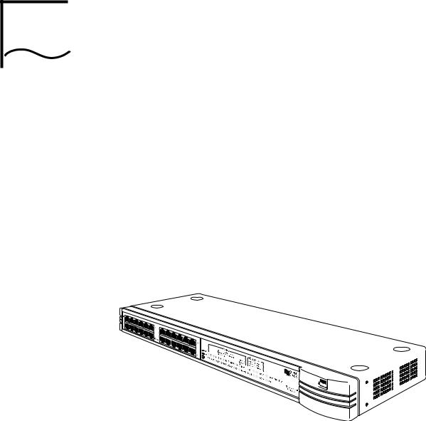
Introduction |
The SuperStack® II PS Hub, as shown in Figure 1-1, is a flexible |
|
managed Ethernet repeater which is very easy to set up and manage. |
|
It can be used to build a small network or to expand a larger, more |
|
established network. |
Figure 1-1 The PS Hub
The PS Hub is part of 3Com’s SuperStack II PS Hub range, which incorporates many of the features from the successful SuperStack II range. SuperStack II products can be combined to create a network that can change and grow with your networking needs.

1-2 CHAPTER 1: ABOUT THE PS HUB
Features The PS Hub 40 and PS Hub 50 share many features:
NOTE: These terms and features are described in this chapter and the following chapters.
■12 or 24 shielded twisted pair ports for easy connection to 10BASE-T networks. An MDI/MDIX switch allows you to cross-over one of these ports, for connection to other types of hubs and network equipment.
■One or two transceiver module slots, providing a choice of media options:
■The PS Hub 40 has two 10Mbps transceiver module slots that can be fitted with 3Com 10Mbps transceiver modules.
■The PS Hub 50 has one transceiver module slot that can be fitted with a 3Com 10Mbps or 100Mbps transceiver module.
■SuperStack II architecture — You can stack up to 10 hubs
(six if free standing), giving you a possible 260 ports per stack.
■LEDs for quick viewing of hub and port status.
■Hot-swappable technology which allows hubs to be added and removed from a stack without affecting stack performance.
■Mounting brackets for easy installation into a standard 19 inch rack, or onto a table or wall.
■+5 Lifetime Limited Warranty — Please refer to the “3Com Corporation Limited Warranty” at the back of this guide for more information.
DUA1640-5AAA02
|
Introduction 1-3 |
Management |
■ Complete SmartAgent™ management which is built into each hub; |
Features |
no additional management cards are needed. When PS Hubs are |
|
stacked, the management is distributed between all hubs in the |
|
stack. |
|
■ Easy to use built-in management interfaces for configuration of your |
|
hub or stack locally or over the network: |
|
■ A Command Line Interface for quick configuration of IP |
|
information for the hub. |
|
■ A web interface for comprehensive management of the hub |
|
using any suitable web browser. |
|
■ Additional management software (supplied on the CD-ROM), |
|
including 3Com’s Transcend® Quick Configuration Manager for |
|
Windows®. |
|
■ An implementation of SNMP for management over the network, |
|
using the IP protocol. |
|
■ Support for traps (messages) which can alert an SNMP network |
|
management station of any problems. |
|
■ Built-in security and resilience, which protects your network. |
|
■ Port switching — Allows you to build up workgroups by switching |
|
ports easily between the four internal segments. When stacked, all |
|
four segments are carried between the hubs by cascade cables. |
|
■ Automated load balancing — Configures the segments so that the |
|
traffic is distributed evenly across them, making the segments more |
|
efficient. It also analyses inter-segment traffic and moves frequently |
|
communicating ports to the same segment. |
DUA1640-5AAA02
1-4 CHAPTER 1: ABOUT THE PS HUB
How You Can |
The flexibility of the PS Hub allows it to be used in a number of ways. |
Use the PS Hub |
You can build up a network or expand a large, established network. |
|
For information on connecting and using your equipment, refer to |
|
Chapter 3. |
|
The PS Hub can be used on its own or in a stack with other PS Hubs. |
|
All PS Hubs have a useful feature called port switching which allows |
|
you to create workgroups within your stack. For information on this |
|
feature, refer to “Segments and Port Switching” on page 1-8. |
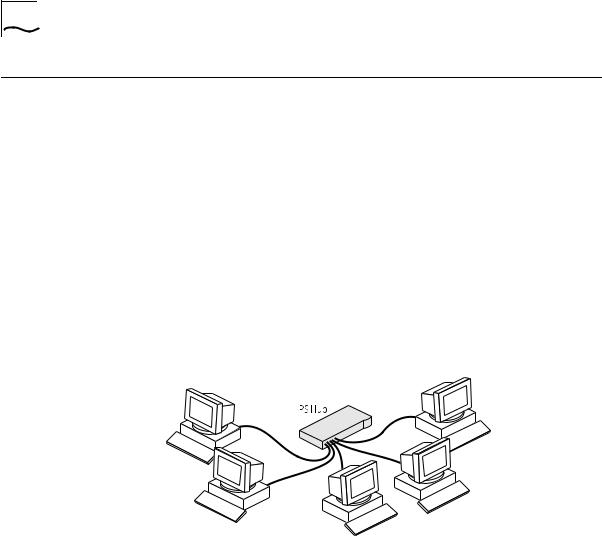
Building Up a |
The PS Hub is ideal for building up a new network. It has its own |
Network |
built-in management and comes ready to use. The PS Hub range is |
|
totally scalable, enabling you to start with one hub and add to it as |
|
your network grows. You can connect your workstations and other |
|
network equipment to the PS Hub to build a small network, as shown |
|
in Figure 1-2. |
Figure 1-2 Building Up a Network
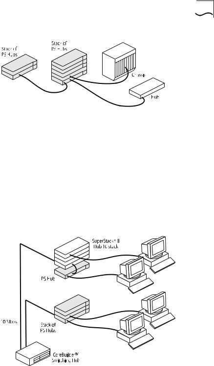
When your network grows, you can expand it easily by adding more PS Hubs. The PS Hub also has an MDI/MDIX switch which enables your network to expand further by connecting to other types of hubs, stacks and networking equipment, as shown in Figure 1-3.
DUA1640-5AAA02
How You Can Use the PS Hub 1-5
Figure 1-3 Connecting to Other Stacks and Hubs
Expanding an You can add PS Hubs to your existing network to expand the number Existing Network of user connections. Each PS Hub has its own built-in management
which is distributed throughout the PS Hubs in the stack. This provides fault tolerance because there is no single point of failure; all hubs have management capability (should they become isolated).
Figure 1-4 shows how PS Hubs can be added to an existing network (the network is a stack of SuperStack® II Hub 10 units in this example). The hubs create more ports now, and allow for further growth in the future. The PS Hubs are connected to a switch so that communication between them is controlled.
Figure 1-4 Expanding an Existing Network
DUA1640-5AAA02
1-6 CHAPTER 1: ABOUT THE PS HUB
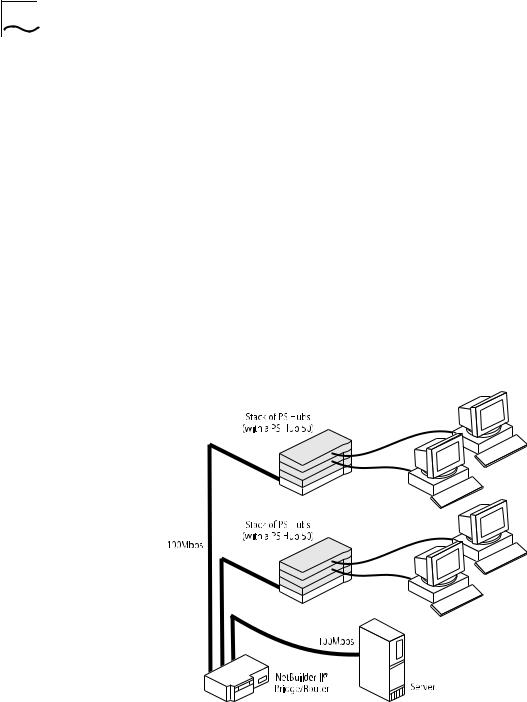
Migrating to Higher The PS Hub is ideal for migrating your existing network to a higher Performance performance network. Using its internal segments (each running at
10Mbps), you can build up separate workgroups within a PS Hub stack.
Having a PS Hub 50 in your PS Hub stack can extend the flexibility of your stack:
■The PS Hub 50 has an internal switch (called a segment switch) which can interconnect the segments in the stack so that the workgroups on the segments can communicate.
■The PS Hub 50 has a transceiver module slot which can be fitted with a 10Mbps or 100Mbps 3Com transceiver module, providing you with the option of having a 100Mbps network connection, for example 100BASE-TX or 100BASE-FX. This allows you to connect to 100Mbps networks or network equipment, for example a server.
For information on the differences between the PS Hub 40 and the
PS Hub 50, refer to Chapter 2.
Figure 1-5 Migrating to a Higher Performance Network
DUA1640-5AAA02
Workgroups 1-7
Workgroups |
An important feature of the PS Hub is that you can create workgroups. |
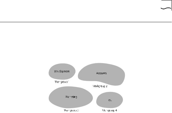
What Are A good way to organize your network is to neatly group your users in Workgroups? a logical way, called workgroups. For example, if your office consists of
four departments, you can mirror this by having four workgroups, as shown in Figure 1-6.
Figure 1-6 Workgroups
You can keep these workgroups separate from each other so that the communication is contained within each workgroup, or you can use the switching functionality of a PS Hub 50 to enable communication between the workgroups.
The workgroups are similar to the structure of your office, so it is easy for you to make changes to your network; adding and removing users, and moving users between workgroups.
The rest of this section describes how you can build up workgroups using your PS Hub.
DUA1640-5AAA02
1-8 CHAPTER 1: ABOUT THE PS HUB
Segments and The PS Hub has four separate internal repeaters (called segments) Port Switching which you can use to create your workgroups. You can switch the
hub’s ports to any of these segments (called port switching). With the segments and port switching, you can easily create your workgroups.
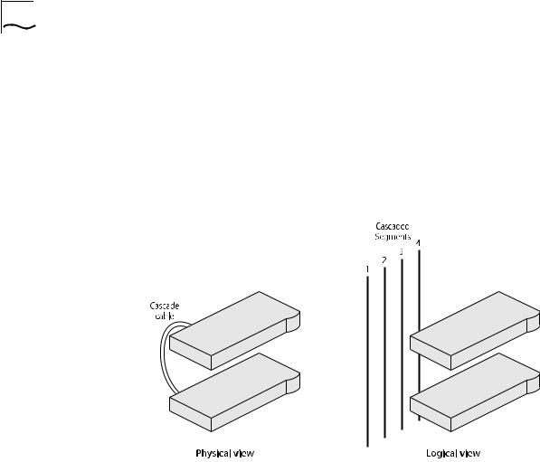
How the PS Hub Segments Work
In a stack of PS Hubs, four segments are carried between the hubs by the cascade cables. These segments are four separate networks internal to the stack, as shown in Figure 1-7.
Figure 1-7 Cascaded Segments
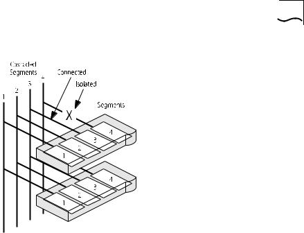
Each PS Hub has four internal segments. These segments are separate internal repeaters, and can connect to or remain isolated from their associated cascaded segments, as shown in Figure 1-8.
DUA1640-5AAA02
Workgroups 1-9
Figure 1-8 Internal Segments
You use management software to configure the segments. You can:
■Connect and isolate the segments from their associated cascaded segments.
■Switch the ports between the segments (port switching).
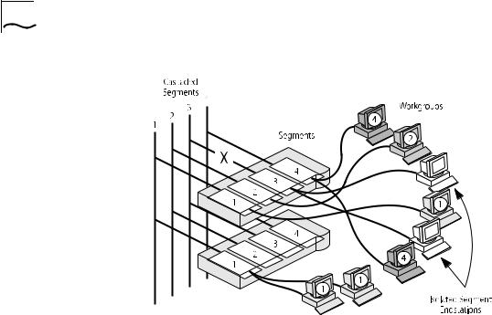
The ability to configure the segments allows you to create flexible workgroups, as shown in Figure 1-9, which can change and grow with your needs.
DUA1640-5AAA02
1-10 CHAPTER 1: ABOUT THE PS HUB
Figure 1-9 Workgroups
Benefits of Segments and Port Switching
The key to port switching is that you are not restricted by physical connections, and can create location and technology independent networks. This has many benefits:
■You can move users between segments easily — You simply switch the ports between the segments, as necessary, using management.
■The segments are carried throughout the stack — You can add hubs, when necessary, to extend the existing cascaded segments.
■Each segment is more efficient — Local network traffic is contained within each cascaded segment, so they avoid congestion from the other segments. You can increase the efficiency by using load balancing to configure the segments so that traffic is distributed evenly across them. You can use the web interface or Quick Config Manager to configure load balancing. For information on how load balancing works, refer to Chapter 4.
■Total bandwidth is higher — Each segment runs at 10Mbps, so four separate segments per hub provides a total of 40Mbps per hub.
■Configuration of the segments can be performed remotely — As users are moved between the segments by port switching, no physical changes have to be made.
DUA1640-5AAA02

Workgroups 1-11
■There is extra security — Hub segments can be isolated from the cascaded segments, so that only workstations on the same hub segment can communicate with each other.
■Port switching enables you to extend any existing workgroups you may have, across the whole network infrastructure, including shared Ethernet workgroups.
DUA1640-5AAA02

1-12 CHAPTER 1: ABOUT THE PS HUB
Workgroup Example This example shows how a stack of three PS Hubs can easily create a network with the desired workgroups. Table 1-1 shows how the users are grouped:
Table 1-1 |
Groupings |
|
|
|
|
Hub |
Development |
Accounts |
Marketing |
Test |
Isolated |
Top |
|
|
|
|
A, B, C |
Middle |
D, E, F, G |
H, I |
J |
K, L |
|
Bottom |
M, N, O |
|
P, Q |
|
R, S, T |
Figure 1-10 shows how the required workgroups are created using a stack of PS Hubs.
Figure 1-10 Workgroup Example (see Table 1-1)
DUA1640-5AAA02
 Loading...