


 Loading...
MSH SWITCH 1005
®USER GUIDE
Part No. DUA1840-0AAA01
Published June 1996
3Com Corporation ■ 5400 Bayfront Plaza ■ Santa Clara, California ■ 95052-8145
© 3Com Ireland, 1996. All rights reserved. No part of this documentation may be reproduced in any form or by any means or used to make any derivative work (such as translation, transformation, or adaptation) without permission from 3Com Ireland.
3Com Ireland reserves the right to revise this documentation and to make changes in content from time to time without obligation on the part of 3Com Ireland to provide notification of such revision or change.
3Com Ireland provides this documentation without warranty of any kind, either implied or expressed, including, but not limited to, the implied warranties of merchantability and fitness for a particular purpose. 3Com may make improvements or changes in the product(s) and/or the program(s) described in this documentation at any time.
UNITED STATES GOVERNMENT LEGENDS:
If you are a United States government agency, then this documentation and the software described herein are provided to you subject to the following restricted rights:
For units of the Department of Defense:
Restricted Rights Legend: Use, duplication or disclosure by the Government is subject to restrictions as set forth in subparagraph (c) (1) (ii) for restricted Rights in Technical Data and Computer Software clause at 48 C.F.R. 52.227-7013. 3Com Ireland, c/o Isolan House, Brindley Way, London Road, Hemel Hempstead, Herts., HP3 9XJ, United Kingdom.
For civilian agencies:
Restricted Rights Legend: Use, reproduction or disclosure is subject to restrictions set forth in subparagraph (a) through (d) of the Commercial Computer Software - Restricted Rights Clause at 48 C.F.R. 52.227-19 and the limitations set forth in 3Com Corporation’s standard commercial agreement for the software. Unpublished rights reserved under the copyright laws of the United States.
If there is any software on removable media described in this documentation, it is furnished under a license agreement included with the product as a separate document, in the hard copy documentation, or on the removable media in a directory file named LICENSE.TXT. If you are unable to locate a copy, please contact 3Com and a copy will be provided to you.
Unless otherwise indicated, 3Com registered trademarks are registered in the United States and may or may not be registered in other countries.
3Com, LinkBuilder and Transcend are registered trademarks of 3Com Corporation. SuperStack II, PACE, VLT, Virtual LAN Trunk and 3TECH are trademarks of 3Com Corporation. 3ComFacts is a service mark of 3Com Corporation.
CompuServe is a registered trademark of CompuServe, Inc..
Other brand and product names may be registered trademarks or trademarks of their respective holders.

CONTENTS
ABOUT THIS GUIDE
|
Introduction |
1 |
|
|
|
|
|
|
|
How to Use This Guide |
1 |
|
|
|
|
||
|
Conventions |
2 |
|
|
|
|
|
|
|
Related Publications |
3 |
|
|
|
|
||
|
|
|
|
|
|
|||
1 GETTING STARTED |
|
|
|
|
||||
|
About the LinkBuilder MSH |
1-1 |
|
|||||
|
About the MSH Switch 1005 |
|
1-1 |
|
||||
|
Summary of Features |
1-2 |
|
|
||||
|
Port Connections |
1-3 |
|
|
|
|
||
|
10BASE-T Switch Ports |
1-3 |
|
|||||
|
Internal Switch Ports |
|
1-3 |
|
||||
|
Transceiver Module Ports |
1-4 |
||||||
|
The Backbone Port |
1-4 |
|
|
||||
|
Adding an Expansion Module |
1-4 |
||||||
|
Switch Operation and Features |
1-5 |
||||||
|
How the Switch Compares to a Bridge 1-5 |
|||||||
|
Forwarding of Packets |
|
1-5 |
|
||||
|
Intelligent Flow Management |
1-7 |
||||||
|
Full Duplex |
1-8 |
|
|
|
|
|
|
|
Security 1-8 |
|
|
|
|
|
|
|
|
Resilient Links |
1-8 |
|
|
|
|
|
|
|
Virtual LANs (VLANs) |
1-8 |
|
|
||||
|
PACE 1-9 |
|
|
|
|
|
|
|
|
MSH Switch 1005 on Your Network |
1-11 |
||||||
|
Server Connections |
1-11 |
|
|
||||
|
Network Configuration Examples |
1-11 |
||||||
|
Configuration Rules for Fast Ethernet |
1-15 |
||||||
|
Configuration Rules with Full Duplex |
1-15 |
||||||
|
Switch Overview — Front Panel |
1-16 |
|
|
||||
|
LEDs 1-17 |
|
|
|
|
|
|
|
|
Transceiver Module slot |
1-18 |
|
|
||||
|
10BASE-T Ports |
1-18 |
|
|
|
|
|
|
|
Switch Overview — PCB View |
1-19 |
|
|
||||
|
Transceiver Module Connector [1] |
1-19 |
||||||
|
Expansion Module Fixing Posts [2] |
1-20 |
||||||
|
Links LK 1 to LK 5 [3] 1-20 |
|
|
|
|
|||
|
Expansion Module Socket [4] |
1-20 |
|
|||||
|
Backplane Connectors [5] |
|
1-20 |
|
|
|||
|
Switch Defaults |
1-20 |
|
|
|
|
|
|
|
Setting Up the MSH Switch 1005 for Management 1-21 |
|||||||
|
|
|||||||
2 INSTALLATION AND INITIAL SETUP |
||||||||
|
Safety Information |
2-1 |
|
|
|
|
|
|
|
Pre-installation Configuration |
|
2-2 |
|
|
|||
|
Setting the Links on the Switch 1005 |
2-2 |
||||||
|
Advice for Setting Backplane Connections and Avoiding Loops 2-4 |
|||||||
|
Fitting a Transceiver Module |
2-5 |
|
|
||||
|
Fitting an Expansion Module |
2-5 |
|
|
||||
|
Switch 1005 Installation and Removal |
2-6 |
||||||
|
Installing the Switch 1005 |
|
2-6 |
|
|
|||
|
Removing the Switch 1005 |
|
2-7 |
|
|
|||
|
Operation after Power-up |
|
2-7 |
|
|
|||
|
In an Unmanaged System |
|
2-7 |
|
|
|||
|
In a Managed System |
2-8 |
|
|
|
|||
|
Setting up the Switch 1005 |
2-9 |
|
|
|
|||
|
Using the VT100 Interface |
|
2-9 |
|
|
|||
|
Using Telnet |
2-12 |
|
|
|
|
|
|
|
Using an SNMP Network Manager |
2-12 |
||||||
|
Accessing the Switch 1005 VT100 Interface |
2-13 |
||||||

Logging On |
2-14 |
|
After Logging On |
2-15 |
|
Switch 1005 Management Setup 2-17 |
||
Logging Off |
2-19 |
|
Auto Logout |
2-19 |
|
Setting Up Users |
2-20 |
|
Creating a New User |
2-21 |
|
Deleting a User 2-22 |
||
Editing User Details |
2-23 |
|
Assigning Local Security 2-24
3 SWITCH CONFIGURATION
Choosing a Switch Management Level |
3-1 |
|||||
Switch 1005 Setup |
3-4 |
|
|
|
||
Port Setup 3-7 |
|
|
|
|
|
|
Specifying the Backbone Port |
3-11 |
|||||
The Switch Database (SDB) |
3-12 |
|
|
|||
Configuring the Switch Database |
3-14 |
|||||
Searching the Switch Database |
3-15 |
|||||
By MAC Address |
3-15 |
|
|
|||
By Port |
3-15 |
|
|
|
|
|
Adding an Entry into the SDB |
3-16 |
|||||
Deleting an Entry from the SDB |
3-16 |
|||||
Resilient Links |
3-17 |
|
|
|
|
|
Viewing Resilient Setup |
3-18 |
|
|
|||
Configuring Resilient Links 3-20 |
|
|||||
Creating a Resilient Link |
3-22 |
|
|
|||
Deleting a Resilient Link |
3-22 |
|
|
|||
Setting Up Traps |
3-23 |
|
|
|
||
Resetting the Switch 1005 |
3-25 |
|
|
|||
Initializing the Switch 1005 |
3-26 |
|
|
|||
Upgrading Software |
3-28 |
|
|
|
||

4 ADVANCED MANAGEMENT
Virtual LANs (VLANs) |
4-1 |
|
|
What are VLANs? 4-1 |
|
||
Benefits of VLANs |
4-2 |
|
|
An Example |
4-3 |
|
|
VLANs and the Switch 1005 4-4 |
|
||
The Default VLAN |
4-4 |
|
|
Connecting VLANs to a Router |
4-4 |
||
Connecting Common VLANs Between Switches 4-5 |
|||
Using Non-routable Protocols |
4-5 |
||
Using Unique MAC Addresses |
4-5 |
||
VLAN Configurations 4-6 |
|
||
Example 1 |
4-6 |
|
|
Example 2 |
4-8 |
|
|
Example 3 |
4-10 |
|
|
Setting Up VLANs on the Switch 4-12
|
Assigning a Port to a VLAN |
4-15 |
|||
|
Specifying a Backbone Port |
4-15 |
|||
|
Specifying that a Backbone Port is Part of a VLT 4-15 |
||||
|
|
||||
5 STATUS MONITORING AND STATISTICS |
|||||
|
Summary Statistics |
5-2 |
|
||
|
Port Statistics |
5-4 |
|
|
|
|
Port Traffic Statistics |
5-6 |
|
||
|
Port Error Analysis |
5-9 |
|
||
|
Status Monitoring |
5-11 |
|
||
|
Remote Polling |
5-13 |
|
||
|
|
|
|||
6 PROBLEM SOLVING |
|
||||
|
Spot Checks |
6-1 |
|
|
|
|
Identifying Fault Conditions with the LEDs 6-2 |
||||
|
VT100 Problems |
6-3 |
|
||
|
Switch 1005 Operation Problems |
6-4 |
|||

ASCREEN ACCESS RIGHTS
BTECHNICAL SPECIFICATION
CTECHNICAL SUPPORT
Online Technical Services |
C-1 |
|
|
|
3Com Bulletin Board Service |
C-1 |
|
||
Access by Modem |
C-1 |
|
|
|
Access by ISDN |
C-2 |
|
|
|
World Wide Web Site |
C-2 |
|
|
|
3ComForum on CompuServe |
C-3 |
|
||
3ComFacts Automated Fax Service |
C-3 |
|||
Support from Your Network Supplier |
C-4 |
|||
Support from 3Com |
C-5 |
|
|
|
Returning Products for Repair C-6
GLOSSARY
INDEX
LIMITED WARRANTY
ABOUT THIS GUIDE
Introduction
This guide describes how to install and configure the MSH Switch 1005.
If the information in the release notes shipped with your product differs from the information in this guide, follow the release notes.
How to Use This Guide
The following table shows where to find specific information in this guide.
If you are looking for: |
Turn to: |
|
|
A description of all the Switch 1005 features and a guide to making a |
Chapter 1 |
quick start with management |
|
Important safety information, a brief overview of the installation process |
Chapter 2 |
and a complete guide the initial setup required |
|
Information and steps telling you how you can manage the Switch 1005 |
Chapter 3 |
using the VT100 screens |
|
Information on the more advanced functionality you can manage using |
Chapter 4 |
the VT100 screens |
|
Details on viewing Switch 1005 statistics using the VT100 screens |
Chapter 5 |
Ideas on solving problems should they arise |
Chapter 6 |
A list of user access rights for the VT100 screens |
Appendix A |
Technical information about the Switch 1005 |
Appendix B |
Technical support information |
Appendix C |
A list of terms and definitions used in this Guide |
Glossary |
A comprehensive Index |
Index |
|
|

2 ABOUT THIS GUIDE
Conventions
Table 1 and Table 2 list text and icon conventions that are used throughout this guide:
Table 1 |
Notice Icons |
|
|
Icon |
Type |
|
Description |
|
Information Note |
Information notes call attention to |
|
|
|
|
important features or instructions. |
|
Caution |
|
Cautions alert you to personal safety risk, |
|
|
|
system damage, or loss of data. |
|
Warning |
|
Warnings alert you to the risk of severe |
|
|
|
personal injury. |
Table 2 |
Text Conventions |
|
|
Convention |
Description |
||
“Enter” vs. “Type” |
When the word “enter” is used in this guide, it means type |
||
|
|
something, then press the Return or Enter key. Do not press |
|
|
|
the Return or Enter key when an instruction simply says “type.” |
|
Text represented as |
This |
typeface is used to represent displays that |
|
screen |
appear on your terminal screen, for example: |
||
display |
NetLogin: |
||
|
|
||
Text represented as |
This |
typeface is used to represent commands that |
|
commands |
you enter, for example: |
||
|
|
SETDefault !0 -IP NETaddr = 0.0.0.0 |
|
Keys |
|
When specific keys are referred to in the text, they are called |
|
|
|
out by their labels, such as “the Return key” or “the Escape |
|
|
|
key,” or they may be shown as [Return] or [Esc]. |
|
|
|
If two or more keys are to be pressed simultaneously, the keys |
|
|
|
are linked with a plus sign (+), for example: |
|
|
|
Press [Ctrl]+[Alt]+[Del]. |
|
Italics |
|
Italics are used to denote new terms or emphasis. |
|
Related Publications |
3 |
Related Publications
This User Guide is not intended to answer all your questions concerning the MSH. While using the MSH Switch 1005, you may need to refer to the following publications:
■LinkBuilder MSH User Guide, part number DUA1800-0AAA0x.
■LinkBuilder MSH Management Module User Guide, part number DUA1850-0AAA0x.

4 ABOUT THIS GUIDE

1 GETTING STARTED
About the LinkBuilder MSH
The LinkBuilder MSH is an extremely versatile, chassis-based hub that allows you to connect and manage large, mixed-technology, mixed-media LANs.
The basis of the MSH is the chassis into which you can install a series of network-specific modules. Modules within the chassis connect to a number of backplanes allowing communication between the various LANs and LAN segments connected to the MSH.
About the MSH Switch 1005
The MSH Switch 1005 is designed to be installed into the MSH chassis, so that you can extend your network beyond the limits of a repeater and provide your users with greater bandwidth, faster throughput, and high speed connections.
The MSH Switch 1005 is an intelligent module with its own on-board management agent. This means that even in an unmanaged MSH chassis, you can access the manageable features of the Switch using a Telnet application or an SNMP Network Manager and configure internal port connections using the five links located on the Switch.
With a Management Module installed into your MSH chassis, you have access to the VT100 interface of the Switch. This interface provides a series of ASCII character-based forms which allow you to configure the manageable features of the Switch. You can find further information about Switch management in “Setting up the Switch 1005” in
Chapter 2.

1-2 CHAPTER 1: GETTING STARTED
Summary of Features
■8 switched 10BASE-T ports
■Slot for optional Fast Ethernet or 10BASE-T Transceiver Module
■Switched connections to all 3 internal Ethernet backplanes
■Internal Fast Ethernet backplane
■Ability to add Expansion Module adding up to three further Transceiver Modules
■Support for up to 500 end-stations, unlimited stations on backbone port
■Forwarding modes for packets
■Low latency in fast forward mode
■No runts in fragment free mode
■No runts/errors in store-and-forward mode
■Low latency or no runts/errors in intelligent mode
■Intelligent Flow Management when packet buffers are full
■Prevents packets being discarded
■Suppresses transmissions at source
■Full duplex on Fast Ethernet Transceiver Modules
■Security
■Resilient Links
■Port-based Virtual LANs (VLANs)
■Support for up to 16 VLANs on a single Switch 1005
■Eases the movement of devices on IP networks
■Controls traffic
■Provides extra security
■PACE (Priority Access Control Enabled)
■Supports multimedia applications over Ethernet
■Increased Ethernet predictability
■Full use of network bandwidth
DUA1840-0AAA01

About the MSH Switch 1005 |
1-3 |
■SmartAgent support
■SNMP with IP and IPX protocols
■RMON
■Repeater and Bridge MIB
■Broadcast storm control
■Easy software upgrades
■BOOTP
■Local management
Port Connections
10BASE-T Switch Ports
Eight fixed ports each configured as MDIX provide 10Mbps bandwidth to each attached end-station. Maximum segment length is 100m (328ft) over grade 3, 4 or 5 twisted pair cable.
Internal Switch Ports
As well as switch ports located on the front panel of the Switch 1005, internal backplane connections provide an additional four switch ports. These ports are enabled and disabled through management or using the set of links LK1 to LK5 located on the Switch 1005.
Three of these ports provide switched connections to the three 10Mbps repeater backplanes located in the MSH chassis, and therefore to any modules connected to the same backplane.
The fourth internal switched port provides a connection to the Fast Ethernet backplane, and therefore to any other Switch 1005 modules installed in the chassis.
Locating and setting links is described in “Setting the Links on the Switch 1005” in Chapter 2.
DUA1840-0AAA01

1-4 CHAPTER 1: GETTING STARTED
Transceiver Module Ports
A slot on the front of the Switch 1005 allows you to install any of the Transceiver Modules available for this product. You can find more details in “Transceiver Module slot” on page 1-18.
The Backbone Port
The MSH Switch 1005 requires that the port connecting it to the rest of your network is configured as a backbone port. This is the port to which all frames arriving at a switch port with an unknown destination address will be forwarded. Addresses received on the backbone port are not stored in the switch database of the Switch 1005.
When you first install a Switch 1005 into your MSH chassis, it will configure its backbone port to be the first Fast Ethernet port it finds either on the Switch, or on the Expansion Module if fitted. You can change your designated backbone port to be any switch port (internal or external). Changing the default backbone port is described in “Specifying the Backbone Port” in Chapter 3.
You can only have one backbone port per Switch 1005, unless you have implemented multiple VLANs on one Switch; in this case you can configure one backbone port per VLAN. You can find more information about VLANs in Chapter 4.
Adding an Expansion Module
The MSH Switch 1005 also has provision for installing an Expansion Module. The Expansion Module has three slots for installing any combination of the Transceiver Modules described in “Transceiver Module slot” on page 1-18.
DUA1840-0AAA01

Switch Operation and Features |
1-5 |
Switch Operation and Features
How the Switch Compares to a Bridge
The table below shows how Switch 1005 operation compares to that of an IEEE 802.1D bridge:
|
IEEE 802.1D Bridge |
Switch 1005 |
Address Learning |
All ports |
All ports except backbone. |
Forwarding Mode |
Store-and-forward |
Fast Forward, Fragment |
|
|
Free, Store and Forward, or |
|
|
Intelligent |
Operation when packet |
Discard packets |
Invoke Intelligent Flow |
buffers full |
|
Management to suppress |
|
|
transmissions at source |
Spanning Tree |
Supported |
Not supported |
Action on Unknown |
Flood all ports |
Forward to backbone port |
Destination Address |
|
only |
Database size |
Variable |
500 addresses |
In all other ways, MSH Switch 1005 and bridge operation is identical.
Forwarding of Packets
The table below shows how a packet is processed when it arrives at the Switch 1005:
Packet Source |
Destination Address |
Action |
Any port EXCEPT backbone port |
Unknown |
Forward to backbone |
(Unicast packet) |
|
port only |
Any port EXCEPT backbone port |
Same port as source |
Filter (discard) |
(Unicast packet) |
address |
|
Any port EXCEPT backbone port |
Another port (not |
Forward to specific port |
(Unicast packet) |
backbone port) |
only |
DUA1840-0AAA01

1-6 |
CHAPTER 1: GETTING STARTED |
|
|
|
Packet Source |
Destination Address |
Action |
|
Any port EXCEPT backbone port |
Not applicable |
Forward to all ports |
|
(Multi/Broadcast packet) |
|
(including backbone |
|
|
|
port) within same VLAN |
|
|
|
as source port |
|
Backbone port (Unicast packet) |
Unknown |
Filter (discard) |
|
Backbone port (Unicast packet) |
Known on a port (not |
Forward to specific port |
|
|
backbone port) |
only |
|
Backbone port |
Not applicable |
Forward to all ports |
|
(Multi/Broadcast packet) |
|
within specific VLAN |
To best suit your networking requirements, the Switch 1005 allows you to set one of four frame forwarding modes:
■Fast Forward — In this mode, frames are forwarded as soon as the destination address is received and verified. The forwarding delay, or latency, for all frames in this mode is just 40µs but with the lack of checking time, any collision fragments or error frames received are propagated through the switch.
■Fragment Free — In this mode, a minimum of 64 bytes of the received frame is buffered prior to the frame being forwarded. This ensures that collision fragments are not propagated through the network, however, CRC errors are forwarded. The forwarding delay, or latency, for all frames in this mode is 64µs.
■Store and Forward — In this mode, received packets are buffered in their entirety prior to forwarding. This ensures that only good frames are passed to their destination. The forwarding delay for this mode varies between 64µs and 1.2ms, depending on frame length. In Store and Forward mode, latency is measured as the time between receiving the last bit of the frame, and transmitting the first bit. For the Switch 1005, this is 8µs.
■Intelligent — In this mode, the Switch 1005 monitors the amount of error traffic on the network and changes the forwarding mode accordingly. If the Switch 1005 detects less than 18 packets per second with errors, it will operate in Fast Forward mode. As soon as the Switch 1005 detects more than 18 packets per second with errors, it will operate in Store and Forward mode until the error count returns to 0.
DUA1840-0AAA01

Switch Operation and Features |
1-7 |
Intelligent Flow Management
Intelligent Flow Management (IFM) is a congestion control mechanism built into the Switch 1005. Congestion is caused by one or more devices sending traffic to a Switch port which is already busy. The Switch 1005 contains both input and output packet buffers and while congestion is rare, IFM is designed to alleviate problems during those moments when packet buffers in the Switch 1005 are full. IFM will prevent packet loss by inhibiting the transmitting device from sending any further packets until the port is no longer congested.
If a packet arrives at a conventional switch that does not operate IFM, and that port is congested, the transmitting device is unaware of this until it times out and decides that the receiving station is not going to respond to the message. This can take as long as 30 seconds, and depending on the protocol you are running, may not happen until many packets have been sent. The transmitting device then has to retransmit the packets, effectively wasting bandwidth.
Switch modules implementing IFM are aware of congestion, and prevent packet loss by inhibiting the transmitting device from transmitting the packet in the first place. It does this by forcing the device to retransmit the packet later. This “back-off” and retransmission happens very quickly (typically less than one second) and is much faster than waiting for the transmitting device to time-out. There are two benefits:
■the packet is transmitted quickly and successfully
■the packet is only transmitted once, thereby saving bandwidth.
IFM is designed to be enabled on ports connected to a single network device. If IFM is enabled on a port connected to multiple devices through a repeater, packet congestion within the Switch 1005 could result in packet transmission between two devices connected to the repeater being inhibited.
DUA1840-0AAA01

1-8 CHAPTER 1: GETTING STARTED
Full Duplex
The MSH Switch 1005 provides full duplex support for any Fast Ethernet Transceiver Modules you may have installed. Full duplex allows frames to be transmitted and received simultaneously and, in effect, doubles the bandwidth available on the link. Full duplex also supports 100BASE-FX cable runs of up to 2km.
Security
The MSH Switch 1005 contains advanced security features which guard against users connecting unauthorized stations onto your network. When security is enabled on a port, that port enters into a single address learning mode. This port is then permitted to learn just a single Ethernet address and once this is learned, if a different address is then seen on that port, the port will be disabled. Until security is disabled, no other address can be learned.
Resilient Links
The Resilient Link feature in the Switch 1005 enables you to protect critical links and prevent wasteful network downtime should that link fail. Setting up resilience ensures that should a main communication link fail, a standby duplicate link will immediately and automatically take over the task of the main link. Each main and standby link pair is referred to as a resilient link pair. The main and standby links must be set up on the same Switch 1005.
Virtual LANs (VLANs)
The Switch 1005 has a Virtual LAN (VLAN) feature which allows you to build your network segments without being restricted by physical connections. A VLAN is defined as a group of locationand topology-independent devices that communicate as if they are on the same physical LAN.
DUA1840-0AAA01
Switch Operation and Features |
1-9 |
Implementing VLANs on your network has three main advantages:
■Network administration personnel are required to make less physical intervention when a workstation has to be moved. Within the VLAN setup, a group of devices on different floors in a building can be configured into a common communications group. If a workstation is moved from VLAN 1 to VLAN 2 for example, the network administrator only needs to know address information for that device; the physical location of the port is irrelevant.
■Use of network resources becomes much more efficient. Each VLAN can be set up to contain only those devices which need to communicate with each other. In this way, broadcast storms, the most common cause of network congestion, can also be avoided.
■Network security is enhanced. Devices within each VLAN can only communicate with member devices in the same VLAN. If a device in VLAN 1 for example, needs to communicate with devices in VLAN 2, it must be configured to cross the router between them.
Further information can be found in Chapter 4.
PACE
PACE (Priority Access Control Enabled) technology allows multimedia applications using voice and video traffic to be carried over standard Ethernet and Fast Ethernet Local Area Networks (LANs). PACE provides the quality of service that these applications require, reducing latency to a minimum and prioritizing the multimedia traffic.
Both multimedia and data traffic are improved considerably by introducing an Ethernet switch into the LAN and attaching each end-station to its own dedicated 10Mbps switch port. This removes any contention between different end-stations for the Ethernet bandwidth. However, when two-way traffic is passing between an end-station and the switch port, access to the bandwidth can still be unfairly allocated to traffic in one direction, resulting in poor quality video display. PACE allocates the available bandwidth fairly to traffic in each direction. In this way, existing Ethernet adapters and cabling can be used to run high-quality multimedia sessions across the LAN.
DUA1840-0AAA01

1-10 CHAPTER 1: GETTING STARTED
You can enable PACE on the whole Switch 1005 module or on an individual port. Before configuring PACE, you should refer to sections “Switch 1005 Setup” and “Port Setup” in Chapter 3.
DUA1840-0AAA01

MSH Switch 1005 on Your Network |
1-11 |
MSH Switch 1005 on Your Network
Server Connections
When integrating the Switch 1005 into your network, the following notes on server connections will ensure that it is operating at maximum efficiency:
■Ideally ...
... any local server should be connected to the Switch 1005 using a 100Mbps port.
■If that is not possible ...
... connect the local server to a dedicated 10Mbps port.
■If that’s not possible and the local server is connected to a repeated segment where the traffic is mainly local to that segment ...
... disable Intelligent Flow Management (IFM) on the port to which the repeater is connected.
Whenever you have multiple workstations connected to a single port of the Switch 1005, we recommend that you disable IFM on that port.
Network Configuration Examples
The following illustrations show some examples of how the Switch 1005 can be used on your network.
DUA1840-0AAA01

1-12 |
CHAPTER 1: GETTING STARTED |
|
Figure 1-1 Workgroup Switch I |
Figure 1-1 shows how the Switch 1005 fits into a large corporate network with a Fast Ethernet infrastructure. A Switch is positioned on each floor and servers are centralized in the basement.
DUA1840-0AAA01
|
|
|
|
|
|
|
|
|
|
|
|
|
|
MSH Switch 1005 on Your Network |
1-13 |
|
|
|
|
|
|
|
|
|
|
|
|
|
|
|
|
|
|
|
|
|
|
|
|
|
|
|
|
|
|
|
|
|
|
|
|
|
|
|
|
|
|
|
|
|
|
|
|
|
|
|
|
|
|
|
|
|
|
|
|
|
|
|
|
|
|
|
|
|
|
|
|
|
|
|
|
|
|
|
|
|
|
|
|
|
|
|
|
|
|
|
|
|
|
|
|
|
|
|
|
|
|
|
|
|
|
|
|
|
|
|
|
|
|
|
|
|
|
|
|
|
|
|
|
|
|
|
|
|
|
|
|
|
|
|
|
|
|
|
|
|
|
|
|
|
|
|
|
|
|
|
|
|
|
|
|
|
|
|
|
|
|
|
|
|
|
|
|
|
|
|
|
|
|
|
|
|
|
|
|
|
|
|
|
|
|
|
|
|
|
|
|
|
|
|
|
|
|
|
|
|
|
|
|
|
|
|
|
|
|
|
|
|
|
|
|
|
|
|
|
|
|
|
|
|
|
|
|
|
|
|
|
|
|
|
|
|
|
|
|
|
|
|
|
|
|
|
|
|
|
|
|
|
|
|
|
Figure 1-2 Workgroup Switch II
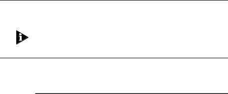
Figure 1-2 shows the Switch 1005 in a second workgroup situation. This setup could be that of a small office within a large corporation, or part of a larger corporate network. Each switch port has mainly muliple end-stations.
DUA1840-0AAA01
1-14 |
CHAPTER 1: GETTING STARTED |
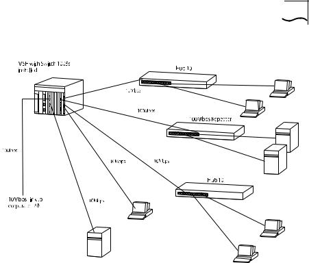
Figure 1-3 Desktop Switch
Figure 1-3 shows the Switch 1005 used for a group of heavy-traffic users in a large corporate network. Here, switching is brought to the desktop with a single end-station per switch port. Local servers are connected via a 100Mbps Fast Ethernet link.
DUA1840-0AAA01

Configuration Rules for Fast Ethernet |
1-15 |
Configuration Rules for Fast Ethernet
The topology rules for Fast Ethernet (100Mbps) are slightly different to those for 10Mbps Ethernet. The key topology rules are:
■Maximum UTP cable length is 100m (328ft) over category 5 cable.
■A 412m (1352ft) fiber run is allowed for connecting switch to switch, or end-station to switch, using standards-compliant half-duplex 100BASE-FX.
■A total network span of 325m (1066ft) is allowed in single-repeater topologies (one hub stack per wiring closet with a fiber run to the collapsed backbone); for example, a 225m (738ft) fiber downlink from a repeater to a router or switch, plus 100m (328ft) UTP run from a repeater out to the desktops.
Configuration Rules with Full Duplex
The MSH Switch 1005 provides full duplex support for any Fast Ethernet Transceiver Modules that are installed. Full duplex allows frames to be transmitted and received simultaneously and, in effect, doubles the bandwidth available on a link.
With full duplex, the topology rules are:
■Maximum UTP cable length is still 100m (328ft) over category 5 cable.
■A 2km (6562ft) fiber run is allowed for connecting switch to switch, or end-station to switch.
DUA1840-0AAA01
1-16 CHAPTER 1: GETTING STARTED
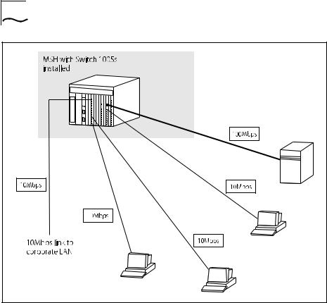
Switch Overview — Front Panel
Figure 1-4 Switch 1005 front view
DUA1840-0AAA01

Switch Overview — Front Panel |
1-17 |
LEDs
LED |
Color |
Indicates ... |
|
PWR |
Green |
The Switch is powered up and operating |
|
(Power) |
|
normally. |
|
|
Green flash |
Power On Self Test (POST) in operation. |
|
|
(slow, 0.5 Hz) |
|
|
|
Green flash |
Software download in progress |
|
|
(fast, 1Hz) |
|
|
|
Amber |
Fault occurred on this Switch |
|
Backplane |
|
|
|
E |
Green |
One or more of the internal Ethernet (10Mbps) |
|
|
|
backplanes are enabled. |
|
|
Green flash |
All three internal Ethernet backplanes are |
|
|
|
disabled. |
|
|
Yellow |
There is network activity on the enabled |
|
|
|
backplane(s). |
|
FE |
Green |
Connection to the internal Fast Ethernet |
|
|
|
(100Mbps) backplane is enabled. |
|
|
Green flash |
Connection to the internal Fast Ethernet |
|
|
|
(100Mbps) backplane is disabled. |
|
|
Yellow |
There is network activity on the Fast Ethernet |
|
|
|
backplane. |
|
1 - 12 |
Green |
Link connected; port enabled. |
|
(External port |
Green flash |
Link connected; port disabled. |
|
status) |
|||
Yellow |
Traffic being transmitted/received on this port. |
||
|
|||
|
Off |
Link not connected. |
Ports 1 - 4 relate to any Transceiver Module installed into the slot. If you have installed a Fast Ethernet Transceiver Module, LED 1 will be lit, all others are unused.
For information on using the LEDs for fault diagnosis, please see “Identifying Fault Conditions with the LEDs” in Chapter 6.
DUA1840-0AAA01

1-18 CHAPTER 1: GETTING STARTED
Transceiver Module slot
Allows you to install an Transceiver Module. Transceivers available include:
■100BASE-TX Transceiver Module (3C18407) — This Fast Ethernet, 100Mbps, twisted pair port provides the Switch with a single, high-speed connection to, for example, your network infrastructure. Maximum segment length is 100m (328ft) over grade 5 twisted pair cable.
■100BASE-FX Transceiver Module (3C18408) — This Fast Ethernet, 100Mbps, fiber port provides the Switch with a single, high-speed connection to, for example, your network infrastructure. Use 62.5/125 micron fiber optic cable with SC connectors. The maximum supported distance is 412m (1352ft) or 2km (6562ft) if the devices at both ends of the link support full duplex.
■4 Port 10BASE-T Transceiver Module (3C18409) — Adds an additional four 10BASE-T ports to your Switch 1005 with the same operating conditions as the eight fixed ports described below.
You should contact your supplier for further details on these and any further Transceiver Modules available from 3Com.
10BASE-T Ports
Eight fixed ports each configured as MDIX provide the full 10Mbps bandwidth to each attached end-station. Maximum segment length is 100m (328ft) over grade 3, 4 or 5 twisted pair cable.
DUA1840-0AAA01
Loading...