


LINKBUILDER MSH 4 PORT ETHERNET BRIDGE MODULE
Table of contents
 Loading...
T
HE
L
INK
B
UILDER
MSH
4 P
ORT
E
THERNET
B
RIDGE
M
ODULE
U
SER
G
UIDE
Part No. DUA1860-0AAA01
Published November 1994

3Com Corporation ■
5400 Bayfront Plaza ■ Santa Clara, California ■
95052-8154
© 3Com Corporation, 1994. All rights reserved. No part of this documentation may be reproduced in
any form or by any means or used to make any derivative work (such as translation, transformation, or
adaptation) without permission from 3Com Corporation.
3Com Corporation reserves the right to revise this documentation and to make changes in content
from time to time without obligation on the part of 3Com Corporation to provide notification of such
revision or change.
3Com Corporation provides this documentation without warranty of any kind, either implied or
expressed, including, but not limited to, the implied warranties of merchantability and fitness for a
particular purpose. 3Com may make improvements or changes in the product(s) and/or the program(s)
described in this documentation at any time.
UNITED STATES GOVERNMENT LEGENDS:
If you are a United States government agency, then this documentation and the software described
herein are provided to you subject to the following restricted rights:
For units of the Department of Defense:
Restricted Rights Legend: Use, duplication or disclosure by the Government is subject to restrictions as
set forth in subparagraph (c) (1) (ii) for restricted Rights in Technical Data and Computer Software
clause at 48 C.F.R. 52.227-7013. 3Com Corporation, 5400 Bayfront Plaza, Santa Clara, California
95052-8145.
For civilian agencies:
Restricted Rights Legend:
Use, reproduction or disclosure is subject to restrictions set forth in
subparagraph (a) through (d) of the Commercial Computer Software - Restricted Rights Clause at 48
C.F.R. 52.227-19 and the limitations set forth in 3Com’s standard commercial agreement for the
software. Unpublished rights reserved under the copyright laws of the United States.
3Com and LinkBuilder are registered trademarks of 3Com Corporation. Registered trademarks are
registered in the United States, and may or may not be registered in other countries.
3ComFacts, Ask3Com, CardFacts, NetFacts, and CardBoard are service marks of 3Com
Corporation.
CompuServe is a registered trademark of CompuServe, Inc.
The technology behind 3Com’s LAN Security Architecture is protected by U.S. patent 5161192 (world
patents pending).
Other brand and product names may be registered trademarks or trademarks of their respective
holders.
Revision: 01

C
ONTENTS
A
BOUT
T
HIS
G
UIDE
Introduction ix
How To Use This Guide x
Conventions xi
Special Messages xii
Related Publications xiii
1
I
NTRODUCTION
The LinkBuilder MSH 1-2
The LinkBuilder MSH 4 Port Ethernet Bridge Module 1-3
Managing The Bridge 1-7
Bridging 1-8
Why Use A Bridge? 1-8
Local And Remote Bridges 1-9
Bridge Network Topology 1-10
Learning, Filtering And Forwarding 1-12
Spanning Tree Algorithm And Protocol (STAP) 1-16
Bridge Filters 1-20
What Is Custom Filtering? 1-20
Filter Sets 1-23
Host-to-Host Filtering 1-23
Host-to-Port Filtering 1-24
Port-to-Port Filtering 1-26
Multicast-to-Port Filtering 1-27
Protocol Filtering 1-27
Bit Filtering 1-28
Enabling Custom Filtering 1-29
Simple Network Management Protocol (SNMP) 1-30
Installation And Removal 1-31
Safety Information 1-31
Anti-Static Information 1-31

2
G
ETTING
S
TARTED
Introduction 2-2
The VT100 Management Interface 2-3
The VT100 Bridge Screens 2-4
The VT100 Bridge Menu Map 2-6
Bridge Control Keys 2-8
Simple Bridge Configuration 2-11
Logging On To The LinkBuilder MSH 2-12
Logging On To The Bridge 2-17
Establishing Operator Accounts 2-18
Adding Bridge Information 2-24
Saving And Making Changes Effective 2-26
Erasing All Changes 2-27
Logging Off The Bridge 2-28
IP Address Configuration 2-29
Bridge Connections 2-30
Logging On To The Bridge 2-30
Telnet From The Bridge 2-30
Setting Up Remote Access 2-31
Active 2-32
Next Reset 2-32
Static Routes 2-33
Assigning Host Name / IP Address Pairs 2-36
Us in g P IN G To Tes t C on ne ct io ns 2- 38
Telnet Log On To Another IP Device From The Bridge 2-42
Talking To Another Bridge User 2-44
Telnet Suspension 2-45
Tel ne t L og Off 2- 45
SNMP Configuration 2-46
Community Administration 2-46
Trap s 2- 47
Configuring Basic Community Characteristics 2-48
Configuring Community Traps 2-51
3
A
DVANCED
B
RIDGING
Introduction 3-2
Spanning Tree Configuration 3-2
Spanning Tree Bridge Configuration 3-3
Spanning Tree Port Configuration 3-6

Custom Filter Configuration 3-9
Setting Up A Host-to-Host Filter Set 3-10
Saving Host-to-Host Filters 3-12
Setting Up A Host-to-Port Filter Set 3-13
Saving Host-to-Port Filters 3-15
Setting Up A Port-to-Port Filter Set 3-16
Saving Port-to-Port Filters 3-17
Setting Up A Multicast-to-Port Filter Set 3-18
Saving Multicast-to-Port Filters 3-19
Setting Up A Protocol Filter Set 3-20
Saving Protocol Filters 3-22
Setting Up A Bit Filter 3-23
Saving Bit Filters 3-26
The Host Filtering Table 3-27
Saving Host Filtering Table And Filter Set Changes 3-29
Saving And Turning Filters On And Off 3-30
4
M
ONITORING
Introduction 4-2
Checking Bridge Statistics 4-3
Rcvd 4-5
Xmit 4-5
Pkts 4-6
Checking Port Activity 4-8
Rcvd 4-10
Xmit 4-10
Pkts 4-11
Viewing Ethernet Statistics 4-12
Received 4-13
Transmitted 4-14
Checking User Access 4-16
5
F
URTHER
C
ONFIGURATION
A
ND
M
ONITORING
General Help 5-2
Configuration 5-3
Downloading Software Upgrades 5-3
The Permanent Database 5-6
Add Permanent Entry 5-6

Delete Permanent Entry 5-8
Transfer Permanent Entries 5-9
Editing ARP Information 5-10
ARP Parameters 5-10
Add ARP Entry 5-11
Delete ARP Entry 5-12
Changing TCP Characteristics 5-13
Changing Telnet Characteristics 5-14
Port Queuing 5-16
Monitoring 5-17
Viewing General Bridge Information 5-17
Viewing Node Table Information 5-19
Node Table By Address 5-19
Node Table By Hash Bucket 5-20
Viewing The Hardware Configuration 5-22
Viewing Socket Statistics 5-23
Viewing UDP Statistics 5-26
Viewing TCP Information 5-28
TCP Data Statistics 5-28
Packets Received 5-28
Packets Sent 5-30
TCP Connection Statistics 5-31
Viewing IP Statistics 5-33
total packets received 5-33
fragments received 5-34
Viewing ICMP Packet Statistics 5-36
Viewing SNMP Information 5-39
SNMP Statistics 5-39
In Packets 5-39
Out Packets 5-40
SNMP Authentication Statistics 5-42
Viewing ARP Tables 5-43
Viewing Diagnostic Information 5-45
Error Log 5-45
Interactive Diags 5-46
Clear Error Log 5-47

6
P
ROBLEM
S
OLVING
Spot Checks 6-2
Using The LEDs For Fault Diagnosis 6-3
Correcting Problems 6-4
Network Problems 6-4
PING Or Telnet Problems 6-4
Port Problems 6-5
Performance Problems 6-5
Collision Problems 6-6
STAP Problems 6-6
Filter Problems 6-6
SNMP Problems 6-7
Operation Problems 6-7
Removing And Replacing Equipment 6-8
Spares 6-9
What To Do Next 6-10
A
L
INK
S
ETTINGS
B
T
ECHNICAL
I
NFORMATION
Electrical B-1
Safety B-1
EMC B-1
Environmental B-1
Reliability B-1
MIB B-2
C
T
ECHNICAL
S
UPPORT
On-line Technical Services C-1
3Com Bulletin Board Service (3ComBBS) C-1
Ask3Com on CompuServe C-2
3ComFacts Automated Fax Service C-2
3Com Documentation on CD-ROM C-3
Support from Your Network Supplier C-4
Support from 3Com C-4
Returning Products for Repair C-5

I
NDEX
R
ADIO
F
REQUENCY
I
NTERFERENCE
S
TATEMENTS
L
IMITED
W
ARRANTY

A
BOUT
T
HIS
G
UIDE
Introduction
This guide contains all the information you need to install and use
the LinkBuilder MSH 4 Port Ethernet Bridge Module. It is written
for the person responsible for the management and maintenance
of the network.
The guide explains:
■ How to configure the 4 Port Bridge Module.
■ How to identify 4 Port Bridge Module problems and possible
solutions to these problems.
The guide does not explain:
■ How to design your network.
■ How to install and use the LinkBuilder MSH chassis, its Power
Supply Units, the Management Module or any other modules.
Refer to the guides listed in the Useful Publications section.
The quick reference guide that also accompanies this guide
duplicates some of the information from this guide. As it is
intended for reference use, we recommend that it is stored in the
holder underneath the LinkBuilder MSH chassis.
Throughout this guide, we assume that you are familiar with the
concepts and operation of your Local Area Network. For VT100
and Telnet management, we also assume that you are familiar
with the VT100 management interface.

x A
BOUT
T
HIS
G
UIDE
DUA1860-0AAA01
How To Use This Guide
The following list shows where to find specific information:
We recommend that you read Chapter 2 when setting up the
bridge for the first time, in a new environment. Read Chapter 3
for more advanced bridge configuration, if necessary. Read
Chapter 4 when regularly checking the bridge.
If you are looking for: Turn to:
An introduction to the LinkBuilder MSH, the 4 Port
Ethernet Bridge Module, bridging and filtering
Chapter 1
How to configure a simple bridge Chapter 2
How to configure an advanced bridge Chapter 3
How to perform simple bridge monitoring Chapter 4
Information about further bridge configuration and
monitoring
Chapter 5
Information about problem solving Chapter 6
Information about link settings Appendix A
Technical information Appendix B
How to obtain technical support Appendix C

DUA1860-0AAA01
Conventions xi
Conventions
The following table lists conventions that are used throughout
this guide:
“Enter” vs. “Type” When the word “enter” is used in this guide, it means type
something, then press the [Return] or [Enter] key. Do not press
the [Return] or [Enter] key when an instruction simply says
“type.”
Text represented as
screen display
This typeface
is used to represent displays that appear
on your terminal screen, for example:
Enter old password:
Text represented as
user entry
This typeface
is used to represent commands that you
enter, for example:
>
set pwd
Keys When specific keys are referred
to in the text, they are shown
in brackets, for example [Return] or [Esc].
If two or more keys are to be pressed simultaneously, the keys
are linked with a plus sign (+), for example:
Press [Ctrl]+[Alt]+[Del].
Italics
In text, italics are used to denote
new terms
or
emphasis
.

xii A
BOUT
T
HIS
G
UIDE
DUA1860-0AAA01
Special Messages
A special format indicates notes, cautions, and warnings. These
messages are defined as follows:
Notes call attention to important features or instructions.
CAUTION:
Cautions contain directions that you must follow to
avoid immediate system damage or loss of data.
WARNING:
Warnings contain directions that you must follow for
your personal safety. Follow all instructions carefully.

DUA1860-0AAA01
Related Publications xiii
Related Publications
If you need more information about subjects not covered by this
guide, you may find it useful to refer to the guides that
accompany your other LinkBuilder products.
If you have lost or do not have a particular guide, copies can be
obtained from your supplier.
The following guides are particularly useful:
How To Install And Use The LinkBuilder MSH/11
(DUA1800-0AAA0x)
The LinkBuilder MSH Management Module
Volume 1 (DUA1850-0AAA0x)
Volume 2 (DUA1850-0BAA0x)

xiv A
BOUT
T
HIS
G
UIDE
DUA1860-0AAA01

1
I
NTRODUCTION
This chapter contains the following topics:
■ The LinkBuilder MSH
■ The LinkBuilder MSH 4 Port Ethernet Bridge Module
■ Managing The Bridge
■ Bridging
■ Bridge Filters
■ Simple Network Management Protocol (SNMP)
■ Installation And Removal
1-2 C
HAPTER
1: I
NTRODUCTION
DUA1860-0AAA01
The LinkBuilder MSH
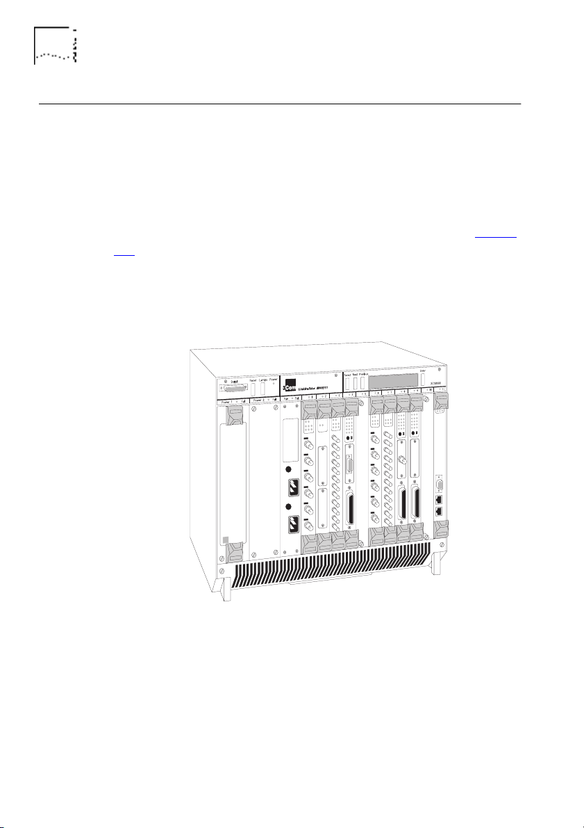
The LinkBuilder MSH is an extremely versatile chassis-based hub,
which enables you to connect and manage large,
mixed-technology, mixed-media LANs.
The basis of the LinkBuilder MSH is the chassis, into which a series
of network specific modules can be installed, as shown in Figure
1-1. The modules within the chassis connect to a backplane. It is
the backplane which allows communication between the various
LANs and LAN segments connected to the LinkBuilder MSH.
Contact your supplier for the latest list of modules available.
Figure 1-1 The LinkBuilder MSH
The LinkBuilder MSH's backplane contains three Ethernet busses.
Ethernet modules can connect to any bus or be independent of
the chassis; this is the versatility of the LinkBuilder MSH.
DUA1860-0AAA01
The LinkBuilder MSH 4 Port Ethernet Bridge Module 1-3
The LinkBuilder MSH 4 Port Ethernet Bridge Module
The bridge module provides a bridge connection between the
three Ethernet busses of the MSH and an external port (the bridge
module's transceiver module), as shown in Figure 1-2
. The
bridge's connections are referred to as ports (1, 2, 3 and E).
Figure 1-2
The Network Segments
1
2
3
E

1-4 C
HAPTER
1: I
NTRODUCTION
DUA1860-0AAA01
The bridge module provides:
■
Connection to each Ethernet bus in the MSH.
■
An external connection by transceiver module.
■
LEDs for indicating bridge activity and diagnosing possible
problems.
■
Standard IEEE 802.1 Part D transparent bridging.
■
Additional custom bridge filtering:
■
Host-to-Host filtering
■
Host-to-Port filtering
■
Port-to-Port filtering
■
Multicast-to-Port filtering
■
Protocol filtering
■
Bit filtering
■
Spanning Tree Algorithm and Protocol (STAP).
DUA1860-0AAA01
The LinkBuilder MSH 4 Port Ethernet Bridge Module 1-5
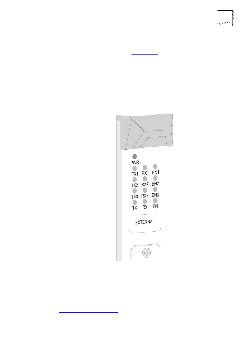
Below its top ejector, the bridge has a panel of LEDs that indicate
bridge activity, as shown in Figure 1-3
.
Each port has a row of three LEDs; transmit (TX), receive (RX) and
enabled (EN). Ports with numbers signify the Ethernet bus in the
LinkBuilder MSH chassis to which the port is connected. The
unnumbered row is for the external port, the Transceiver Module.
Figure 1-3
The Module’s LEDs
You can also use the LEDs to help with diagnosing faults on your
system, for more information refer to
Using The LEDs For Fault
Diagnosis
on page 6-3.
1-6 C
HAPTER
1: I
NTRODUCTION
DUA1860-0AAA01
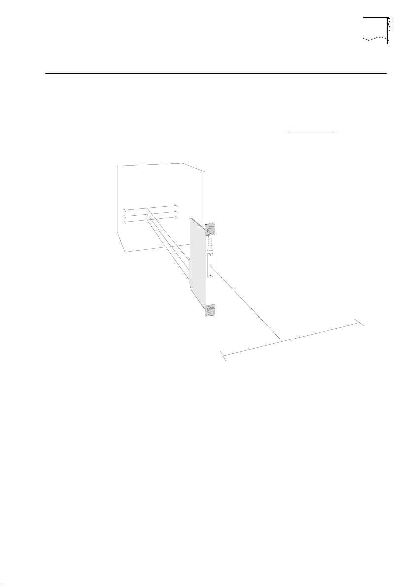
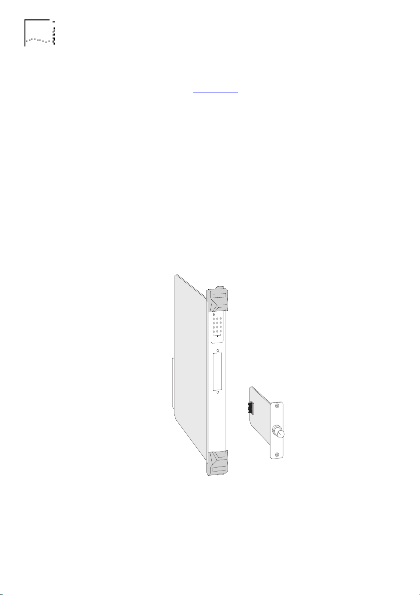
A Transceiver Module can be fitted to the bridge, providing its
fourth port, as shown in Figure 1-4
. A range of Modular
Transceivers are produced by 3Com, allowing you flexibility when
deciding on network connections and cabling:
■
3C12060 Female AUI Transceiver Module
■
3C12065 Fiber Transceiver Module (ST)
■
3C12064 Fan Out Transceiver Module
■
3C12066 Coaxial Transceiver Module
■
3C12060 LinkBuilder Bridge MicroModule
Your supplier will know of any other Transceiver Modules not
listed here.
Figure 1-4 The Transceiver Module
Instructions on how to fit a Transceiver Module are given in the
manual that accompanies it.
DUA1860-0AAA01
Managing The Bridge 1-7
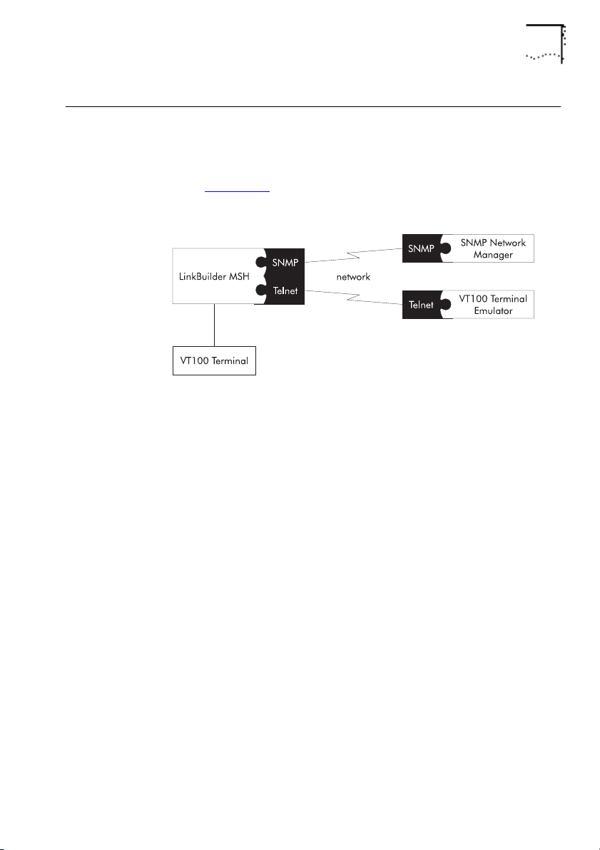
Managing The Bridge
The bridge can be managed using either the VT100 management
interface or remotely via SNMP using a suitable application, as
shown in Figure 1-5
. SNMP provides a subset of the VT100
management facilities.
Figure 1-5
VT100 Management
To use the VT100 management interface:
■
Connect a VT100 terminal or VT100 terminal emulator directly to
the serial port on the display panel of the LinkBuilder MSH.
■
Use a VT100 terminal emulator over a network, via Telnet.
To manage the bridge, you must have a LinkBuilder MSH
Management Module (3C18500) with software version 2.1 or
later installed. If you do not have a Management Module
installed, contact your supplier.
Please refer to
The LinkBuilder MSH Management Module
manuals for information on connecting VT100.

1-8 C
HAPTER
1: I
NTRODUCTION
DUA1860-0AAA01
Bridging
This section describes bridges and how they work.
Why Use A Bridge?
Bridges provide a way of joining two or more networks together
to form a single logical and physical network.
You can overcome various network restrictions that apply to large
individual networks by bridging smaller networks together. The
bridge remains transparent to the users of these networks.
The original networks that form the bridged network are called
network segments
. The bridge learns, from network traffic, what
devices on the network can be reached via each of its ports. It
reduces the amount of traffic on each network segment by
filtering traffic that does not need to be forwarded to it. Standard
filtering is described in
Learning, Filtering And Forwarding
on
page 1-12.
You can also apply custom filters to restrict communication
through the bridge. This allows you to add some security to your
network. Custom filtering is described in
Bridge Filters
on page
1-20.
Resilience can be built into a bridged network. The bridges on the
network can control the flow of traffic throughout the network.
Resilience is described in
Spanning Tree Algorithm And Protocol
(STAP)
on page 1-16.
DUA1860-0AAA01
Bridging 1-9
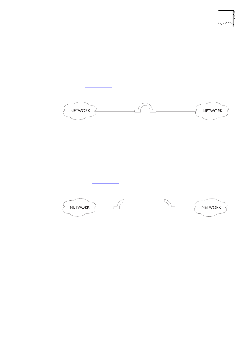
Local And Remote Bridges
There are two main types of bridge,
local
and
remote
. The
LinkBuilder MSH 4 Port Ethernet Bridge Module is a local bridge.
Local bridges are used for bridging networks on the same site, as
shown in Figure 1-6
.
Figure 1-6
Local Bridge
Remote bridges are used for bridging networks across large areas.
A remote bridge is often called a
half
bridge because each
network connects to half of the remote bridge. The remote
bridge halves are connected by a Wide Area Network (WAN) link,
as shown in Figure 1-7
.
Figure 1-7
Remote Bridge
Both types of bridge have essentially the same operation and
functionality.
1-10 C
HAPTER
1: I
NTRODUCTION
DUA1860-0AAA01
Bridge Network Topology
The
topology
of a network is essentially its layout; how its
component parts are inter-connected. The topology of your
network is dependent on the amount of bridges that you use and
the way in which you use them. If you use one 4 Port Ethernet
Bridge Module, you may have a
star
topology.
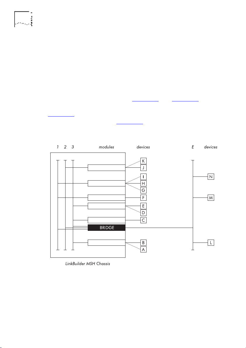
In the example setups shown in Figure 1-8
and Figure 1-9, the
bridge connects all three MSH busses and an external segment.
Figure 1-8
shows how the devices, modules and MSH chassis are
physically connected, and Figure 1-9
shows the resulting
topology.
Figure 1-8 An Example Bridge Setup
DUA1860-0AAA01
Bridging 1-11
Figure 1-9
An Example Topology
1-12 C
HAPTER
1: I
NTRODUCTION
DUA1860-0AAA01
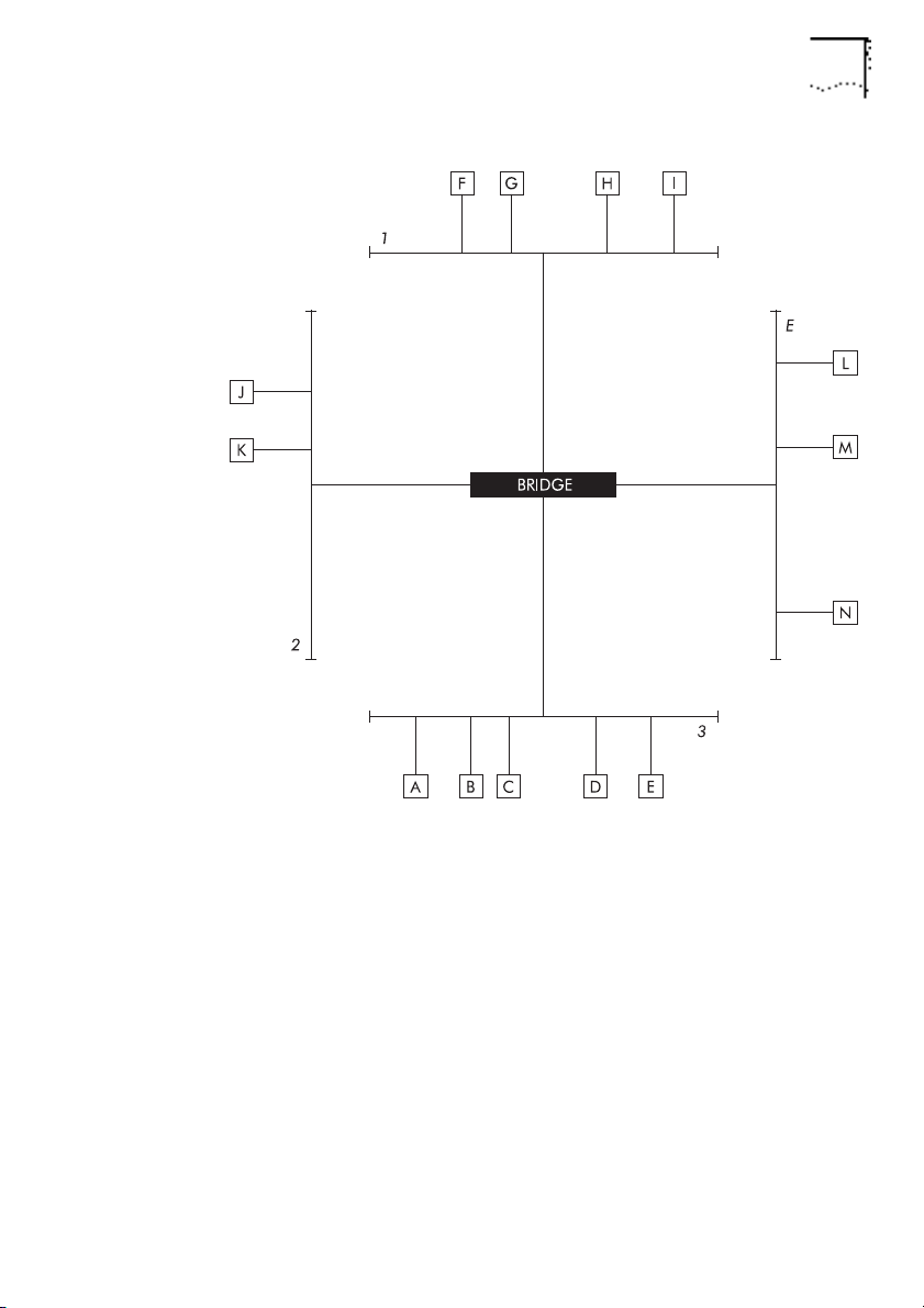
Learning, Filtering And Forwarding
Transparent
bridges remain transparent to the network segments,
treating them as one overall network. The main operations of a
transparent bridge are
learning
,
filtering
and
forwarding
. These
operations are 802.1 bridge features and enable it to control the
flow of traffic to each network segment.
Devices send information as frames. The two main types of frame
are 802.3 and Ethernet. The destination address and source
address are contained within the frame, as shown in Figure 1-10
.
Figure 1-10 Frame Contents
Every time the bridge receives a packet, it looks at the source
address and destination address. If the bridge has not previously
received a packet on that port from the device, it learns the
source address by adding it to a list of device addresses connected
to the port. The bridge then compares the destination address to
the address lists for all the ports on the bridge. If the destination
address appears on the address list of a port that did not receive
the packet, the bridge
forwards
(duplicates) the packet to that
port. If the destination address appears on the address list of the
same port that received the packet, the bridge
filters
(discards)
the packet. If the destination address does not appear on any of
its address lists, the bridge passes it on to all but the receiving
port, called
flooding
.
Destination
Address
802.3 frame
Ethernet frame
Destination
Address
Length
Type
Data
Data
Frame
Checksum
Frame
Checksum
Source
Address
Source
Address
DUA1860-0AAA01
Bridging 1-13
Figure 1-11, Figure 1-12, Figure 1-13 and Figure 1-14 illustrate
how a bridge learns device addresses and uses address lists to
reduce unnecessary network traffic.
Figure 1-11
: The bridge does not know what devices are on the
network.
Figure 1-11
An Example Network
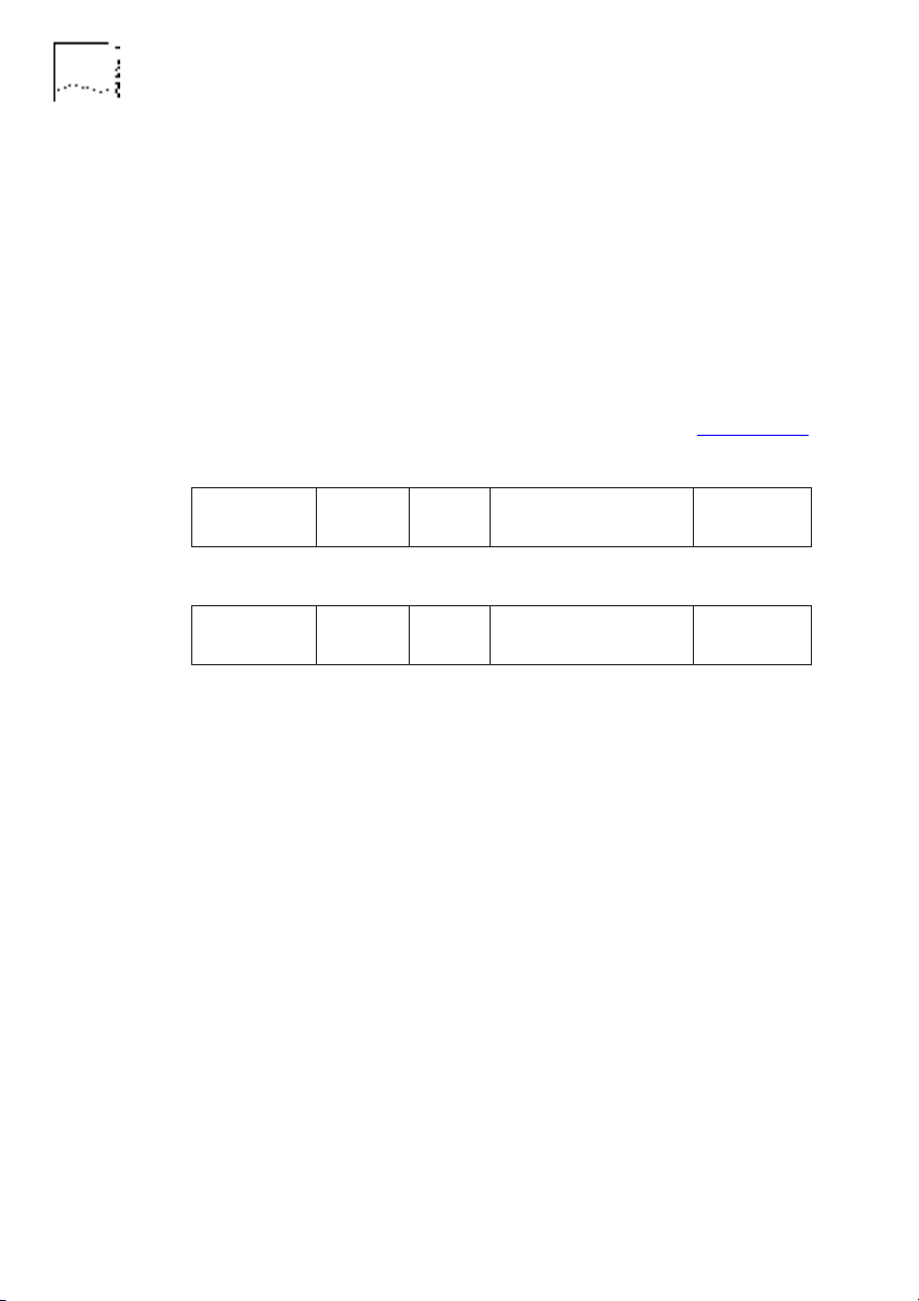
Figure 1-12: Device A, connected to port 1, transmits a packet for
device B. The bridge learns the address of device A but does not
know where device B is, so it passes the packet to ports 2, 3 and
E.
Figure 1-12
Learns A, Passes On Packet
1-14 C
HAPTER
1: I
NTRODUCTION
DUA1860-0AAA01
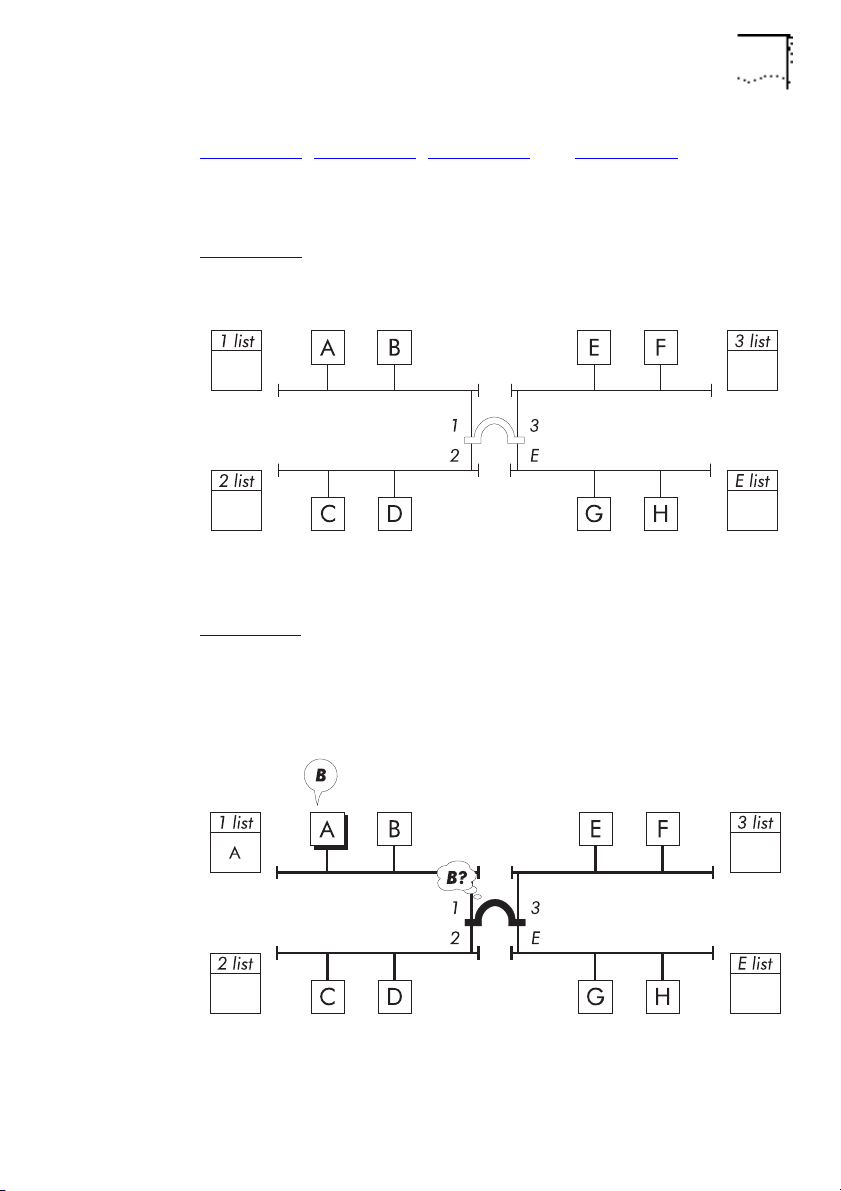
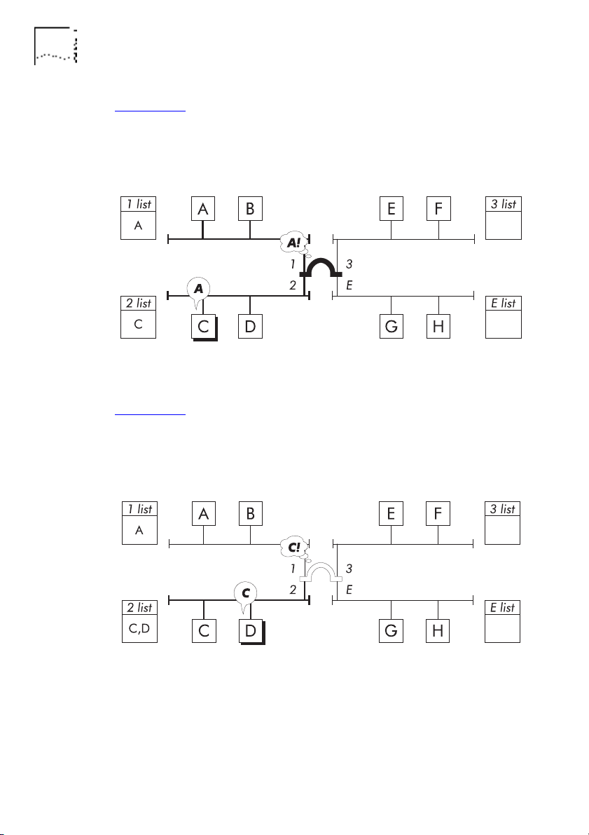
Figure 1-13: Device C, connected to port 2, transmits a packet for
device A. The bridge learns the address of device C and
recognizes the address of device A, so it forwards the packet to
port 1.
Figure 1-13 Learns C, Forwards Packet
Figure 1-14: Device D, connected to port 2, transmits a packet for
device C. The bridge learns the address of device D and
recognizes the address of device C is on the same address list, so
it filters the packet.
Figure 1-14 Learns D, Filters Packet
The bridge can now effectively control network traffic by
forwarding packets only to relevant network segments.

DUA1860-0AAA01
Bridging 1-15
The bridge performs
ageing
on address list entries. If a port has
not received a packet from a device within a configured time (the
ageing time
), the device's address will be removed from the port's
address list. This helps the bridge to efficiently remember devices
that communicate frequently without having to cope with devices
that communicate infrequently or are no longer there.
Because the bridge continually learns new addresses and ages out
old addresses, it does not have to be reconfigured or initialized
when a device is added to the network.
1-16 C
HAPTER
1: I
NTRODUCTION
DUA1860-0AAA01
Spanning Tree Algorithm And Protocol (STAP)
You can make your network more resilient by adding bridges and
network segments. If a network segment or bridge fails, traffic
can still travel through the network by using the additional
bridges and network segments.
The key to resilience is the number of paths through the network.
Multiple paths, however, result in
active loops
. Active loops
introduce redundant traffic to the network, which can quickly
degrade overall network performance and, more importantly,
breaks network rules.
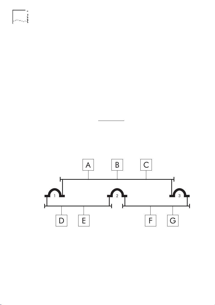
In the example shown in Figure 1-15
, three network segments are
connected by three bridges, causing an active loop. Device B
transmits a packet for device E. Bridges 1 and 3 receive the packet
and forward it. Device E receives the packet from bridge 1 but
also receives a copy from bridge 2 (via bridge 3).
Figure 1-15 An Example Active Loop
A networking standards committee of the Institute of Electronic
and Electrical Engineers (IEEE) recognized and solved the problem
by introducing the
Spanning Tree Algorithm and Protocol
(STAP).
The STAP has become a standard bridge feature.
Loading...