


 Loading...
3Com® Switch 5500 Family
Getting Started Guide
Switch 5500-EI
Switch 5500G-EI
www.3Com.com
Part No. 10014925, Rev. AD
Published: August, 2007
3Com Corporation
350 Campus Drive
Marlborough, MA
USA 01752-3064
Copyright © 2006-2007, 3Com Corporation. All rights reserved. No part of this documentation may be reproduced in any form or by any means or used to make any derivative work (such as translation, transformation, or adaptation) without written permission from 3Com Corporation.
3Com Corporation reserves the right to revise this documentation and to make changes in content from time to time without obligation on the part of 3Com Corporation to provide notification of such revision or change.
3Com Corporation provides this documentation without warranty, term, or condition of any kind, either implied or expressed, including, but not limited to, the implied warranties, terms or conditions of merchantability, satisfactory quality, and fitness for a particular purpose. 3Com may make improvements or changes in the product(s) and/or the program(s) described in this documentation at any time.
If there is any software on removable media described in this documentation, it is furnished under a license agreement included with the product as a separate document, in the hard copy documentation, or on the removable media in a directory file named LICENSE.TXT or !LICENSE.TXT. If you are unable to locate a copy, please contact 3Com and a copy will be provided to you.
UNITED STATES GOVERNMENT LEGEND
If you are a United States government agency, then this documentation and the software described herein are provided to you subject to the following:
All technical data and computer software are commercial in nature and developed solely at private expense. Software is delivered as “Commercial Computer Software” as defined in DFARS 252.227-7014 (June 1995) or as a “commercial item” as defined in FAR 2.101(a) and as such is provided with only such rights as are provided in 3Com’s standard commercial license for the Software. Technical data is provided with limited rights only as provided in DFAR 252.227-7015 (Nov 1995) or FAR 52.227-14 (June 1987), whichever is applicable. You agree not to remove or deface any portion of any legend provided on any licensed program or documentation contained in, or delivered to you in conjunction with, this User Guide.
Unless otherwise indicated, 3Com registered trademarks are registered in the United States and may or may not be registered in other countries.
3Com and the 3Com logo are registered trademarks of 3Com Corporation.
Cisco is a registered trademark of Cisco Systems, Inc.
Funk RADIUS is a registered trademark of Funk Software, Inc.
Aegis is a registered trademark of Aegis Group PLC.
Intel and Pentium are registered trademarks of Intel Corporation. Microsoft, MS-DOS, Windows, and Windows NT are registered trademarks of Microsoft Corporation. Novell and NetWare are registered trademarks of Novell, Inc. UNIX is a registered trademark in the United States and other countries, licensed exclusively through X/Open Company, Ltd.
IEEE and 802 are registered trademarks of the Institute of Electrical and Electronics Engineers, Inc.
All other company and product names may be trademarks of the respective companies with which they are associated.
ENVIRONMENTAL STATEMENT
It is the policy of 3Com Corporation to be environmentally-friendly in all operations. To uphold our policy, we are committed to:
Establishing environmental performance standards that comply with national legislation and regulations.
Conserving energy, materials and natural resources in all operations.
Reducing the waste generated by all operations. Ensuring that all waste conforms to recognized environmental standards. Maximizing the recyclable and reusable content of all products.
Ensuring that all products can be recycled, reused and disposed of safely.
Ensuring that all products are labelled according to recognized environmental standards.
Improving our environmental record on a continual basis.
End of Life Statement
3Com processes allow for the recovery, reclamation and safe disposal of all end-of-life electronic components.
Regulated Materials Statement
3Com products do not contain any hazardous or ozone-depleting material.

CONTENTS
ABOUT THIS GUIDE
Release Notes |
8 |
|
Conventions |
8 |
|
Related Documentation 8 |
|
|
Accessing the Documentation |
9 |
|
Documentation Comments |
10 |
|
1INTRODUCING THE SWITCH 5500 FAMILY
|
About the Switch 5500 Family 12 |
|
|||
|
Switch 5500 Family — Front View |
14 |
|
||
|
Switch 5500 — Rear View Detail |
21 |
|
||
|
Default Settings |
27 |
|
|
|
|
|
|
|
||
2 INSTALLING THE SWITCH |
|
|
|||
|
Package Contents |
30 |
|
|
|
|
Choosing a Suitable Site |
31 |
|
|
|
|
Rack-mounting |
32 |
|
|
|
|
Connecting a Redundant Power Supply |
35 |
|||
|
Installing and Removing the Power Module 42 |
||||
|
Placing Units On Top of Each Other 43 |
|
|||
|
The Power-up Sequence |
43 |
|
|
|
|
SFP Operation 47 |
|
|
|
|
|
Installing and Removing the Optional Interface Module 50 |
||||
|
Packing and Shipping the Switch 5500 |
51 |
|||
|
|
|
|||
3 SETTING UP FOR MANAGEMENT |
|
||||
|
Methods of Managing a Switch |
56 |
|
||
|
Setting Up Your Switch |
58 |
|
|
|
|
Manually Configuring the IP Information |
61 |
|
|||
|
Viewing Automatically Configured IP Information |
67 |
||||
|
Setting Up Command Line Interface Management |
69 |
||||
|
Setting Up Command Line Interface Management using SSH 70 |
|||||
|
Setting Up Web Interface Management |
71 |
|
|||
|
Setting Up SNMP Management |
72 |
|
|
||
|
Changing the Default Passwords |
73 |
|
|
||
|
Downloading the Configuration Conversion Utility |
74 |
||||
4 |
|
|
||||
CREATING AN XRN STACKING FABRIC |
|
|||||
|
How To Interconnect Units |
75 |
|
|
|
|
|
Guidelines For Interconnecting Units |
78 |
|
|||
|
Unit Numbering within the Fabric |
|
78 |
|
|
|
5 |
|
|
|
|
|
|
PROBLEM SOLVING |
|
|
|
|
|
|
|
Solving Problems Indicated by LEDs |
82 |
|
|||
|
Solving Hardware Problems |
83 |
|
|
|
|
|
Solving Communication Problems |
|
84 |
|
|
|
|
Solving Fabric Formation Problems |
|
86 |
|
|
|
6 |
|
|
|
|
|
|
UPGRADING SOFTWARE |
|
|
|
|
|
|
|
The Contents of the Executable File |
88 |
|
|||
|
Upgrading from the Command Line Interface 88 |
|
||||
|
Upgrading from the Bootrom Interface |
95 |
|
|||
|
Bootrom Upgrade 99 |
|
|
|
|
|
A |
|
|
|
|
|
|
SAFETY INFORMATION |
|
|
|
|
|
|
|
Power Cord Set — Japan 104 |
|
|
|
|
|
|
Important Safety Information |
104 |
|
|
|
|
|
L’information de Sécurité Importante |
107 |
|
|||
|
Wichtige Sicherheitsinformationen |
|
110 |
|
||
|
Información de Seguridad Importante |
112 |
|
|||
|
Importanti Informazioni di Sicurezza |
115 |
|
|||
|
Wa¿ne informacje o zabezpieczeniach |
118 |
|
|||

B |
PIN-OUTS |
|
|
|
|
|
|
Null Modem Cable |
123 |
|
|
|
|
|
PC-AT Serial Cable 123 |
|
|
|
||
|
Modem Cable |
124 |
|
|
|
|
|
Ethernet Port RJ-45 Pin Assignments |
124 |
||||
C |
|
|
|
|||
TECHNICAL SPECIFICATIONS |
|
|
||||
|
Switch 5500 (28 Port) |
128 |
|
|
||
|
Switch 5500 PWR (28 Port) |
129 |
|
|||
|
Switch 5500 (52 Port) |
130 |
|
|
||
|
Switch 5500 PWR (52 Port) |
131 |
|
|||
|
Switch 5500 FX (28 Port) |
132 |
|
|
||
|
Switch 5500G-EI (24 Port) |
133 |
|
|
||
|
Switch 5500G-EI PWR (24 Port) |
134 |
|
|||
|
Switch 5500G-EI (48 Port) |
135 |
|
|
||
|
Switch 5500G-EI PWR (48 Port) |
136 |
|
|||
|
Switch 5500G-EI SFP (24-Port) |
137 |
|
|||
|
RPS 138 |
|
|
|
|
|
|
Earthing Lead |
139 |
|
|
|
|
D |
|
|||||
OBTAINING SUPPORT FOR YOUR PRODUCT |
||||||
|
Register Your Product |
141 |
|
|
||
|
Purchase Value-Added Services |
141 |
|
|||
|
Troubleshoot Online |
142 |
|
|
|
|
|
Access Software Downloads |
142 |
|
|||
|
Telephone Technical Support and Repair 142 |
|||||
|
Contact Us |
143 |
|
|
|
|
E |
|
|||||
3COM NETWORK MANAGEMENT |
||||||
|
3Com Network Supervisor |
145 |
|
|||
|
3Com Network Director 146 |
|
|
|||
|
3Com Network Access Manager |
146 |
|
|||
|
3Com Enterprise Management Suite |
147 |
||||
Integration Kit with HP OpenView Network Node Manager 147

INDEX
REGULATORY NOTICES

ABOUT THIS GUIDE
This guide provides all the information you need to install and use the following switches in their default state:
Table 1 Switch 5500 Family
Switch Model |
SKU Number |
|
|
|
|
Switch 5500-SI 28-Port |
3CR17151-91 |
|
|
|
|
Switch 5500-SI 52-Port |
3CR17152-91 |
|
|
|
|
Switch 5500-EI 28-Port |
3CR17161-91 |
|
|
|
|
Switch 5500-EI 52-Port |
3CR17162-91 |
|
|
|
|
Switch 5500-EI PWR 28-Port |
3CR17171-91 |
|
|
|
|
Switch 5500-EI PWR 52-Port |
3CR17172-91 |
|
|
|
|
Switch 5500-EI 28-Port FX |
3CR17181-91 |
|
|
|
|
Switch 5500G-EI 24-Port |
3CR17250-91 |
Includes 3CR17254-91 (chassis) |
|
|
and 3C17266 (power supply) |
|
|
|
Switch 5500G-EI 48-Port |
3CR17251-91 |
Includes 3CR17255-91 (chassis) |
|
|
and 3C17267 (power supply) |
|
|
|
Switch 5500G-EI PWR 24-Port |
3CR17252-91 |
Includes 3CR17254-91 (chassis) |
|
|
and 3C17264 (power supply) |
|
|
|
Switch 5500G-EI PWR 48-Port |
3CR17253-91 |
Includes 3CR17255-91 (chassis) |
|
|
and 3C17265 (power supply) |
|
|
|
Switch 5500G-EI 24-Port SFP |
3CR17258-91 |
Includes 3CR17259-91 (chassis) |
|
|
and 3C17266 (power supply) |
|
|
|
All procedures described in this guide apply to all models except where stated.
The guide is intended for network administrators who are responsible for installing and setting up network equipment; consequently, it assumes a basic working knowledge of LANs (Local Area Networks).

8 ABOUT THIS GUIDE
Release Notes |
The Release Notes provide important information about the current |
||
|
software release, including new features, modifications, and known |
||
|
problems. You should read the Release Notes before installing the Switch |
||
|
in your network. |
|
|
|
If the information in the Release Notes differs from the information in this |
||
|
guide, follow the instructions in the Release Notes. |
||
|
|
||
Conventions |
Table 2 lists conventions that are used throughout this guide. |
||
|
Table 2 |
Notice Icons |
|
|
|
|
|
|
Icon |
Notice Type |
Description |
|
|
|
|
|
|
Information note |
Information that describes important features or |
|
|
|
instructions |
|
|
Caution |
Information that alerts you to potential data loss or |
|
|
|
potential damage to an application, system, or device |
|
|
Warning |
Information that alerts you to potential personal injury |
|
|
||
|
|
|
|
Related |
In addition to this guide, each Switch documentation set includes the |
||
Documentation |
following: |
|
|
■ Switch 5500 Family Configuration Guide
This guide contains information about the features supported by your
Switch and how you can use them to optimize your network.
■ Switch 5500 Family Quick Reference Guide
This guide contains a list of the features supported by the Switch 5500 Family and a summary of the command line interface commands available for the Switch. This guide is also available under the Help button on the web interface.
■ Switch 5500 Family Command Reference Guide
This guide provides detailed information about the web interface and command line interface that enable you to manage the Switch.

|
Accessing the Documentation 9 |
|
■ Release Notes |
|
These notes provide information about the current software release, |
|
including new features, modifications, and known problems. The |
|
Release Notes are supplied in hard copy with your Switch. |
|
|
Accessing the |
The Switch 5500 Family documentation is available in Adobe Acrobat |
Documentation |
Reader Portable Document Format (PDF) at www.3com.com. |

10 ABOUT THIS GUIDE
Documentation |
Your suggestions are very important to us. They will help make our |
Comments |
documentation more useful to you. Please e-mail comments about this |
|
document to 3Com at: |
|
pddtechpubs_comments@3com.com |
|
Please include the following information when commenting: |
|
■ Document title |
|
■ Document part number and revision (on the title page) |
|
■ Page number (if appropriate) |
|
Example: |
|
Part Number 10014925 rev. AC |
|
Switch 5500 Family Getting Started Guide |
|
Page 21 |
|
Please note that we can only respond to comments and questions about |
|
3Com product documentation at this e-mail address. Questions related |
|
to technical support or sales should be directed in the first instance to |
|
your network supplier. |
1 |
INTRODUCING THE |
|
|
|
SWITCH 5500 FAMILY |
This chapter contains introductory information about the Switch 5500 and how it to use it within a network. It includes hardware and software feature summaries and contains the following section:
■About the Switch 5500 Family
■Switch 5500 Family — Front View
■Switch 5500 — Rear View Detail
■Default Settings

12 CHAPTER 1: INTRODUCING THE SWITCH 5500 FAMILY
About the Switch |
The Switch 5500 Family includes mixed media devices consisting of those |
|||||||||
5500 Family |
described in Table 3. |
|
|
|
|
|
|
|
|
|
|
Table 3 Switch 5500 Family Hardware |
|
|
|
|
|
|
|
||
|
|
|
|
|
|
|
|
|
|
|
|
Switch 5500 Family |
10BASE-T\100BASE-TX Ports |
10BASE-T\1000BASE-TX\1000BASE-T Ports |
10\100\1000 PoE Ports |
100BASE-X SFP Ports |
1000BASE-X SFP Ports |
Stacking Ports |
RJ-45 Console Port |
-48V DC RPS Input |
Module Slot |
|
|
|
|
|
|
|
|
|
|
|
|
Switch 5500-SI 28 Port |
24 |
|
|
|
4 |
|
1 |
1 |
|
|
|
|
|
|
|
|
|
|
|
|
|
Switch 5500-SI 52 Port |
48 |
|
|
|
4 |
|
1 |
1 |
|
|
|
|
|
|
|
|
|
|
|
|
|
Switch 5500-EI 28 Port |
24 |
|
|
|
4 |
|
1 |
1 |
|
|
|
|
|
|
|
|
|
|
|
|
|
Switch 5500-EI 52 Port |
48 |
|
|
|
4 |
|
1 |
1 |
|
|
|
|
|
|
|
|
|
|
|
|
|
Switch 5500 PWR 28 Port |
|
|
24 |
|
4 |
|
1 |
1 |
|
|
|
|
|
|
|
|
|
|
|
|
|
Switch 5500 PWR 52 Port |
|
|
48 |
|
4 |
|
1 |
1 |
|
|
|
|
|
|
|
|
|
|
|
|
|
Switch 5500 FX 28 Port |
|
2 |
|
24 |
2 |
|
1 |
1 |
|
|
|
|
|
|
|
|
|
|
|
|
|
Switch 5500G-EI 24 Port |
|
24 |
24* |
|
4† |
2 |
1 |
1 |
1 |
|
|
|
|
|
|
|
|
|
|
|
|
Switch 5500G-EI 48 Port |
|
48 |
48* |
|
4† |
2 |
1 |
1 |
1 |
|
|
|
|
|
|
|
|
|
|
|
|
Switch 5500G-EI SFP 24 Port |
|
4 |
|
|
24 |
2 |
1 |
1 |
1 |
|
|
|
|
|
|
|
|
|
|
|
*Depending on Power Supply Unit Fitted
†Combo SFP and 10/100/100 Ports
The Switch 5500 Family provides high-performance workgroups with a backbone to the server connection. You can also add the Switch 5500 to any 3Com system as your network grows.

About the Switch 5500 Family 13
For information about using the software features of the Switch, refer to the “Command Reference Guide” located at www.3com.com.
Summary of Table 4 summarizes the hardware features that are supported by the
Hardware Features Switch 5500.
Table 4 Hardware Features
Feature |
Switch 5500 Family |
|
|
MAC Addresses |
Up to 16,000 supported |
Forwarding Modes |
Store and Forward |
Auto-negotiation |
Supported on all ports |
Auto MDI/MDIX |
Supported on all ports. If fiber SFP transceivers are |
|
used, Auto MDIX is not supported. |
Duplex Modes |
Half and full duplex on all ports |
Flow Control |
In full duplex mode, all ports are supported. |
Smart Auto-sensing |
Supported on all copper ports |
Traffic Prioritization |
Supported (IEEE Std 802.1D, 1998 Edition) |
|
Eight traffic queues per port |
Power over Ethernet |
Supported on front panel ports, except for the SFP |
(Switch 5500) |
ports. (3CR17171 and 3CR17172 only) |
Power over Ethernet |
Supported on all front panel ports, except for the |
(Switch 5500G-EI) |
SFP ports, when fitted with PoE PSUs (3CR17254 |
|
and 3CR17255). |
Ethernet and Fast Ethernet |
Auto-negotiating 10BASE-T/100BASE-TX ports or |
Ports |
100BASE-X ports. |
(Switch 5500) |
|
Fast Ethernet and Gigabit |
Auto-negotiating |
Ethernet Ports (Switch |
10BASE-T/100BASE-TX/1000BASE-T and SFP ports. |
5500G-EI) |
|
100BASE-X SFP Ports |
Supports 100BASE-LX10 10km single-mode and |
|
100BASE-FX 2km multi-mode transceivers. |
1000BASE-X Gigabit |
Supports fiber Gigabit Ethernet short-wave (SX), |
Ethernet SFP Ports |
long-wave (LX), long-haul (LH70), and copper (T) |
|
transceivers in any combination |
|
|

14 CHAPTER 1: INTRODUCING THE SWITCH 5500 FAMILY
Switch 5500 Family
— Front View
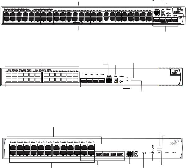
Figure 1 Switch 5500-SI and EI 28-Port — front view
|
|
|
|
|
|
|
|
|
|
|
|
|
|
Port Status LEDs |
|
|
|
|
|
|
|
|
|
|
Console Port |
RPS LED |
|||||||||||||||||||||||||||||||||
|
|
|
|
|
|
|
|
|
|
|
|
|
|
|
|
|
|
|
|
|
|
|
|
|
|
|
|
|
|
|
|
|
|
|
|
|
|
|
|
|
|
|
|
|
|
|
|
|
|
|
|
|
|
|
|
|
|
|
|
|
|
|
|
|
|
|
|
|
|
|
|
|
|
|
|
|
|
|
|
|
|
|
|
|
|
|
|
|
|
|
|
|
|
|
|
|
|
|
|
|
|
|
|
|
|
|
|
|
|
|
|
|
|
|
|
|
|
|
|
|
|
|
|
|
|
|
|
|
|
|
|
|
|
|
|
|
|
|
|
|
|
|
|
|
|
|
|
|
|
|
|
|
|
|
|
|
|
|
|
|
|
|
|
|
|
|
|
|
|
|
|
|
|
|
|
|
|
|
|
|
|
|
|
|
|
|
|
|
|
|
|
|
|
|
|
|
|
|
|
|
|
|
|
|
|
|
|
|
|
|
|
|
|
|
|
|
|
|
|
|
|
|
|
|
|
|
|
|
|
|
|
|
|
|
|
|
|
|
|
|
|
|
|
|
|
|
|
|
|
|
|
|
|
|
|
|
|
|
|
|
|
|
|
|
|
|
|
|
|
|
|
|
|
|
|
|
|
|
|
|
|
|
|
|
|
|
|
|
|
|
|
|
|
|
|
|
|
|
|
|
|
|
|
|
|
|
|
|
|
|
|
|
|
|
|
|
|
|
|
|
|
|
|
|
|
|
|
|
|
|
|
|
|
|
|
|
|
|
|
|
|
|
|
|
|
|
|
|
|
|
|
|
|
|
|
|
|
|
|
|
|
|
|
|
|
|
|
|
|
|
|
|
|
|
|
|
|
|
|
|
|
|
|
|
|
|
|
|
|
|
|
|
|
|
|
|
|
|
|
|
|
|
|
|
|
|
|
|
|
|
|
|
|
|
|
|
|
|
|
|
|
|
|
|
|
|
|
|
|
|
|
|
|
|
|
|
|
|
|
|
|
|
|
|
|
|
|
|
|
|
|
|
|
|
|
|
|
|
|
|
|
|
|
|
|
|
|
|
|
|
|
|
|
|
|
|
|
|
|
|
|
|
|
|
|
|
|
|
|
|
|
|
10/100BASE-TX Ports |
|
|
|
|
|
|
1000BASE-X Ports |
|
|
|
|
|
|
Unit LED Mode LED Power LED |
|
|
|
|
|
|
|
|
|
||||||||||||||||||||||||||||||||||||||
|
|
|
|
|
|
|
|
|
|
|
|
|
|
|
|
|
|
|
|
Figure 2 Switch 5500-SI and EI 52-Port — front view |
|
|
|
|
|
|
|
|
|
|||||||||||||||||||||||||||||||||||||||||||||
|
|
|
|
|
|
|
|
|
|
|
|
|
|
|
|
|
|
|
|
|
|
|
|
|
|
Port Status LEDs |
|
|
|
|
|
|
|
|
|
|
|
|
|
|
|
|
Console Port |
Unit LED |
|
|
|
|
|
RPS LED |
||||||||||||||||||||||||
|
|
|
|
|
|
|
|
|
|
|
|
|
|
|
|
|
|
|
|
|
|
|
|
|
|
|
|
|
|
|
|
|
|
|
|
|
|
|
|
|
|
|
|
|
|
|
|
|
|
|
|
|
|
|
|
|
|
|
|
|
|
|
|
|
|
|
Mode LED |
|||||||
|
|
|
|
|
|
|
|
|
|
|
|
|
|
|
|
|
|
|
|
|
|
|
|
|
|
|
|
|
|
|
|
|
|
|
|
|
|
|
|
|
|
|
|
|
|
|
|
|
|
|
|
|
|
|
|
|
|
|
|
|
|
|
|
|
|
|||||||||
|
|
|
|
|
|
|
|
|
|
|
|
|
|
|
|
|
|
|
|
|
|
|
|
|
|
|
|
|
|
|
|
|
|
|
|
|
|
|
|
|
|
|
|
|
|
|
|
|
|
|
|
|
|
|
|
|
|
|
|
|
|
|
|
|
|
|
|
|
|
|
|
|
|
|
|
|
|
|
|
|
|
|
|
|
|
|
|
|
|
|
|
|
|
|
|
|
|
|
|
|
|
|
|
|
|
|
|
|
|
|
|
|
|
|
|
|
|
|
|
|
|
|
|
|
|
|
|
|
|
|
|
|
|
|
|
|
|
|
|
|
|
|
|
|
|
|
|
|
|
|
|
|
|
|
|
|
|
|
|
|
|
|
|
|
|
|
|
|
|
|
|
|
|
|
|
|
|
|
|
|
|
|
|
|
|
|
|
|
|
|
|
|
|
|
|
|
|
|
|
|
|
|
|
|
|
|
|
|
|
|
|
|
|
|
|
|
|
|
|
|
|
|
|
|
|
|
|
|
|
|
|
|
|
|
|
|
|
|
|
|
|
|
|
|
|
|
|
|
|
|
|
|
|
|
|
|
|
|
|
|
|
|
|
|
|
|
|
|
|
|
|
|
|
|
|
|
|
|
|
|
|
|
|
|
|
|
|
|
|
|
|
|
|
|
|
|
|
|
|
|
|
|
|
|
|
|
|
|
|
|
|
|
|
|
|
|
|
|
|
|
|
|
|
|
|
|
|
|
|
|
|
|
|
|
|
|
|
|
|
|
|
|
|
|
|
|
|
|
|
|
|
|
|
|
|
|
|
|
|
|
|
|
|
|
|
|
|
|
|
|
|
|
|
|
|
|
|
|
|
|
|
|
|
|
|
|
|
|
|
|
|
|
|
|
|
|
|
|
|
|
|
|
|
|
|
|
|
|
|
|
|
|
|
|
|
|
|
|
|
|
|
|
|
|
|
|
|
|
|
|
|
|
|
|
|
|
|
|
|
|
|
|
|
|
|
|
|
|
|
|
|
|
|
|
|
|
|
|
|
|
|
|
|
|
|
|
|
|
|
|
|
|
|
|
|
|
|
|
|
|
|
|
|
|
|
|
|
|
|
|
|
|
|
|
|
|
|
|
|
|
|
|
|
|
|
|
|
|
|
|
|
|
|
|
|
|
|
|
|
|
|
|
|
|
|
|
|
|
|
|
|
|
|
|
|
|
|
|
|
|
|
|
|
|
|
|
|
|
|
|
|
|
|
|
|
|
|
|
|
|
|
|
|
|
|
|
|
|
|
|
|
|
|
|
|
|
|
|
|
|
|
|
|
|
|
|
|
|
|
|
|
|
|
|
|
|
|
|
|
|
|
|
|
|
|
|
|
|
|
|
|
|
|
|
|
|
|
|
|
|
|
|
|
|
|
|
|
|
|
|
|
|
|
|
|
|
|
|
|
|
|
|
|
|
|
|
|
|
|
|
|
|
|
|
|
|
|
|
|
|
|
|
|
|
|
|
|
|
|
|
|
|
|
|
PWR LED
|
10/100BASE-TX Ports |
|
1000BASE-X Ports |
|
|
|
|
Figure 3 Switch 5500-EI 28-Port PWR - front view |
|||
Port Status LEDs |
|
Console Port |
RPS LED |
|
|
3CR17171-91 SuperStack 4 Switch 5500 PWR 28 Port |
|
|
|
Green=Status |
|
|
|
Yellow=Packet |
|
|
|
Red=PoE |
|
10/100BASE-TX Ports |
1000BASE-X Ports |
Unit LED |
Mode LED Power LED |
|
Switch 5500 Family — Front View |
15 |
|
Figure 4 Switch 5500-EI 52-Port PWR - front view |
|
||
Port Status LEDs |
|
Console Port Unit LED |
RPS LED |
|
|
Mode LED |
|
|
3CR17172-91 SuperStack 4 Switch 5500 PWR 52 Port |
|
|
|
|
Green=Status |
|
|
|
Yellow=Packet |
|
|
|
Red=PoE |
|
10/100BASE-TX Ports |
|
|
PWR LED |
|
1000BASE-X Ports |
||
|
|
||
Figure 5 Switch 5500-EI FX 28-Port — front view |
|
||
Port Status LEDs |
Console Port |
RPS LED |
|
Unit LED |
|
||
|
|
|
|
Speed |
Duplex |
Green=Speed |
RPS |
Yellow=Duplex |
PWR |
|
100Base-FX |
1000Base-X |
|
|
|
|
|
|
|
|
Power LED |
|
|
|
|
|
|
|
|
|
|
|
100BASE-X Ports |
Two 10/100/1000BASE-T Ports |
|
|
||||||
Mode LED |
|
||||||||
|
|
Two 1000BASE-X Ports |
|
||||||
|
|
|
|
|
|||||
Switch 5500G-EI Figure 6 |
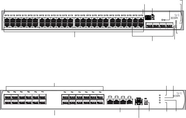
Switch 5500G-EI (24 port) — front view |
|
|||||||
Port Status LEDs |
|
|
|
|
|
|
|
|
|
|
|
|
|
|
|
|
|
Unit LED |
PWR LED |
|
|
|
|
|
|
|
|
|
|
RPS LED
Status:Green=10Mbps Yellow=10Mbps Flashing=Disabled Packet:Green=Full Duplex Yellow=Half Duplex Power:Green=Delivering Power Yellow=Fault Flashing Green=Over Budget |
|
|
|
|
|
|
3CR17251-91 SuperStack 4 Switch 5500G-EI 24-Port |
||||||||||||||||||||||||
1 |
13 |
2 |
14 |
3 |
15 |
4 |
16 |
5 |
17 |
6 |
18 |
7 |
19 |
8 |
20 |
9 |
21 |
10 |
22 |
11 |
23 |
12 |
24 |
|
|
|
|
|
|
|
|
|
|
|
|
|
|
|
|
|
|
|
|
|
|
|
|
|
|
|
|
|
|
|
|
|
|
|
|
|
|
Mode: |
PWR |
|
|
|
|
|
|
|
|
|
|
|
|
|
|
|
|
|
|
|
|
|
|
|
|
|
|
|
|
|
|
|
|
|
|
|
|
|
|
|
|
|
|
|
|
|
|
|
|
|
|
|
|
|
|
|
21 |
|
|
24 |
Console |
Unit |
100% |
Green=Status |
RPS |
|
|
|
|
|
|
|
|
|
|
|
|
|
|
|
|
|
|
|
|
|
|
|
22 |
23 |
|
80% |
Yellow=Packet |
|
|||
|
|
|
|
|
|
|
|
|
|
|
|
|
|
|
|
|
|
|
|
|
|
|
|
|
|
|
|
|
MOD |
||
|
|
|
|
|
|
|
|
|
|
|
|
|
|
|
|
|
|
|
|
|
|
|
|
|
|
|
|
|
60% |
Red=POE |
|
|
|
|
|
|
|
|
|
|
|
|
|
|
|
|
|
|
|
|
|
|
|
|
|
|
|
|
|
|
|
||
|
|
|
|
|
|
|
|
|
|
|
|
|
|
|
|
|
|
|
|
|
|
|
|
|
|
|
|
|
40% |
|
STK |
|
|
|
|
|
|
|
|
|
|
|
|
|
|
|
|
|
|
|
|
|
|
|
|
|
|
|
|
|
20% |
|
|
Stack LED
|
Dual Personality |
Console Port |
Module LED |
10/100/1000BASE-T Ports |
10/100/1000BASE-T/ |
Mode LED |
|
|
1000BASE-X SFP Ports |
|
|
16 CHAPTER 1: INTRODUCING THE SWITCH 5500 FAMILY
Figure 7 Switch 5500G-EI (48 port) — front view
Port Status LEDs |
Console Port |
RPS LED |
|||
Power LED |
|||||
|
|
|
Unit LED |
||
|
|
|
Mode LED |
||
|
|
|
|
||
|
Status:Green=10Mbps Yellow=10Mbps Flashing=Disabled Packet:Green=Full Duplex Yellow=Half Duplex Power:Green=Delivering Power Yellow=Fault Flashing Green=Over Budget |
|
|
|
|
|
|
|
|
SuperStack 4 Switch 5500G-EI 48-port |
|
|
|||||||||||||||||||||||||||||||||||||
|
|
|
|
|
|
|
|
|
|
|
|
|
|
|
|
|
|
|
|
|
|
|
|
|
|
|
|
|
|
|
|
|
|
|
|
|
|
|
|
|
|
|
|
|
|
|
|
100% |
Mode: |
1 |
13 |
2 |
14 |
3 |
15 |
4 |
16 |
5 |
17 |
6 |
18 |
7 |
19 |
8 |
20 |
9 |
21 |
10 |
22 |
11 |
23 |
12 |
24 |
25 |
37 |
26 |
38 |
27 |
39 |
28 |
40 |
29 |
41 |
30 |
42 |
31 |
43 |
32 |
44 |
33 |
45 |
34 |
46 |
35 |
47 |
36 |
48 |
Green=Status |
|
|
|
|
|
|
|
|
|
|
|
|
|
|
|
|
|
|
|
|
|
|
|
|
|
|
|
|
|
|
|
|
|
|
|
|
|
|
|
|
|
|
|
|
|
|
|
|
|
80% |
|
|
|
|
|
|
|
|
|
|
|
|
|
|
|
|
|
|
|
|
|
|
|
|
|
|
|
|
|
|
|
|
|
|
|
|
|
|
|
|
|
|
|
|
|
|
|
|
|
60% |
Yellow=Packet |
|
|
|
|
|
|
|
|
|
|
|
|
|
|
|
|
|
|
|
|
|
|
|
|
|
|
|
|
|
|
|
|
|
|
|
|
|
|
|
|
|
|
|
|
|
|
|
|
40% |
Red=POE |
|
|
|
|
|
|
|
|
|
|
|
|
|
|
|
|
|
|
|
|
|
|
|
|
|
|
|
|
|
|
|
|
|
|
|
|
|
|
|
|
|
|
|
|
|
|
|
|
20% |
|
45 |
46 |
47 |
48 |
PWR |
|
|
|
|
RPS |
|
|
|
|
MOD |
|
|
|
|
STK |
Stack
LED
10/100/1000BASE-T Ports |
Dual Personality |
Module LED |
|
||
|
|
|
|
10/100/1000BASE-T/ |
|
|
1000BASE-X SFP Ports |
|
Figure 8 Switch 5500G-EI SFP (24 port) — front view
Port Status LEDs
Power LED |
|
RPS LED |
|
|
13 |
1 |
14 |
2 |
15 |
3 |
16 |
4 |
17 |
5 |
18 |
6 |
19 |
7 |
20 |
8 |
21 |
9 |
22 |
10 |
23 |
11 |
24 |
12 |
|
|
|
|
3CR17259-91 SuperStack 4 Switch 5500G-EI SFP 24-Port |
|
|||
|
|
|
|
|
|
|
|
|
|
|
|
1000BASE-X: |
|
|
|
|
|
|
|
|
|
|
|
25/11 |
26/12 |
27/23 |
28/24 |
PWR |
||||
|
|
|
|
|
|
|
|
|
|
|
|
Green=1000Mbps Flashing Yellow=POST failed |
|
|
|
|
|
|
|
|
|
|
|
S |
D |
S |
D |
S |
D |
S |
D |
|
|
|
|
|
|
|
|
|
|
|
|
|
10/100/1000BASE-TX: |
|
|
|
|
|
|
|
|
|
|
|
RPS |
||||||||
|
|
|
|
|
|
|
|
|
|
|
|
S(Speed):Green=1000Mbps Yellow=10/100Mbps |
|
|
|
|
|
|
|
|
|
|
|
|
|
|
|
|
|
|
|
|
|
|
|
|
|
|
|
|
|
|
|
|
D(Duplex):Green=Full Duplex Yellow=Half Duplex |
|
|
|
|
|
|
|
|
|
|
|
|
|
|
|
|
|
|
|
STK |
|
|
|
|
|
|
|
|
|
|
|
|
|
|
|
|
|
|
|
|
|
|
|
|
|
|
|
|
|
|
|
|
|
MOD
|
1000Base-X |
|
1000Base-X |
|
10/100/1000Base-TX |
|
|
|
|
|
|
|
|
|
|
|
|
|
|
|
|
|
|
|
|
|
|
10/100/1000BASE-TX Ports |
Unit LED |
Mode |
Stack |
|
LED |
LED |
|
1000BASE-X Ports |
|
||
|
|
|
|
Console Port |
|
|
|
WARNING: The RJ-45 ports are shielded RJ-45 data sockets. You cannot use them as standard traditional telephone sockets, or to connect the unit to a traditional PBX or public telephone network. Only connect RJ-45 data connectors, network telephony systems, or network telephones to these sockets. You can connect either shielded or unshielded data cables with shielded or unshielded jacks to these data sockets.
10BASE-T/ The 10BASE-T/100BASE-TX/1000BASE-T ports have RJ-45 connectors and 100BASE-TX/ are configured as Auto MDIX (cross-over).
1000BASE-T Ports
The default state for these ports is auto-negotiation enabled, where the link’s speed, duplex, and flow control modes are automatically detected to provide the highest available bandwidth with the link partner.

Switch 5500 Family — Front View 17
You can disable auto-negotiation. You can manually configure these ports to 10 Mbps half duplex, 100 Mbps half duplex,
10 Mbps full duplex, or 100 Mbps full duplex. It is not possible to manually configure a 1000 Mbps link because auto-negotiation is mandatory in the 1000 Mbps standard. If you disable auto-negotiation, Auto MDIX cannot function and the ports become fixed in MDIX (cross-over) mode.
If you disable auto-negotiation on a 1000 Mbps port, the speed drops to the highest available speed, which is 100 Mbps by default.
1000BASE-X SFP Ports The 1000BASE-X SFP (Small Form Factor Pluggable) ports support fiber Gigabit Ethernet short-wave (SX), long-wave (LX), long-haul (LH70), and copper (T) SFP Transceivers in any combination. This offers you the flexibility of using SFP transceivers to provide connectivity between the Switch and remote 1000 Mbps workgroups, or to create a high capacity aggregated link backbone connection.
The default state for these ports is auto-negotiation enabled, where the speed, duplex and flow control modes are negotiated. As the speed and duplex modes are fixed by the media type, only the flow control is negotiated with the link partner. Alternatively, auto-negotiation can be disabled (except 1000BASE-T where auto-negotiation is mandatory) and the flow control setting can be manually configured.
You can also use these ports for stacking the 5500 SI and EI. For information about stacking these switches, see the section entitled
“Guidelines For Interconnecting Units” on page 78.
100BASE-X SFP Ports The Switch 5500-EI FX has 24 100BASE-X SFP ports. These are 100Mbps (Switch 5500-EI FX ports that can use multi-mode fiber optic cables of up to 2km and
only) single-mode fiber optic cables of up to 10km.
You must manually configure duplex and flow control.
The Switch 5500-EI FX supports copper transceivers on the Gigabit SFP ports only.
Console Port The console port allows you to connect a terminal and perform remote or local out-of-band management. As the console port on the Switch is an RJ-45 port, you must connect an RJ-450 to DB9 converter cable to a standard null modem cable in order to connect a terminal.
18 CHAPTER 1: INTRODUCING THE SWITCH 5500 FAMILY
Unit LED The Unit LED is a seven segment display visible on the front of the Switch. The Unit LED indicates the unit number in a fabric, POST test ID, and software upgrade information. In the unlikely event of a hardware fault occurring, you can use the Unit LED to help diagnose the problem. For information on using the Unit LED for problem solving, see “Solving Problems Indicated by LEDs” on page 82.
LEDs Table 5 lists the LEDs visible on the front of the Switch, and how to read their status according to color. For information on using the LEDs for problem solving, see “Checking for Correct Operation of LEDs” on page 43.
Table 5 |
LED behavior |
|
|
|
|
LED |
Color |
Indicates |
|
||
10/100/1000BASE-TX Port LEDs |
||
Speed |
Green |
A high speed (1000 Mbps) link is present, blinking off |
|
|
for every packet received or transmitted. |
|
Yellow |
A low speed (10/100 Mbps) link is present, blinking |
|
|
off for every packet received or transmitted. |
|
Yellow flashing |
The port has failed POST. |
|
Off |
No link is present. |
Duplex |
Green |
Full duplex, blinking off for every packet received or |
|
|
transmitted. |
|
Yellow |
Half duplex, blinking off for every packet received or |
|
|
transmitted. |
|
Yellow flashing |
The port has failed POST. |
|
Off |
No link is present. |
PoE |
Green |
Power is being delivered to the port. |
|
Green flashing |
Port power has exceeded limit or is unable to supply |
|
|
power due to unit being over budget. |
|
Yellow |
PoE error, no power supplied on port. |
|
Yellow flashing |
The port has failed post. |
|
Off |
No power is being delivered. |
10/100BASE-T/TX Ports LEDS |
||
Speed |
Green |
A high speed (100 Mbps) link is present, blinking off |
|
|
for every packet received or transmitted. |
|
Yellow |
A low speed (10 Mbps) link is present, blinking off for |
|
|
every packet received or transmitted. |
|
Yellow flashing |
The port has failed POST. |
|
|
Switch 5500 Family — Front View |
19 |
|
|
|
|
LED |
Color |
Indicates |
|
|
|
|
|
|
Off |
No link is present. |
|
Duplex |
Green |
Full duplex, blinking off for every packet received or |
|
|
|
transmitted. |
|
|
Yellow |
Half duplex, blinking off for every packet received or |
|
|
|
transmitted. |
|
|
Yellow flashing |
The port has failed POST. |
|
|
Off |
No link is present. |
|
PoE |
Green |
Power is being delivered to the port. |
|
|
Green flashing |
Port power has exceeded limit or is unable to supply |
|
|
|
power due to unit being over budget. |
|
|
Yellow |
PoE error, no power supplied on port. |
|
|
Yellow flashing |
The port has failed post. |
|
|
Off |
No power is being delivered. |
|
1000BASE-X SFP Port LEDs |
|
|
|
Speed |
Green |
A 1000 Mbps link is present. |
|
|
Yellow flashing |
The port has failed post. |
|
|
Off |
No link is present. |
|
Duplex |
Green |
Full duplex packets are being transmitted/received on |
|
|
|
the port. |
|
|
Yellow |
Half duplex packets are being transmitted/received on |
|
|
|
the port. |
|
|
Yellow flashing |
Port failed POST. |
|
|
Off |
No links is present. |
|
100BASE-X SFP Port LEDs |
|
|
|
Speed |
Green |
A 100 Mbps link is present. |
|
|
Yellow flashing |
The port has failed post. |
|
|
Off |
No link is present. |
|
Duplex |
Green |
Full duplex packets are being transmitted/received on |
|
|
|
the port. |
|
|
Yellow |
Half duplex packets are being transmitted/received on |
|
|
|
the port. |
|
|
Yellow flashing |
Port failed POST. |
|
|
Off |
No links is present. |
|

20 CHAPTER 1: INTRODUCING THE SWITCH 5500 FAMILY
LED |
Color |
Indicates |
|
|
|
Unit LED |
|
|
|
Green |
Power on Self Test (POST) is in progress. During POST |
|
|
a test ID number appears in the Unit LED (seven |
|
|
segment display) |
|
|
or |
|
|
Software download is in progress. During software |
|
|
download, a clockwise cycling bar appears in the Unit |
|
|
LED. |
|
Green flashing |
The Switch has failed POST. The Unit LED flashes the |
|
|
number of the test that has failed. |
|
Green flashing ‘f’ |
There has been a fan failure. |
|
Green flashing ‘t’ |
The Switch is over temperature and unit temperature |
|
|
is critical. |
Stack LED |
|
|
|
Green |
The XRN stack is functioning in resilient mode. Loop |
|
|
cable is attached. |
|
Green flashing |
Switch is not compatible with the other Switches in |
|
|
the stack. |
|
Yellow |
The XRN stack is functioning without the loop |
|
|
connection. |
|
Off |
Stacking Cables are not connected. |
Module LED (Switch 5500G-EI only)
|
Green |
The Module is installed and operating normally. |
|
Yellow flashing |
The Module is installed but not supported or faulty. |
|
Off |
The Module is not installed. |
Mode LED |
|
|
Duplex |
Yellow |
10/100/1000 Duplex and Activity, 1000 SFP Duplex |
|
|
and Activity, or Stack Activity. |
Speed |
Green |
10/100/1000 Port Speed and Activity, 1000 SFP |
|
|
Status and Activity, or Stack Status and Activity. |
PoE |
Red |
10/100/1000 port showing PoE information. |
RPS LED |
|
|
|
Green |
AC and RPS supply connected. |
|
Yellow |
AC failed or not connected. RPS supply is OK. |
|
Off |
There is no RPS supply connected. |
|
|
|
|
Switch 5500 — Rear View Detail 21 |
|
|
LED |
Color |
Indicates |
|
|
PWR LED |
|
|
|
|
|
Green |
The Switch is powered-up and operating normally. |
|
|
|
Green flashing |
Self Test (POST) or Software Download is in progress. |
|
|
|
Yellow flashing |
One or more ports have failed POST. |
|
|
|
Red |
The Switch has failed its Power On Self Test. |
|
|
|
Off |
The Switch is not receiving power or there is a fault |
|
|
|
|
with the Power Supply Unit. |
Switch 5500 — Rear |
Figure 9 |
Switch 5500-SI, EI and FX — rear view |
||
View Detail |
|
|
|
|
Power Socket |
|
|
|
Open Book Warning Labels |
|
NULL |
|
|
|
~100-240V; 50/60Hz; 2.5A |
|
|
|
|
-48 |
-60V;2.0A |
|
|
|
Redundant Power System Socket |
|
|
Earthing Screw |
|
|
|
Figure 10 Switch 5500-EI PWR - rear view |
||
Power Socket |
|
|
|
Open Book Warning Labels |
|
NULL |
|
|
|
~100-240V; 50/60Hz; 8.0A |
|
|
|
|
-53 |
-55V;19.5A |
|
|
|
Redundant Power System Socket |
|
|
Earthing Screw |
|
Switch 5500G-EI |
Figure 11 |
Switch 5500G-EI — rear view |
||
|
|
|
|
Stack LEDs |
Power Socket |
|
|
Expansion Module Slot |
|
Switch 5500G PoE PSU 24-Port |
|
|
|
NULL |
|
|
|
|
UP |
DOWN |
|
-52 - -55V;19.5A |
Stacking: Green=OK, Flashing Green=Traffic, Yellow=Link Fault, |
Yellow Flashing=Stack Fault |
|
Redundant Power System Socket |
Handle |
|
|
|
|
|
|
Stacking Cable Port (Up) |
Stacking Cable Port (Down) |
22 CHAPTER 1: INTRODUCING THE SWITCH 5500 FAMILY
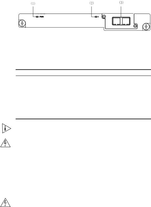
Expansion Module You can use this slot to install an Expansion Module. The Switch 5500G Slot (Switch 5500G-EI Family provides one expansion module slot on the rear panel in which you
Only) can use an 8-port 1000 Mbps SFP module, a 1-port 10 Gbps XENPAK module, or a 2-port 10 Gbps XFP module.
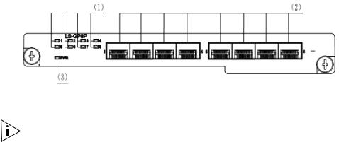
8-port 1000 Mbps SFP module
This module, shown in Figure 12, provides eight 1000 Mbps 1000Base-X
SFP transceiver ports.
Figure 12 8-port 1000 Mbps SFP module
(1) Port status LEDs |
2) SFP ports |
3) Module power LED |
Notes:
■The types of available SFP modules may change over time. Refer to www.3com.com for the latest transceiver support.
■For SFP module specifications, refer to 3Com Web site at www.3com.com
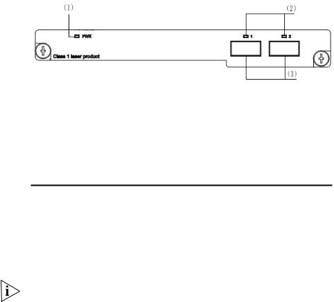
2-port 10 Gbps XFP module
This module, shown in Figure 13, provides two 10 Gbps XFP optical ports.
Switch 5500 — Rear View Detail 23
Figure 13 2-port 10 Gbps XFP module
(1) Module power LED (2) 10 Gbps XFP optical |
(3) 10 Gbps XFP optical ports |
ports |
|
Table 6 lists the available XFP transceivers.
Table 6 XFP transceivers supported by 2-port 10 Gbps XFP module
Type |
Model |
|
|
XFP transceivers |
3CXFP90 10GBASE-LRM |
|
3CXFP92 10GBASE-LR |
|
3CXFP94 10GBASE-SR |
|
3CXFP95 10GBASE-CX4 |
|
3CXFP96 10GBASE-ER |
|
|
Notes: |
|
■The type of 10 Gbps XFP module may be different from those listed above. For the most up-to-date information, refer to www.3com.com.
■For XFP transceiver specifications, refer to 3Com’s Web site at www.3Com.com.
1-port 10 Gbps XENPAK module
This module, shown in Figure 14, provides one 10 Gbps XENPAK transceiver port.
24 CHAPTER 1: INTRODUCING THE SWITCH 5500 FAMILY
Figure 14 1-port 10 Gbps XENPAK module
(1) Module power (2) Port status LED |
(3) 10 Gbps XENPAK |
LED |
optical/electrical port |
The Table 7 lists the available XENPAK optical modules:
Table 7 XENPAK optical port module supported by 1-port 10 Gbps XENPAK module
Table 8 Type |
Table 9 Model |
XENPAKs that are supported 3CXENPAK91 10GBASE-LX4 3CXENPAK92 10GBASE-LR
XENPAK optical module 3CXENPAK93 10GBASE-T 3CXENPAK94 10GBASE-SR 3CXENPAK95 10GBASE-CX4 3CXENPAK96 10GBASE-ER
For specifications of XENPAK Transceivers, refer to 3Com’s Web site at
www.3Com.com.
WARNING: When an Expansion Module is not installed, ensure that the blanking plate is fitted by tightening all screws with a suitable tool. Failure to fit a blanking plate may void the product warranty.
Power Socket The Switch automatically adjusts its power setting to any supply voltage in the range 100-240 VAC.
Open Book Warning Before installing or removing any components from the Switch 5500 Labels Family or carrying out any maintenance procedures, you must read the
safety information provided in Appendix A of this guide.
AVERTISSEMENT: Avant d'installer ou d'enlever tout composant des commutateurs de la gamme Switch 5500 ou d'entamer une procédure
Switch 5500 — Rear View Detail 25
de maintenance, lisez les informations relatives à la sécurité qui se trouvent dans l'annexe A de ce guide.
VORSICHT:Bevor Sie Komponenten der Switch 5500-Baureihe installieren oder deinstallieren und bevor Sie Wartungsarbeiten ausführen, müssen Sie die in Anhang A dieses Handbuchs aufgeführten Sicherheitshinweise lesen.
ADVERTENCIA: Antes de instalar o extraer cualquier componente del Switch 5500 Family o de realizar tareas de mantenimiento, debe leer la información de seguridad facilitada en el Apéndice A de esta guía.

26 CHAPTER 1: INTRODUCING THE SWITCH 5500 FAMILY
Redundant Power
System Socket
Stacking Cable Ports
(Switch 5500G-EI)
AVVERTENZA: Prima di installare o rimuovere qualsiasi componente dello Switch 5500 Family o di eseguire qualsiasi procedura di manutenzione, leggere le informazioni di sicurezza riportate nell'Appendice A di questa guida.
OSTRZEŻENIE: Przed instalacją lub usunięciem jakichkolwiek elementów z przełącznika z rodziny 5500 lub przeprowadzeniem prac konserwacyjnych należy zapoznać się z informacjami o bezpieczeństwie zawartymi w Załączniku A niniejszego podręcznika.
For protection against an internal power supply failure, you can use this socket to connect the Switch to a -48 DC Redundant Power System.
You can use these ports to connect the following cables:
■Stacking Cable (3C17262) — this cable enables you to stack together two switches up to three rack units apart.
■Resilient Stacking Cable (3C17263) — this cable enables you to stack together two switches up to sixteen rack units apart.
You can stack together any combination of 5500G-EI 24 port and 48 port units, up to a maximum of eight units.
For more information on how to connect a stacking cable to your Switch units, refer to the Installation Guide that accompanies your cable.
You canno create a Fabric by interconnecting a 3Com Switch 5500G with any other 3Com device (such as a 5500-EI) or mix Enhanced Image (EI) Switch 5500 units with Standard Image (SI) units.

Default Settings 27
Default Settings Table 10 shows the default settings for the Switch 5500 Family:
Table 10 Default Settings
Feature |
Switch 5500 |
|
|
Automatic IP Configuration |
Enabled |
Port Status |
Enabled |
Port Speed |
Auto-negotiated |
Duplex Mode |
Auto-negotiated |
Power over Ethernet |
Enabled (3CR17171-91 and 3CR17172-91 only) |
Flow Control |
Auto-negotiated |
Broadcast Storm Control |
Enabled |
Virtual LANs (VLANs) |
All ports belong to the untagged Default VLAN |
|
(VLAN 1) with IEEE Std 802.1Q-1998 learning |
|
operational |
Management VLAN |
Fixed as VLAN 1 on 5500-SI units. Can be any |
|
VLAN for 5500-EI/5500G-EI units. |
Link Aggregation Control |
Disabled per port |
Protocol (LACP) |
|
IP Multicast Filtering |
Filtering enabled |
Rapid Spanning Tree Protocol |
Enabled |
Fast Start |
Enabled on front panel ports |
RMON Alarm |
Enabled |
Webcache Support |
Disabled |
Traffic Prioritization |
All ports prioritize NBX VoIP traffic (LAN and IP). |
|
All ports set to “best effort” for all other traffic. |
Port Security |
Disabled per port |
Configuration Save and |
Disabled |
Restore |
|
Spanning Tree Protocol |
Enabled |
Smart Auto-sensing |
Enabled |
|
|
28 CHAPTER 1: INTRODUCING THE SWITCH 5500 FAMILY
2 |
INSTALLING THE SWITCH |
|
This chapter contains the information you need to install and set up the Switch 5500. It covers the following topics:
■Package Contents
■Choosing a Suitable Site
■Rack-mounting
■Connecting a Redundant Power Supply
■Placing Units On Top of Each Other
■The Power-up Sequence
■SFP Operation
■Packing and Shipping the Switch 5500
WARNING: Safety Information. Before installing or removing any components from the Switch 5500 or carrying out any maintenance procedures, you must read the safety information provided in Appendix A of this guide.
AVERTISSEMENT: Consignes de sécurité. Avant d'installer ou d'enlever tout composant du Switch 5500 ou d'entamer une procédure de maintenance, lisez les informations relatives à la sécurité qui se trouvent dans l'Appendice A de ce guide.
VORSICHT: Sicherheitsinformationen. Bevor Sie Komponenten aus dem Switch 5500 entfernen oder dem Switch 5500 hinzufuegen oder Instandhaltungsarbeiten verrichten, lesen Sie die Sicherheitsanweisungen, die in Appendix A (Anhang A) in diesem Handbuch aufgefuehrt sind.
ADVERTENCIA: Información de seguridad. Antes de instalar o extraer cualquier componente del Switch 5500 o de realizar tareas de mantenimiento, debe leer la información de seguridad facilitada en el Apéndice A de esta guía del usuario.

30 CHAPTER 2: INSTALLING THE SWITCH
AVVERTENZA: Informazioni di sicurezza. Prima di installare o rimuovere qualsiasi componente dal Switch 5500 o di eseguire qualsiasi procedura di manutenzione, leggere le informazioni di sicurezza riportate nell'Appendice A della presente guida per l'utente.
OSTRZEŻENIE: Informacje o zabezpieczeniach. Przed instalacją lub usunięciem jakichkolwiek elementów z product lub przeprowadzeniem prac konserwacyjnych należy zapoznać się z informacjami o bezpieczeństwie zawartymi w Załączniku A niniejszego podręcznika.
Package Contents The Switch 5500 packaging contains the following for all units:
■Switch unit
■Release Notes
■RPS -48V DC Connector
■Unit Information Labels
■Warranty Information
■RPS Flyer
■Power Cord
■Console Cable (RJ-45)
■RPS Connector (and backshell)
■RPS Connector Cable Tie
■Earthing Lead
■Mounting brackets
■Screws
■4 x Rubber feet
Table 11 below details the packaging contents specific to each unit in the
Switch 5500 Family.
Loading...