


 Loading...
3Com® Switch 4210 Family
Getting Started
Switch 4210 PWR 9-Port
Switch 4210 PWR 18-Port
Switch 4210 PWR 26-Port
Switch 4210 9-Port
Switch 4210 18-Port
Switch 4210 26-Port
Switch 4210 52-Port
www.3Com.com
Part Number: 10016119 Rev. AB Published: January, 2008
3Com Corporation
350 Campus Drive
Marlborough, MA
USA 01752-3064
Copyright © 2006-2008, 3Com Corporation. All rights reserved. No part of this documentation may be reproduced in any form or by any means or used to make any derivative work (such as translation, transformation, or adaptation) without written permission from 3Com Corporation.
3Com Corporation reserves the right to revise this documentation and to make changes in content from time to time without obligation on the part of 3Com Corporation to provide notification of such revision or change.
3Com Corporation provides this documentation without warranty, term, or condition of any kind, either implied or expressed, including, but not limited to, the implied warranties, terms or conditions of merchantability, satisfactory quality, and fitness for a particular purpose. 3Com may make improvements or changes in the product(s) and/or the program(s) described in this documentation at any time.
If there is any software on removable media described in this documentation, it is furnished under a license agreement included with the product as a separate document, in the hard copy documentation, or on the removable media in a directory file named LICENSE.TXT or !LICENSE.TXT. If you are unable to locate a copy, please contact 3Com and a copy will be provided to you.
UNITED STATES GOVERNMENT LEGEND
If you are a United States government agency, then this documentation and the software described herein are provided to you subject to the following:
All technical data and computer software are commercial in nature and developed solely at private expense. Software is delivered as “Commercial Computer Software” as defined in DFARS 252.227-7014 (June 1995) or as a “commercial item” as defined in FAR 2.101(a) and as such is provided with only such rights as are provided in 3Com’s standard commercial license for the Software. Technical data is provided with limited rights only as provided in DFAR 252.227-7015 (Nov 1995) or FAR 52.227-14 (June 1987), whichever is applicable. You agree not to remove or deface any portion of any legend provided on any licensed program or documentation contained in, or delivered to you in conjunction with, this User Guide.
Unless otherwise indicated, 3Com registered trademarks are registered in the United States and may or may not be registered in other countries.
3Com and the 3Com logo are registered trademarks of 3Com Corporation.
Cisco is a registered trademark of Cisco Systems, Inc.
Funk RADIUS is a registered trademark of Funk Software, Inc.
Aegis is a registered trademark of Aegis Group PLC.
Intel and Pentium are registered trademarks of Intel Corporation. Microsoft, MS-DOS, Windows, and Windows NT are registered trademarks of Microsoft Corporation. Novell and NetWare are registered trademarks of Novell, Inc. UNIX is a registered trademark in the United States and other countries, licensed exclusively through X/Open Company, Ltd.
IEEE and 802 are registered trademarks of the Institute of Electrical and Electronics Engineers, Inc.
All other company and product names may be trademarks of the respective companies with which they are associated.
ENVIRONMENTAL STATEMENT
It is the policy of 3Com Corporation to be environmentally-friendly in all operations. To uphold our policy, we are committed to:
Establishing environmental performance standards that comply with national legislation and regulations.
Conserving energy, materials and natural resources in all operations.
Reducing the waste generated by all operations. Ensuring that all waste conforms to recognized environmental standards. Maximizing the recyclable and reusable content of all products.
Ensuring that all products can be recycled, reused and disposed of safely.
Ensuring that all products are labelled according to recognized environmental standards.
Improving our environmental record on a continual basis.
End of Life Statement
3Com processes allow for the recovery, reclamation and safe disposal of all end-of-life electronic components.
Regulated Materials Statement
3Com products do not contain any hazardous or ozone-depleting material.
CONTENTS
ABOUT THIS GUIDE
|
Download the Latest Software and Documentation for Your 3Com Switch 5 |
||||||
|
Before You Start 5 |
|
|
|
|
|
|
|
Related Documentation |
6 |
|
|
|
|
|
1 |
PRODUCT INTRODUCTION |
|
|
|
|
||
|
Overview 7 |
|
|
|
|
|
|
|
Introduction to the Switch 4210 Family PWR Switches 8 |
||||||
|
Introduction to the Switch 4210 Family Non-PWR Models 14 |
||||||
|
Technical Specifications |
19 |
|
|
|
|
|
|
SFP Modules Supported for the Switch 4210 21 |
|
|||||
2 INSTALLING THE SWITCH |
|
|
|
|
|
||
|
Rack-Mounting the Switch |
24 |
|
|
|
||
|
Mounting the Switch on a Desktop |
27 |
|
|
|||
|
The Power-up Sequence |
27 |
|
|
|
|
|
|
Connecting a Redundant Power Supply |
28 |
|
||||
|
Connecting the Console Cable |
32 |
|
|
|
||
3 MANAGING YOUR SWITCH |
|
|
|
||||
|
Methods of Managing a Switch |
36 |
|
|
|||
|
Setting Up Your Switch |
37 |
|
|
|
|
|
|
Viewing Automatically Configured IP Information |
40 |
|||||
|
Manually Configuring IP Information |
42 |
|
|
|||
|
Setting Up Command Line Interface Management |
47 |
|||||
|
Setting Up Command Line Interface Management using SSH 48 |
||||||
|
Setting Up Web Interface Management |
48 |
|
||||
|
Setting Up SNMP Management |
49 |
|
|
|||
|
Default Users and Passwords |
|
50 |
|
|
|
|
4 |
PROBLEM SOLVING |
|
|
|
|
|
|
|
Solving Problems Indicated by LEDs |
52 |
|
|
|||
|
Solving Hardware Problems |
53 |
|
|
|
||
|
Solving Communication Problems |
54 |
|
|
|||
|
Solving Fabric Formation Problems |
55 |
|
|
|||
A |
PIN-OUTS |
|
|
|
|
|
|
|
Null Modem Cable |
57 |
|
|
|
|
|
|
PC-AT Serial Cable |
57 |
|
|
|
|
|
|
Modem Cable |
58 |
|
|
|
|
|
|
Ethernet Port RJ-45 Pin Assignments |
58 |
|||||
B |
OBTAINING SUPPORT FOR YOUR 3COM PRODUCTS |
||||||
|
Register Your Product to Gain Service Benefits 59 |
||||||
|
Solve Problems Online |
59 |
|
|
|
||
|
Purchase Extended Warranty and Professional Services 59 |
||||||
|
Access Software Downloads |
59 |
|
|
|||
|
Contact Us |
60 |
|
|
|
|
|
C |
3COM NETWORK MANAGEMENT |
||||||
|
3Com Network Supervisor |
63 |
|
|
|||
|
3Com Network Director |
63 |
|
|
|||
|
3Com Network Access Manager |
64 |
|
||||
|
3Com Enterprise Management Suite |
65 |
|||||
|
Integration Kit with HP OpenView Network Node Manager 65 |
||||||
D |
REDUNDANT POWER SUPPLY SAFETY INFORMATION |
||||||
|
Important Safety Information |
67 |
|
|
|||
|
L’information de Sécurité Importante |
68 |
|||||
|
Wichtige Sicherheitsinformationen |
68 |
|||||
|
Información de Seguridad Importante |
69 |
|||||
|
Importanti Informazioni di Sicurezza |
71 |
|||||
|
Wa¿ne informacje o zabezpieczeniach |
71 |
|||||
|
Regulatory Notices |
73 |
|
|
|
|
|

ABOUT THIS GUIDE
Download the Latest |
Thank you for purchasing a 3Com Switch 4210. As part of our commitment to |
Software and |
bringing you the most capable and dependable network equipment, 3Com offers |
Documentation for |
free software maintenance updates and documentation updates on our website. |
Your 3Com Switch |
To obtain the most up-to-date operating software and user documentation for the |
|
|
|
Switch 4210, point your web browser to: www.3Com.com/4210 and select the |
|
“Support and Registration” link. |
|
You must register your 3Com switch before receiving software upgrades. To |
|
register, point your web browser to eSupport.3Com.com. |
|
|
Before You Start |
The guide is intended for use by network administrators who install and set up |
|
network equipment; consequently, it assumes a basic working knowledge of LANs |
|
(Local Area Networks). |
Release Notes |
The Release Notes provide important information about the current software |
|
release, including new features, modifications, and known problems. You should |
|
read the Release Notes before installing the switch in your network. |
|
If the information in the Release Notes differs from this guide, follow the |
|
instructions in the Release Notes. |
|
User guides and release notes are available in Adobe Acrobat Reader Portable |
|
Document Format (PDF) on the 3Com World Wide Web site at |
|
http://www.3com.com |
Conventions Table 1 lists important conventions that are used throughout this guide.
Table 1 |
Notice Icons |
|
|
|
|
Icon |
Notice Type |
Description |
|
|
|
|
Information note |
Information that describes important features or |
|
|
instructions |
|
Caution |
Information that alerts you to potential loss of data or |
|
|
potential damage to an application, system, or device |
|
Warning |
Information that alerts you to potential personal injury |
|
|
|

6 ● |
3Com Switch 4210 Family |
|
Command Reference |
Related
Documentation
In addition to this guide, the Switch 4210 documentation set includes the following:
■3Com Switch 4210 Family Configuration Guide
This guide contains information on the features supported by your switch and how they can be used to optimize your network. It is supplied in PDF format on the 3Com Web site.
■3Com Switch 4210 Family Command Reference Guide
This guide provides detailed information about the web interface and command line interface that enable you to manage the switch. It is supplied in PDF format on the 3Com Web site.
■Release Notes
These notes provide information about the current software release, including new features, modifications, and known problems. The release notes are supplied in hard copy with your switch.
PRODUCT INTRODUCTION
1
Overview |
The 3Com Switch 4210 Family provides high-performance, high-density, |
|
easy-to-install, NMS-manageable intelligent Ethernet switches that support |
|
wire-speed Layer 2 switching. |
|
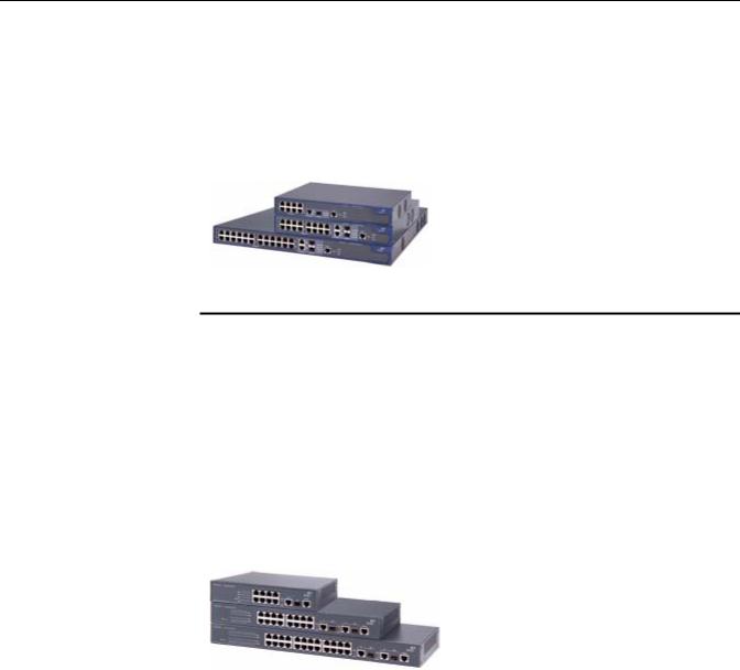
Three of the Switch 4210 Family models support industry standard IEEE 802.3af |
|
Power over Ethernet (PoE). Figure 1 displays these models and Table 1 provides a |
|
description of their features. |
|
Figure 1 Power over Ethernet models |
Table 1 Power over Ethernet models
|
|
Number of |
Number of 1000 |
Number of |
|
|
10/100 Mbps |
Mbps uplink |
Console |
Model |
Power supply |
ports |
ports |
ports |
|
|
|
|
|
Switch 4210 PWR |
AC input |
8 |
One Combo port |
1 |
9-port |
|
|
|
|
Switch 4210 PWR |
AC input |
16 |
Two Combo ports |
1 |
18-port |
|
|
|
|
Switch 4210 PWR |
AC or RPS DC |
24 |
|
1 (on rear) |
26-port |
input |
|
|
|
|
|
|
|
|
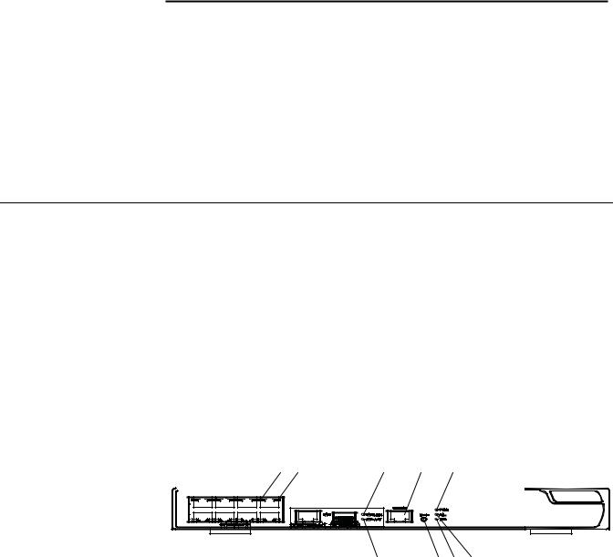
Three of the Switch 4210 Family models are available for simple connectivity without PoE. Figure 2 displays these models and Table 2 describes its features.
Figure 2 Non Power over Ethernet models
8 CHAPTER 1: PRODUCT INTRODUCTION
Table 2 Non Power over Ethernet models
|
|
Number of |
|
Number of |
|
|
10/100 Mbps |
Number of 1000 Mbps |
Console |
Model |
Power supply |
ports |
uplink ports |
ports |
|
|
|
|
|
Switch 4210 |
AC input |
8 |
One Combo port |
1 |
9-port |
|
|
|
|
Switch 4210 |
AC input |
16 |
Two Combo ports |
1 |
18-port |
|
|
|
|
Switch 4210 |
AC input |
24 |
Two Combo ports |
1 |
26-port |
|
|
|
|
Switch 4210 |
AC input |
48 |
Two 10/100/100 ports |
1 |
52-port (not |
|
|
|
|
shown) |
Two SFP ports |
|
|
|
|
Introduction to the
Switch 4210 Family
PWR Switches
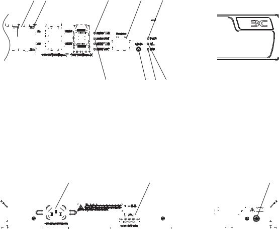
Switch 4210 9-port PWR Front panel
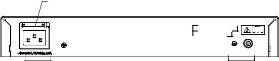
Each Switch 4210 9-port PWR unit provides eight 10/100Base-TX autosensing Ethernet ports, one 10/100/1000Base-T Ethernet port, one 100/1000Base SFP ports, and one Console port. The SFP port and the 10/100/1000BASE-T Ethernet port form a Combo port. You can use either the SFP port or the 10/100/1000BASE-T Ethernet port at one time.
Figure 3 shows the front panel of a Switch 4210 9-port PWR.
Figure 3 Front panel of a Switch 4210 9-port PWR
|
|
|
|
|
|
|
|
|
|
(1) |
(2) |
(3) |
(4) |
|
|
|
|
|||||
|
|
|
|
|
|
|
|
|
|
|
|
|
|
|
|
|
|
|
|
|
|
|
|
|
|
|
|
|
|
|
|
|
|
|
|
|
|
|
|
|
|
|
|
|
|
1 |
4 |
5 |
8 |
|
(8) |
(7) (6) (5) |
|||
(1) |
10/100Base-TX autosensing Ethernet port status LED |
|
|
|
|
(2) |
Link LED for Combo port |
(3) |
Console port |
||
(4) |
Power LED (PWR) |
(5) A/L LED |
|||
(6) |
D/S LED |
(7) |
Mode button |
||
(8) |
Active LED for Combo port |
|
|
|
|
Introduction to the Switch 4210 Family PWR Switches |
9 |
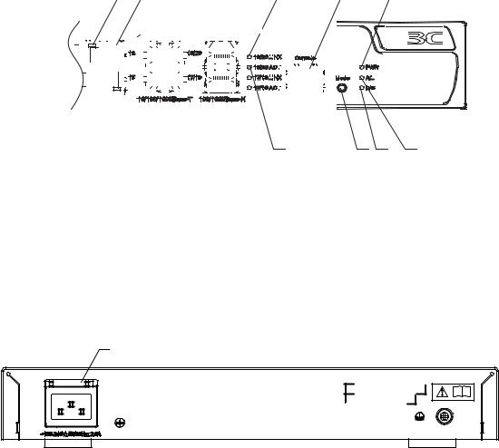
Rear panel
Figure 4 The Switch 4210 9-port PWR model’s rear panel
(1)
|
(1) AC power socket |
( |
|
Side panel |
|
|
Each Switch 4210 9-port PWR provides a security slot through which you can lock |
|
|
the device together with an irremovable object to prevent theft. The security slot is |
|
|
located on the left side panel, as shown in Figure 7. |
|
n |
If the left screw hole above the security slot is used, the security slot cannot be |
|
|
used. |
|
Switch 4210 PWR
18-port
Power system
Switch 4210 PWR 9-port units are able to power attached devices using standard 802.3af Power over Ethernet. The total available power for PoE on this model is 70W, enough to power four ports at full 15.4W required of the PoE standard. Each Switch 4210 9-port PWR unit supports AC input.
■Rated Voltage Range: 100 VAC to 240 VAC, 50 Hz/60 Hz
■Input voltage range: 90 VAC to 264 VAC, 47 HZ to 63 Hz
Cooling system
The Switch 4210 9-port PWR units each run two fans for heat dissipation.
Front panel
Switch 4210s 18-port PWR each provide sixteen 10/100Base-TX autosensing Ethernet ports, two 10/100/1000Base-T Ethernet ports, two 100/1000Base SFP ports, and one Console port. Each SFP port and the corresponding 10/100/1000BASE-T Ethernet port form a Combo port. For each Combo port, either the SFP port or the corresponding 10/100/1000BASE-T Ethernet port can be used at a time.
Figure 5 shows the front panel of a Switch 4210 18-port PWR.
10 CHAPTER 1: PRODUCT INTRODUCTION
Figure 5 Front panel of a Switch 4210 18-port PWR
|
|
|
|
|
|
|
|
|
|
|
|
(1) |
|
|
|
|
|
|
|
|
|
|
|
|
|
|
|
|
|
|
|
|
|
|
|
|
|
|
|
|
(2) |
|
|
|
|
|
|
|
|
|
|
|
|
(3) |
|
|
|
|
|
|
(4) |
|
|
|
|
|||||||||||||
|
|
|
|
|
|
|
|
|
|
|
|
|
|
|
|
|
|
|
|
|
|
|
|
|
|
|
|
|
|
|
|
|
|
|
|
|
|
|
|
|
|
|
|
|
|
|
|
|
|
|
|
|
|
|
|
|
|
|
|
|
|
|
|
|
|
|
|
|
|
|
|
|
|
|
|
|
|
|
|
|
|
|
|
|
|
|
|
|
|
|
|
|
|
|
|
|
|
|
|
|
|
|
|
|
|
|
|
|
|
|
|
|
|
|
|
|
|
|
|
|
|
|
|
|
|
|
|
|
|
|
|
|
|
|
|
|
|
|
|
|
|
|
|
|
|
|
|
|
|
|
|
|
|
|
|
|
|
|
|
|
|
|
|
|
|
|
|
|
|
|
|
|
|
|
|
|
|
|
|
|
|
|
|
|
|
|
|
|
|
|
|
|
|
|
|
|
|
|
|
|
|
|
|
|
|
|
|
|
|
|
|
|
|
|
|
|
|
|
|
|
|
|
|
|
|
|
|
|
|
|
|
|
|
|
|
|
|
|
|
|
|
|
|
|
|
|
|
|
|
|
|
|
|
|
|
|
|
|
|
|
|
|
|
|
|
|
|
|
|
|
|
|
|
|
|
|
|
|
|
|
|
|
|
|
|
|
|
|
|
|
|
|
|
|
|
|
|
|
|
|
|
|
|
|
|
|
|
|
|
|
|
|
|
|
|
|
|
|
|
|
|
|
|
|
|
|
|
|
|
|
|
|
|
|
|
|
|
|
|
|
|
|
|
|
|
|
|
|
|
|
|
|
|
|
|
|
|
|
|
|
|
|
|
|
|
|
|
|
|
|
|
|
|
|
|
|
|
|
|
|
|
|
|
|
|
|
|
|
|
|
|
|
|
|
|
|
|
|
|
|
|
|
|
|
|
|
|
|
|
|
|
|
|
|
|
|
|
|
|
|
|
|
|
|
|
|
|
|
|
|
|
|
|
|
|
|
|
|
|
|
|
|
|
|
|
|
|
|
|
|
|
|
|
|
|
|
|
|
|
|
|
|
|
|
|
|
|
|
|
|
|
|
|
|
|
|
|
|
|
|
|
|
|
|
|
|
|
|
|
|
|
|
|
|
|
|
|
|
|
|
|
|
|
|
|
|
|
|
|
|
|
|
|
|
|
|
|
|
|
|
|
|
|
|
|
|
|
|
|
|
|
|
|
|
|
|
|
|
|
|
|
|
|
|
|
|
|
|
|
|
|
|
|
|
|
|
|
|
|
|
|
|
|
|
|
|
|
|
|
|
|
|
|
|
|
|
|
|
|
|
|
|
|
|
|
|
|
|
|
|
|
|
|
|
|
|
|
|
|
|
|
|
|
|
|
|
|
|
|
|
|
|
|
|
|
|
|
|
|
|
|
|
|
|
|
|
|
|
|
|
|
|
|
|
|
|
|
|
|
|
|
|
|
|
|
|
|
|
|
|
|
|
|
|
|
|
|
|
|
|
|
|
|
|
|
|
|
|
|
|
|
|
|
|
|
|
|
|
|
|
|
|
|
|
|
|
|
|
|
|
|
|
|
|
|
|
|
|
|
|
|
|
|
|
|
|
|
|
|
|
(8) (7) (6) (5)
(1) |
10/100Base-TX autosensing Ethernet port status LED |
|
|
(2) |
Link LED for Combo port |
(3) |
Console port |
(4) |
Power LED (PWR) |
(5) A/L LED |
|
(6) |
D/S LED |
(7) |
Mode button |
(8) |
Active LED for Combo port |
|
|
Rear panel
Figure 6 Rear panel of a Switch 4210 18-port PWR
(1)
(1) AC power socket
Side panel
Each Switch 4210 18-port PWR provides a security slot, through which you can lock the device together with an irremovable object to prevent theft. The security slot is located on the left side panel, as shown in Figure 7.
Introduction to the Switch 4210 Family PWR Switches 11
Figure 7 Security slot on left side panel of a Switch 4210 18-port PWR
(1) |
(1): Security slot
n |
If the left screw hole above the security slot is used, the security slot cannot be |
|
used. |
Switch 4210 PWR
26-port
Power system
Switch 4210 18-port PWR units support AC input.
■Rated Voltage Range: 100 VAC to 240 VAC, 50 Hz/60 Hz
■Input voltage range: 90 VAC to 264 VAC, 47 Hz to 63 Hz
Switch 4210 PWR 18-Port units are able to power attached devices using standard 802.3af Power over Ethernet. The total available power for PoE on this model is 135W; enough to power 8-Ports at full 15.4W required of the PoE standard.
Cooling system
Switch 4210s 18-port PWR each run two fans for heat dissipation.
Front panel
The Switch 4210 26-port PWR model provides 24 10/100Base-TX autosensing Ethernet ports, two 10/100/1000Base-T Ethernet ports, two 100/1000Base SFP ports, and one Console port. Each SFP port and the corresponding 10/100/1000BASE-T Ethernet port form a Combo port. For each Combo port, you can use either the SFP port or the corresponding 10/100/1000BASE-T Ethernet port at one time.
Figure 8 shows the front panel of the Switch 4210 26-port PWR model.
12 CHAPTER 1: PRODUCT INTRODUCTION
Figure 8 The Switch 4210 26-port PWR model’s front panel
|
|
|
|
|
|
|
|
|
|
|
|
|
|
|
(1) |
|
|
|
|
|
|
|
|
|
|
|
|
(2) |
|
|
|
|
|
|
|
|
|
|
(3) |
|
|
|
|
(4) |
|
|
|
|
|
|
|
|
|
|
|||||||||
|
|
|
|
|
|
|
|
|
|
|
|
|
|
|
|
|
|
|
|
|
|
|
|
|
|
|
|
|
|
|
|
|
|
|
|
|
|
|
|
|
|
|
|
|
|
|
|
|
|
|
|
|
|
|
|
|
|
|
|
|
|
|
|
|
|
|
|
|
|
|
|
|
|
|
|
|
|
|
|
|
|
|
|
|
|
|
|
|
|
|
|
|
|
|
|
|
|
|
|
|
|
|
|
|
|
|
|
|
|
|
|
|
|
|
|
|
|
|
|
|
|
|
|
|
|
|
|
|
|
|
|
|
|
|
|
|
|
|
|
|
|
|
|
|
|
|
|
|
|
|
|
|
|
|
|
|
|
|
|
|
|
|
|
|
|
|
|
|
|
|
|
|
|
|
|
|
|
|
|
|
|
|
|
|
|
|
|
|
|
|
|
|
|
|
|
|
|
|
|
|
|
|
|
|
|
|
|
|
|
|
|
|
|
|
|
|
|
|
|
|
|
|
|
|
|
|
|
|
|
|
|
|
|
|
|
|
|
|
|
|
|
|
|
|
|
|
|
|
|
|
|
|
|
|
|
|
|
|
|
|
|
|
|
|
|
|
|
|
|
|
|
|
|
|
|
|
|
|
|
|
|
|
|
|
|
|
|
|
|
|
|
|
|
|
|
|
|
|
|
|
|
|
|
|
|
|
|
|
|
|
|
|
|
|
|
|
|
|
|
|
|
|
|
|
|
|
|
|
|
|
|
|
|
|
|
|
|
|
|
|
|
|
|
|
|
|
|
|
|
|
|
|
|
|
|
|
|
|
|
|
|
|
|
|
|
|
|
|
|
|
|
|
|
|
|
|
|
|
|
|
|
|
|
|
|
|
|
|
|
|
|
|
|
|
|
|
|
|
|
|
|
|
|
|
|
|
|
|
|
|
|
|
|
|
|
|
|
|
|
|
|
|
|
|
|
|
|
|
|
|
|
|
|
|
|
|
|
|
|
|
|
|
|
|
|
|
|
|
(8) |
(7) (6) (5) |
|
(1) |
10/100Base-TX autosensing Ethernet port status LED |
||
(2) |
Link LED for Combo port |
(3) |
Console port |
(4) |
Power LED (PWR) |
(5) A/L LED |
|
(6) |
D/S LED |
(7) |
Mode button |
(8) |
Active LED for Combo port |
|
|
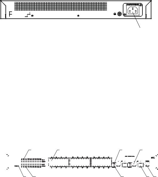
Rear panel
Figure 9 Rear panel of a Switch 4210 26-port PWR
|
|
|
|
|
|
|
|
|
|
|
|
|
|
|
|
|
(1) |
|
|
|
|
|
|
|
|
|
|
|
|
|
|
|
|
|
|
|
|
|
|
|
|
|
|
|
|
|
|
|
|
|
(2) |
|
|
|
(3) |
||||||||||||||||||||||
|
|
|
|
|
|
|
|
|
|
|
|
|
|
|
|
|
|
|
|
|
|
|
|
|
|
|
|
|
|
|
|
|
|
|
|
|
|
|
|
|
|
|
|
|
|
|
|
|
|
|
|
|
|
|
|
|
|
|
|
|
|
|
|
|
|
|
|
|
|
|
|
|
|
|
|
|
|
|
|
|
|
|
|
|
|
|
|
|
|
|
|
|
|
|
|
|
|
|
|
|
|
|
|
|
|
|
|
|
|
|
|
|
|
|
|
|
|
|
|
|
|
|
|
|
|
|
|
|
|
|
|
|
|
|
|
|
|
|
|
|
|
|
|
|
|
|
|
|
|
|
|
|
|
|
|
|
|
|
|
|
|
|
|
|
|
|
|
|
|
|
|
|
|
|
|
|
|
|
|
|
|
|
|
|
|
|
|
|
|
|
|
|
|
|
|
|
|
|
|
|
|
|
|
|
|
|
|
|
|
|
|
|
|
|
|
|
|
|
|
|
|
|
|
|
|
|
|
|
|
|
|
|
|
|
|
|
|
|
|
|
|
|
|
|
|
|
|
|
|
|
|
|
|
|
|
|
|
|
|
|
|
|
|
|
|
|
|
|
|
|
|
|
|
|
|
|
|
|
|
|
|
|
|
|
|
|
|
|
|
|
|
|
|
|
|
|
|
|
|
|
|
|
|
|
|
|
|
|
|
|
|
|
|
|
|
|
|
|
|
|
|
|
|
|
|
|
|
|
|
|
|
|
|
|
|
|
|
|
|
|
|
|
|
|
|
|
|
|
|
|
|
|
|
|
|
|
|
|
|
|
|
|
|
|
|
|
|
|
|
|
|
|
|
|
|
|
|
|
|
|
|
|
|
|
|
|
|
|
|
(1) AC power socket |
(2) DC power socket |
(3) Grounding screw
|
Power system |
|
Switch 4210 26-port PWR units support AC input or DC input. |
|
■ AC input |
|
■ Rated voltage range: 100 VAC to 240 VAC, 50 Hz/60 Hz |
|
■ Input voltage range: 90 VAC to 264 VAC, 47 Hz to 63 Hz |
|
■ DC input—Rated voltage range: -52 VDC to -56 VDC |
n |
Switch 4210 PWR 26-Port units are able to power attached devices using standard |
|
802.3af Power over Ethernet. The total available power for PoE on this model is |
|
370W; enough to power 24-Ports at full 15.4W required of the PoE standard. |
|
3Com recommends a Redundant Power System (RPS) from Eaton Powerware for |
|
providing DC power to the Switch 4210 PWR 26-Port. For full details, refer to |
|
www.3com.com/rps. |
Cooling system
Switch 4210 26-port PWR units each run four fans for heat dissipation.

Introduction to the Switch 4210 Family PWR Switches 13
The Switch 4210 PWR |
Power LED |
Front Panel LEDs |
Table 3 describes the power LED on the Switch 4210 PWR model. |
|
|
|
Table 3 The power LED on the Switch 4210 PWR models |
LED |
Mark on the panel |
Status |
Description |
|
|
|
|
Power LED |
PWR |
ON |
The switch is powered on. |
|
|
OFF |
The switch is powered off. |
|
|
|
|
10/100BASE-TX Autosensing Ethernet Port Status LED
There are two port status LEDs on both sides (yellow LED on the left and green LED on the right) of the 10/100BASE-TX Ethernet port on the Switch 4210 PWR models. They indicate the port’s active, link, duplex, and speed status.
In addition, there is an A/L LED and a D/S LED on each Switch 4210 PWR model. These two LEDs indicate the port status LEDs mode. When the A/L LED is on, the port status LEDs respectively indicate the port’s active status and link status. When the D/S LED is on, the port status LEDs respectively indicate the port’s duplex status and speed status. Either the A/L LED or the D/S LED is on at one time. For details, see Table 4.
Table 4 Port status LEDs on the Switch 4210 PWR models
Port status |
|
|
|
mode LED |
Port status LED |
Description |
|
|
|
|
|
The A/L LED is |
Yellow LED |
BLINKING |
The port is in the active state and there is |
on |
(left) |
|
traffic on the port. |
|
|
OFF |
The port is in the active state but there is no |
|
|
|
traffic on the port. |
|
Green LED |
ON |
The port is connected properly. |
|
(right) |
OFF |
The port is not connected or is incorrectly |
|
|
||
|
|
|
connected. |
The D/S LED is |
Yellow LED |
ON |
The port operates in the full duplex mode. |
on |
(left) |
OFF |
The port operates in the half duplex mode. |
|
|
||
|
Green LED |
ON |
The port rate is 100 Mbps. |
|
(right) |
OFF |
The port rate is 10 Mbps. |
|
|
||
|
|
|
|
You can change the mode of the port status LEDs by pressing the Mode button. After a switch is powered on, the A/L LED is on initially. If you press the Mode button, the D/S LED will be on. After that, if you press the Mode button again within 45 seconds, the A/L LED will be on again. Otherwise, the A/L LED will automatically be on 45 seconds later.
1000 Mbps Uplink Port Status LED
Table 5 describes the 1000 Mbps upline port status LED on the Switch 4210.
Table 5 The 1000 Mbps uplink port status LED on 4210 PWR models
|
Mark on the |
|
|
LED |
panel |
Status |
Description |
|
|
|
|
1000 Mbps uplink port |
LINK |
ON |
The port is connected properly. |
link LED |
|
OFF |
The port is not connected or is |
|
|
||
|
|
|
incorrectly connected. |
14 CHAPTER 1: PRODUCT INTRODUCTION
Table 5 The 1000 Mbps uplink port status LED on 4210 PWR models
|
Mark on the |
|
|
LED |
panel |
Status |
Description |
1000 Mbps uplink port ACT active LED
BLINKING |
The port is in the active state and |
|
there is traffic on the port. |
OFF |
The port is in the active state but |
|
there is no traffic on the port. |
Introduction to the Switch 4210 Family Non-PWR Models
This section describes each Switch 4210 Family model.
Switch 4210 9-port Front panel
The Switch 4210 9-port model provides eight 10/100Base-TX autosensing Ethernet ports, one 10/100/1000Base-T autosensing Ethernet port, one 100/1000Base-X SFP port, and one Console port. The SFP port and the 10/100/1000BASE-T autosensing Ethernet port form a Combo port. For the Combo port, either the SFP port or the 10/100/1000BASE-T Ethernet port can be used at a time.
Figure 10 shows the front panel of the Switch 4210 9-port model.
Figure 10 The Switch 4210 9-port model’s front panel
(1) |
(2) |
(3) (4) |
|
(8) (7) |
|
(7) |
(6) |
(5) |
(1) |
10/100Base-TX autosensing port Speed LED (green) |
|
|
|
|
(2) |
10/100Base-TX autosensing port |
(3) Combo port Speed LED (green) |
|||
(4) |
10/100/1000Base-T autosensing port |
(5) |
Console port |
|
|
(6) |
100/1000Base-X SFP port |
(7) |
Link/Act LED (green) |
|
|
(8) |
Power LED (PWR) |
|
|
|
|
.

Introduction to the Switch 4210 Family Non-PWR Models 15
Rear panel
Figure 11 The Switch 4210 9-port model’s rear panel
AC input terminal block
Power system
The Switch 4210 9-port model supports AC input.
■Rated Voltage Range: 100 VAC to 240 VAC, 50 Hz/60 Hz
■Input voltage range: 90 VAC to 264 VAC, 47 Hz to 63 Hz
Cooling system
The Switch 4210 cools off naturally.
Switch 4210 18-port Front panel
The Switch 4210 18-port models provide 16 10/100Base-TX autosensing Ethernet ports, two 10/100/1000Base-T autosensing Ethernet ports, two 100/1000Base-X SFP ports, and one Console port. Each SFP port and the corresponding 10/100/1000BASE-T autosensing Ethernet port form a Combo port. For each Combo port, you can use either the SFP port or the corresponding 10/100/1000BASE-T Ethernet port at one time.
Figure 12 shows the Switch 4210 18-port model’s front panel.
Figure 12 The Switch 4210 18-port model’s front panel
(1) |
(2) |
(3) |
(4) |
(8) |
(7) |
(7) |
(6) |
(5) |
(1) |
10/100Base-TX autosensing port Speed LED (green) |
||
(2) |
10/100Base-TX autosensing port |
(3) |
Combo port Speed LED (green) |
(4) |
10/100/1000Base-T autosensing port |
(5) |
Console port |
(6) |
100/1000Base-X SFP port |
(7) |
Link/Act LED (green) |
(8) |
Power LED (PWR) |
|
|
16 CHAPTER 1: PRODUCT INTRODUCTION
Rear panel
Figure 13 The Switch 4210 18-port model’s rear panel
AC input terminal block
Power system
The Switch 4210 18-port model’s support AC input.
■Rated Voltage Range: 100 VAC to 240 VAC, 50 Hz/60 Hz
■Input voltage range: 90 VAC to 264 VAC, 47 Hz to 63 Hz
Cooling system
3Com Switch 4210 non-PWR models cool naturallly through airflow.
Switch 4210 26-port Front panel
The Switch 4210 26-port front panel provides 24 10/100Base-TX autosensing Ethernet ports, two 10/100/1000Base-T autosensing Ethernet ports, two 100/1000Base-X SFP ports, and one Console port. Each SFP port and the corresponding 10/100/1000BASE-T autosensing Ethernet port form a Combo port. For each Combo port, you can use either the SFP port or the corresponding 10/100/1000BASE-T Ethernet port at one time.
Figure 14 shows the front panel of the Switch 4210 26-port model.
Figure 14 The Switch 4210 26-port front panel
|
|
|
(1) |
|
|
|
|
|
|
|
|
|
(2) |
|
|
|
|
|
|
|
|
|
|
|
|
|
|
|
|
|
|
|
|
|
|
|
|
|
|
|
|
|
|
|
|
|
|
|
|
|
|
|
|
|
|
|
|
|
|
|
|
|
|
|
|
|
|
|
|
|
(3) |
(4) |
|
|
|
|
|
|
|
|
|
|
|
|||||||||||||||||||||||||||||||||||||||||||||||
|
|
|
|
|
|
|
|
|
|
|
|
|
|
|
|
|
|
|
|
|
|
|
|
|
|
|
|
|
|
|
|
|
|
|
|
|
|
|
|
|
|
|
|
|
|
|
|
|
|
|
|
|
|
|
|
|
|
|
|
|
|
|
|
|
|
|
|
|
|
|
|
|
|
|
|
|
|
|
|
|
|
|
|
|
|
|
|
|
|
|
|
|
|
|
|
|
|
|
|
|
|
|
|
|
|
|
|
|
|
|
|
|
|
|
|
|
|
|
|
|
|
|
|
|
|
|
|
|
|
|
|
(8) |
(7) |
|
(7) |
(6) |
(5) |
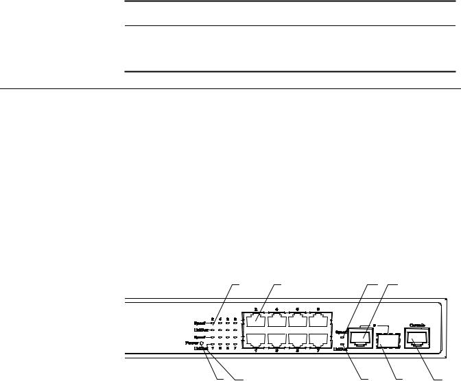
(1) |
10/100Base-TX autosensing port Speed LED (green) |
|
|
|
|
|
(2) |
10/100Base-TX autosensing port |
(3) Combo port Speed LED (green) |
|
|||
(4) |
10/100/1000Base-T autosensing port |
(5) |
Console port |
|
|
|
(6) |
100/1000Base-X SFP port |
(7) |
Link/Act LED (green) |
|
|
|
(8) |
Power LED (PWR) |
|
|
|
|
|
Introduction to the Switch 4210 Family Non-PWR Models 17
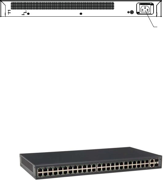
Rear panel
Figure 15 The Switch 4210 26-port rear panel
(2) |
(2) AC input terminal block
Power system
The Switch 4210 26-port model supports AC input.
■Rated Voltage Range: 100 VAC to 240 VAC, 50 Hz/60 Hz
■Input voltage range: 90 VAC to 264 VAC, 47 Hz to 63 Hz
Cooling system
3Com Switch 4210 non-PWR models cool naturally through airflow.
Switch 4210 52-port Front Panel
The Switch 4210 52-port front panel provides 48 10/100Base-TX autosensing Ethernet ports, two 10/100/1000Base-T autosensing Ethernet ports, two 100/1000Base-X SFP ports (The 4 gigabit ports are all active), and one Console port. Each SFP port and the corresponding 10/100/1000BASE-T autosensing Ethernet port form a Combo port. For each Combo port, you can use either the SFP port or the corresponding 10/100/1000BASE-T Ethernet port at one time. The Switch 4210 52-port unit is displayed in Figure 16.
Figure 16 Switch 4210 52-port unit
Power system
The Switch 4210 52-port model supports AC input.
■Rated Voltage Range: 100 VAC to 240 VAC, 50 Hz/60 Hz
■Input voltage range: 90 VAC to 264 VAC, 47 Hz to 63 Hz
Cooling system
3Com Switch 4210 non-PWR models cool naturally through airflow.

18 CHAPTER 1: PRODUCT INTRODUCTION
Switch 4210 Family |
Power LED |
Front Panel LEDs |
Table 6 describes the power LED on the Switch 4210. |
|
|
|
Table 6 The power LED on the Switch 4210 |
LED |
Mark on the panel |
Status |
Description |
|
|
|
|
Power LED |
Power |
ON |
The switch is powered on. |
|
|
OFF |
The switch is powered off. |
|
|
|
|
Port LED
Table 7 describes the 10/100Base-TX autosensing port’s Link/Act LED.
Table 7 The Link/Act LED on the 3Com Switch 4210
LED |
Status |
Description |
|
|
|
Link/Act LED (green) |
ON |
The port is connected properly. |
|
BLINKING |
The port is in the active state and there is |
|
|
traffic on the port. |
|
OFF |
The port is not connected or is incorrectly |
|
|
connected. |
|
|
|
Table 8 describes the Speed LED on the 10/100Base-TX port.
Table 8 The 10/100Base-TX port Speed LED on the Switch 4210
LED |
Status |
Description |
|
|
|
10/100Base-TX autosensing |
ON |
The port is operating at 100 Mbps. |
port Speed LED (green) |
OFF |
The port is operating at 10 Mbps. |
|
||
|
|
|
For a description of the Link/Act LED of the Combo port, see Table 7. When the port is connected correctly, the Speed LED indicates the operating speeds of the Combo port, as shown in Table 9.
Table 9 The Combo port Speed LED on the Switch 4210
LED |
Operating port |
|
Status |
Description |
|
|
|
|
|
Combo port |
100/1000Base-X |
Connected |
ON |
The port is operating at |
Speed LED |
SFP port |
to a 1000 |
|
1000 Mbps. |
(green) |
|
Mbps optical |
|
|
|
|
module |
|
|
|
|
Connected |
OFF |
The port is operating at |
|
|
to a 100 |
|
100 Mbps. |
|
|
Mbps optical |
|
|
|
|
module |
|
|
|
10/100/1000Base-T autosensing |
ON |
The port is operating at |
|
|
port |
|
|
1000 Mbps. |
|
|
|
OFF |
The port is operating at |
|
|
|
|
10/100 Mbps. |
|
|
|
|
|

Technical Specifications |
19 |
Technical
Specifications
Table 10 Technical specifications for the Switch 4210
Model |
Switch 4210 52-port |
Switch 4210 26-port |
Switch 4210 18-port |
Switch 4210 9-port |
|
|
|
|
|
Physical dimensions (H |
43.6 x 440 x 225 mm |
43.6 × 440 × 160 mm |
43.6 × 360 × 160 mm |
43.6 × 230 × 160 mm |
× W × D) |
(1.7 x 17.3 x 8.8 in.) |
(1.7 × 17.3 × 6.3 in.) |
(1.7 × 14.2 × 6.3 in.) |
(1.7 × 9.1 × 6.3 in.) |
|
|
|
|
|
|
|
|
|
|
Weight |
12.1 lbs (5.5 Kgs) |
4.7 lbs (2.14 Kgs) |
3.4 lbs (1.53 kg.) |
2.3 lbs (1.06 kg.) |
|
|
|
|
|
Number of fixed ports |
48 x 10/100Base-TX |
24 × 10/100Base-TX |
16 × 10/100Base-TX |
8 × 10/100Base-TX |
|
autosensing Ethernet |
autosensing Ethernet |
autosensing Ethernet |
autosensing Ethernet |
|
port |
ports |
ports |
ports |
|
4 x 100/1000 Mps |
2 × 100/1000 Mbps |
2 × 100/1000 Mbps |
1 × 100/1000 Mbps |
|
Combo ports |
Combo ports |
Combo ports |
Combo port |
|
|
|
|
|
Number of |
1 × Console port |
|
|
|
management ports |
|
|
|
|
|
|
|
|
|
Power system |
AC input: |
|
|
|
■Rated voltage range: 100 VAC to 240 VAC, 50 Hz/60 Hz
■Input voltage range: 90 VAC to 264 VAC, 47 Hz to 63 Hz
PoE (to power attachd |
Not supported |
Not supported |
Not supported |
Not supported |
|
|||
deices) |
|
|
|
|
|
|
|
|
|
|
|
|
|
|
|
||
System power |
25W |
14W |
|
12W |
10W |
|
||
consumption (full |
|
|
|
|
|
|
|
|
load) |
|
|
|
|
|
|
|
|
|
|
|
|
|
|
|||
Fan |
None |
None |
None |
None |
|
|||
|
|
|
|
|
|
|
|
|
Operating |
0°C to 45°C (30°F to 113°F) |
|
|
|
|
|
|
|
temperature |
|
|
|
|
|
|
|
|
|
|
|
|
|
|
|
|
|
Relative humidity |
10% to 90% |
|
|
|
|
|
|
|
(non-condensing) |
|
|
|
|
|
|
|
|
|
|
|
|
|
||||
|
Table 11 Technical specifications for the Switch 4210 PWR models |
|
|
|
||||
|
|
|
|
|
|
|
|
|
|
|
|
Switch 4210 |
|
Switch 4210 |
|
Switch 4210 |
|
|
Model |
|
26-port PWR |
|
18-port PWR |
|
9-port PWR |
|
|
|
|
|
|
|
|
|
|
|
Physical dimensions (H × W |
H 1.7 in 45 mm |
|
H 1.7 in 45 mm |
|
H 1.7 in 45 mm |
|
|
|
× D) |
|
W 17.3 in 440 mm |
W 11.8 in 300 mm |
W 11.8 in 300 mm |
|
||
|
|
|
|
|||||
|
|
|
D 16.9 in 430 mm |
D 9.2 in 233 mm |
|
D 10.8 in 275 mm |
|
|
|
|
|
|
|
|
|
|
|
|
Weight |
|
13.4 lbs |
|
6.0 lbs |
|
4.9 lbs |
|
|
|
|
6.09 Kgs |
|
2.70 Kgs |
|
2.22 Kgs |
|
|
|
|
|
|
|
|
|
|
|
Number of fixed ports |
|
24 × 10/100BASE-TX |
16 × |
|
8 × 10/100BASE-TX |
|
|
|
|
|
autosensing Ethernet |
10/100BASE-TX |
|
autosensing |
|
|
|
|
|
ports |
|
autosensing |
|
Ethernet ports |
|
|
|
|
2 × 100/1000 Mbps |
Ethernet ports |
|
1 × 100/1000 Mbps |
|
|
|
|
|
2 × 100/1000 Mbps |
|
||||
|
|
|
Combo ports |
|
Combo port |
|
||
|
|
|
|
|
Combo ports |
|
|
|
|
|
|
|
|
|
|
|
|
|
Number of management |
1 × Console port |
|
|
|
|
|
|
|
ports |
|
|
|
|
|
|
|

20 CHAPTER 1: PRODUCT INTRODUCTION
Table 11 Technical specifications for the Switch 4210 PWR models
|
Switch 4210 |
Switch 4210 |
Switch 4210 |
Model |
26-port PWR |
18-port PWR |
9-port PWR |
|
|
||
Power system |
Switch 4210s 26-port PWR support AC input and DC input. |
||
|
Switch 4210 18-port PWR/Switch 4210s 9-port PWR support only |
||
|
AC input. |
|
|
AC input:
■Rated voltage range: 100 VAC to 240 VAC, 50 Hz/60 Hz
■Input voltage range: 90 VAC to 264 VAC, 47 Hz to 63 Hz DC input:
■Rated voltage range: -52 VDC to -56 VDC
All ports |
System |
AC input: 25W + |
25W + 123W PoE |
20W + 62W PoE |
serve as PoE |
power |
370W PoE |
|
|
ports |
consumption |
DC input: 400 W |
|
|
|
(full load) |
|
|
|
|
PoE power |
15.4 W × 24 |
15.4 W × 8 |
15.4 W × 4 |
|
maximum |
|
|
|
|
|
|
|
|
Number of fans |
4 |
2 |
2 |
|
|
|
|
||
Operating temperature |
0°C to 45°C (30°F to 113°F) |
|
||
|
|
|
|
|
Relative humidity |
10% to 90% |
|
|
|
(non-condensing) |
|
|
|
|
|
|
|
|
|
n |
The Switch 4210 26-port, 18-port, and 9-port PWR models provide an |
|
over-temperature protection mechanism. When the internal temperature exceeds |
|
65°C (149°F), they will stop providing power from all ports. When the temperature |
|
is below 60°C (140°F), they will continue to provide power from all ports. |
Related Standards The 3Com Switch 4210 Family is designed to the following standards:
Function |
8802-3, IEEE 802.3 (Ethernet), IEEE 802.3u (Fast Ethernet), IEEE |
|
802.3ab (Gigabit Ethernet), IEEE 802.1D (Bridging) |
Safety |
UL 60950-1, EN 60950-1, CSA 22.2 No. 60950-1, IEC 60950-1 |
EMC Emissions |
EN55022 Class A, CISPR 22 Class A, FCC Part 15 Subpart B Class |
|
A, ICES-003 Class A, VCCI Class A, EN61000-3-2, EN61000-3-3 |
EMC Immunity |
EN55024 |
Earthing Lead
Safety Requirements |
The Earthing Lead shall comply with the following safety |
|
standards: |
|
UL Subject 758, UL 1581 and CSA C22.2 No. 210 |
|
UL VW-1 and CSA FT1 Vertical Flame Test |
|
|
Voltage Rating |
600V |
|
|
AWG |
12 |
|
|
Insulation Thickness |
0.4mm |
|
|
Insulation Color |
Green/Yellow |
SFP Modules Supported for the Switch 4210 21
SFP Modules |
The Switch 4210’s front panel provides one or two 1000 Mbps SFP ports in which |
|||
Supported for the |
you can plug small form-factor (SFP) modules, which are described in Table 12. |
|||
Switch 4210 |
Table 12 SFP modules supported by the Switch 4210 |
|||
|
||||
|
|
|
|
|
|
Type |
Model |
||
|
|
|
|
|
|
100 Mbps SFP module |
■ |
3CSFP81 |
|
|
|
■ |
3CSFP82 |
|
|
|
|
|
|
|
1000 Mbps SFP module |
■ |
3CSFP91 |
|
|
|
■ |
3CSFP92 |
|
|
|
■ |
3CSFP97 |
|
|
|
|
|
|
|
100 Mbps bidirectional (BIDI) module |
■ |
3CSFP9-81 |
|
|
|
■ |
3CSFP9-82 |
|
|
|
|
|
|
|
1000 Mbps BIDI module |
■ |
3CSFP85 |
|
|
|
■ |
3CSFP86 |
|
|
|
|
||
n |
■ The types of SFP modules may vary over time. Consult 3Com’s marketing |
|||
|
personnel or technical support personnel to obtain the latest information about |
|||
SFP modules.
■ For the SFP module specifications, refer to 3Com Transceiver Data Sheet.
22 CHAPTER 1: PRODUCT INTRODUCTION

INSTALLING THE SWITCH
2
This section contains information that you need to install and set up your 3Com® switch. For information on upgrading your switch, refer to the Switch 4210 Release Notes available at www.3Com.com.
WARNING: Safety Information. Before you install or remove any components from the Switch or carry out any maintenance procedures, you must read the
3Com Switch Family Safety and Regulatory Information document enclosed with your switch as well as Appendix D, “Redundant Power Supply Safety Information” on page 67.
AVERTISSEMENT: Consignes de securite. AAvant d’installer ou d’enlever un composant du commutateur ou de réaliser une procédure de maintenance, vous devez prendre connaissance du document 3Com Switch Family Safety and Regulatory Information accompagnant le commutateur ainsi que de l’annexe D,
“Redundant Power Supply Safety Information” on page 67.
VORSICHT: Sicherheitsinformationen. Bevor Sie dem Switch Komponenten hinzufügen oder daraus entfernten oder Wartungsaufgaben durchführen, müssen Sie das dem Switch beigefügte Dokument 3Com Switch Family Safety and Regulatory Information (Sicherheitsinformationen und Betriebsbestimmungen der 3Com Switchfamilie) sowie Anhang D, “Redundant Power Supply Safety Information” on page 67 lesen.
ADVERTENCIA: Información de seguridad. Antes de instalar o suprimir cualquier componente del conmutador o de realizar cualquier tarea de mantenimiento, debe leer el documento 3Com Switch Family Safety and Regulatory Information adjunto con el conmutador así como el Apéndice D,
“Redundant Power Supply Safety Information” on page 67.
AVVERTENZA: Informazioni di sicurezza. Prima di installare o rimuovere qualsiasi componente dallo Switch o di eseguire qualsiasi procedura di manutenzione, leggere il documento 3Com Switch Family Safety and Regulatory Information fornito con lo switch e l'Appendice D, “Redundant Power Supply Safety Information” on page 67.
OSTRZEŻENIE: Informacje o zabezpieczeniach. Przed zainstalowaniem lub pozbyciem się jakiegokolwiek elementu z Przełącznika lub przeprowadzeniem jakichkolwiek czynności konserwacyjnych, należy obowiązkowo przeczytać
3Com Switch Family Safety and Regulatory Information dołączone do przełącznika oraz w Załączniku D, “Redundant Power Supply Safety Information”
on page 67.
CAUTION: Opening the switch or tampering with the warranty sticker can void your warranty.
Loading...