


3B SCIENTIFIC® PHYSICS
E-Feldmesser U8533015
Bedienungsanleitung
02/08 ALF
1. Sicherheitshinweise
Der E-Feldmesser entspricht den Sicherheitsbestimmungen für elektrische Mess-, Steuer-, Regelund Laborgeräte nach DIN EN 61010 Teil 1 und ist nach Schutzklasse I aufgebaut. Es ist für den Betrieb in trockenen Räumen vorgesehen, die für elektrische Betriebsmittel geeignet sind.
Bei bestimmungsgemäßem Gebrauch ist der sichere Betrieb des Gerätes gewährleistet. Die Sicherheit ist jedoch nicht garantiert, wenn das Gerät unsachgemäß bedient oder unachtsam behandelt wird.
Wenn anzunehmen ist, dass ein gefahrloser Betrieb nicht mehr möglich ist, ist das Gerät unverzüglich außer Betrieb zu setzen.
In Schulen und Ausbildungseinrichtungen ist der Betrieb des Gerätes durch geschultes Personal verantwortlich zu überwachen.
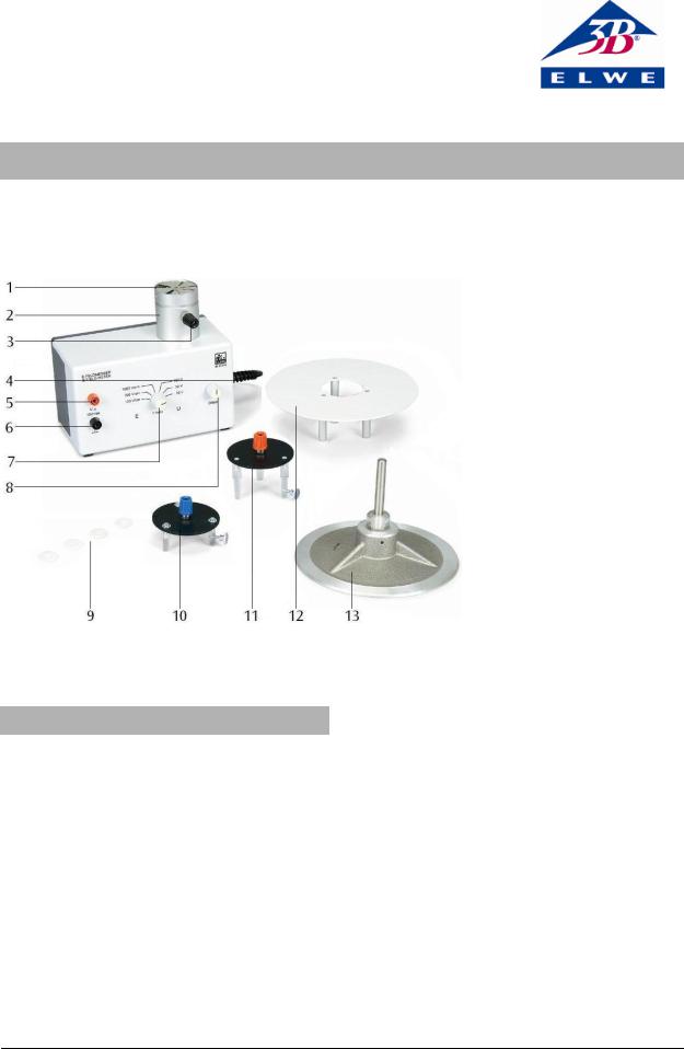
1Abschirmplatte
2Abschirmzylinder
3Massebuchse
4Netzschalter (nicht sichtbar)
5Spannungsausgang
6Massebuchse Spannungsausgang
7Messbereichswahlschalter
8Offsetregler
9Satz Abstandsscheiben aus Plexiglas
10Spannungsmessplatte, Messbereich 1x
11Spannungsmessplatte, Messbereich 10x
12Kondensator-Messplatte, 250 cm²
13Kondensatorplatte, 250 cm²
•Vor Erstinbetriebnahme überprüfen, ob der auf der Gehäuse-Rückseite aufgedruckte Wert für die Netzanschlussspannung den örtlichen Anforderungen entspricht.
•Vor Inbetriebnahme das Gehäuse und die Netzleitung auf Beschädigungen untersuchen und bei Funktionsstörungen oder sichtbaren Schäden das Gerät außer Betrieb setzen und gegen unbeabsichtigten Betrieb sichern.
•Gerät nur an Steckdosen mit geerdetem Schutzleiter anschließen.
•Kondensatorplatte und Spannungsmessplatte nur bei ausgeschaltetem Gerät aufsetzen.
1
2. Beschreibung
Der E-Feldmesser dient zur statischen Messung elektrischer Feldstärken oder elektrischer Spannungen.
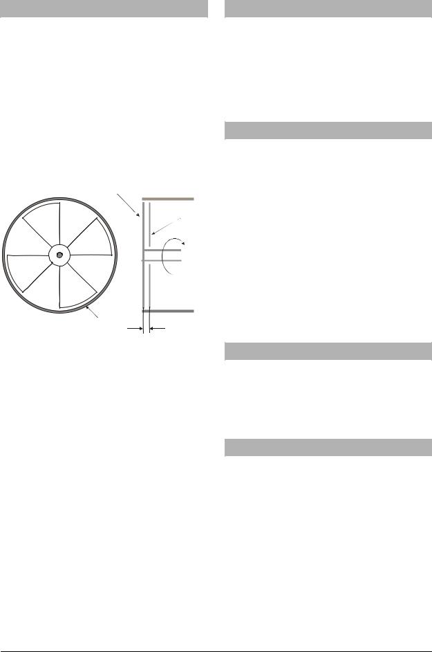
1. Messprinzip zur Messung der elektrischen Feldstärke: Vor einer Sonde mit vier sternförmig angeordneten Sektoren (Influenzplatte) dreht sich eine gleich geformte Abschirmplatte. Auf diese Weise wird ein auf die Sonde wirkender elektrischer Fluss ständig unterbrochen und auf der Sonde entstehen periodisch Influenzladungen, die über einen hochohmigen Widerstand abfließen. Die so erzeugten Spannungsimpulse werden im Gerät verstärkt und gleichgerichtet. Die Ausgangsspannung ist der Influenzspannung und damit der auf die Sonde wirkenden elektrischen Feldstärke proportional.
A
B
C
1 mm
Fig. 1 A Abschirmplatte, B Influenzplatte, C Abschirmzylinder
Als Anzeigeinstrument kann ein üblicher Gleichspannungsmesser (Messbereich 1 V oder 3 V) verwendet werden. 1 Volt Anzeigespannung entspricht einer elektrischen Feldstärke von 100 V/cm, 300 V/cm oder 1000 V/cm, umschaltbar am Drehschalter im Bereich „E“.
2. Messprinzip des E-Feldmessers als InfluenzElektrometer: Eine Kondensatorplatte (Spannungsmessplatte) wird in einem genau definierten Abstand von der Sonde angeordnet. Sie bildet zusammen mit der Sonde einen Kondensator, dessen elektrische Feldstärke eine Funktion der Kondensatorspannung und des Plattenabstandes ist.
Eine an die Spannungsmessplatte angelegte Spannung wird in den Schalterstellungen „U" angezeigt. Verwendet man die Spannungsmessplatte mit kleinem Abstand, so entspricht 1 Volt Anzeigespannung je nach Schalterstellung im Bereich „U“ einer Messspannung von 10 V, 30 V oder 100 V. Bei der Spannungsmessplatte mit großem Abstand erweitert sich der Messbereich um den Faktor 10.
Das Gerät ist gegen Überspannung, auch bei Funkenüberschlag, voll geschützt.
3. Lieferumfang
1 E-Feld-Messer Grundgerät
1 Spannungsmessplatte, Messbereich 1x
1 Spannungsmessplatte, Messbereich 10x
1 Kondensator-Messplatte, 250 cm2
1 Kondensatorplatte auf Stiel, 250 cm2
20 Abstandscheiben aus Plexiglas, 1 mm
4. Technische Daten
Betriebsspannung: |
siehe Geräterückseite |
Ausgangsspannung: |
max. 10 V |
Messbereiche (1 V Ausgangsspannung entspricht): |
|
|
100 V/cm, 300 V/cm, |
|
1000 V/cm |
|
10 V, 30 V, 100 V (mit |
|
Spannungsmessplatte 1x) |
|
100 V, 300 V, 1000 V (mit |
|
Spannungsmessplatte 10x) |
Eingangswiderstand: |
10 MΩ |
Abmessungen: |
ca. 140 x 110 x 70 mm3 |
Masse: |
ca. 1 kg |
Der E-Feldmesser U8533015-115 ist für eine Netzspannung von 115 V (±10 %) ausgelegt, U8533015-230 für 230 V (±10 %).
5. Empfohlenes Zubehör
Analog-Multimeter AM50 |
U17450 |
Zubehör zum E-Feldmesser |
U8533050 |
Kontaktstab |
U8497730 |
Widerstand 300 kΩ |
U51013 |
6.Bedienung
6.1Allgemeine Hinweise
•Wenn immer möglich mit nicht berührungsgefährlicher Spannung experimentieren.
•Bei Einsatz von Netzgeräten, die eine berührungsgefährliche Spannung liefern, den Widerstand (U51013) zur Strombegrenzung verwenden.
•Bei allen Messungen den Kontaktstab mit der Massebuchse am Abschirmzylinder verbinden und in die Hand nehmen, damit der Experimentator auf dem gleichen Potenzial ist.
•Vor jeder Messreihe sollte eine Nullpunktkalibrierung des E-Feldmessers für jeden Messbereich vorgenommen werden.
2

•Nach Einstecken des Netzsteckers einige Minuten abwarten, bis das Gerät die Betriebstemperatur erreicht hat.
•Um eine Beschädigung des E-Feldmessers zu vermeiden, die rotierende Flügelscheibe nicht berühren!
•Isolierteile am Gerät und an den Messplatten sauber halten (nicht berühren) und bei hoher Luftfeuchtigkeit evtl. in einem Warmluftstrom (Fön) trocknen.
Bei Feldstärkemessungen ist zu beachten, dass die Influenzplatte tiefer liegt als die Abschirmplatte. Diese Differenz liegt bei d = ca. 1 mm und muss für genaue Messungen experimentell bestimmt und bei Messungen berücksichtigt werden. Die Feldstärke E berechnet sich aus der Spannung U und dem Plattenabstand d nach der Formel
E = U d + d
6.2 Nullpunktkalibrierung
•Nullpunktkalibrierung zuerst am Anzeigeinstrument durchführen (siehe entsprechende Bedienungsanleitung).
•Anzeigeinstrument an den Spannungsausgang des E-Feldmessers anschließen.
•Spannungsmessplatte mit kleinem Abstand aufsetzen und mittels der Rändelschraube fixieren.
•Messbereichswahlschalter in der Schalterstellung „U" auf den größten Messbereich einstellen.
•Messplatte mit der Massebuchse am Abschirmzylinder verbinden.
•E-Feldmesser einschalten und mittels des Offsetreglers den Nullpunkt einstellen.
•Nullpunktkalibrierung in der gleichen Weise in den kleineren Messbereichen durchführen.
6.3Messung der Feldstärke eines Plattenkondensators
Zur Durchführung des Experiments ist ein DCNetzgerät erforderlich, das eine geglättete Spannung liefert z.B.
1 |
DC Netzgerät 500 V |
U33000-115 |
oder |
|
|
1 |
DC Netzgerät 500 V |
U33000-230 |
1 |
Widerstand 300 kΩ |
U51013 |
1 |
Kontaktstab |
U8497730 |
•Experimentieraufbau gemäß Fig. 2 herstellen.
•Anzeigeinstrument am Spannungsausgang des E- Feldmessers anschließen.
•Kondensator-Messplatte auf den Abschirmzylinder setzen und mit der Rändelschraube fixieren.
•Abstandsscheiben auf die Kondensator-Messplatte und darauf die Kondensatorplatte legen.
•Pluspol des DC-Netzgeräts mit der Kondensatorplatte und Minuspol mit der Massebuchse am Abschirmzylinder verbinden.
•Messbereichswahlschalter in der Schalterstellung „E" auf den gewünschten Messbereich einstellen.
•E-Feldmesser und Netzgerät einschalten.
•Verbindung zwischen Experimentator und Massebuchse am Abschirmzylinder herstellen.
•Messung durchführen.
•Gemessene Feldstärke mit dem theoretischen Wert vergleichen.
•Zum Nachweis der Abhängigkeit der Feldstärke vom Plattenabstand mit Hilfe der Abstandsscheiben verschiedene Plattenabstände herstellen und Messungen durchführen.
•Nach dem Experiment die Kondensatorplatte entladen. Dazu die Kondensatorplatte mit dem Abschirmzylinder verbinden.
6.4Spannungsmessung mit dem Influenzelektrometer
Zusätzlich erforderlich:
1 |
Hochspannungsnetzgerät 5 kV |
U33010-115 |
oder |
|
|
1 |
Hochspannungsnetzgerät 5 kV |
U33010-230 |
1 |
Widerstand 300 kΩ |
U51013 |
1 |
Kontaktstab |
U8497730 |
•Experimentieraufbau gemäß Fig. 3 herstellen.
•Anzeigeinstrument am Spannungsausgang des E- Feldmessers anschließen.
•Je nach Höhe der zu messenden Spannung entsprechende Spannungsmessplatte auf den Abschirmzylinder setzen und mit der Rändelschraube fixieren.
•Pluspol des Netzgeräts mit der Spannungsmessplatte Minuspol mit der Massebuchse am Abschirmzylinder verbinden.
•Messbereichswahlschalter in der Schalterstellung „U" auf den gewünschten Messbereich einstellen.
•E-Feldmesser und Netzgerät einschalten.
•Verbindung zwischen Experimentator und Massebuchse am Abschirmzylinder herstellen.
•Messung durchführen.
•Nach dem Experiment die Spannungsmessplatte entladen. Dazu die Spannungsmessplatte mit dem Abschirmzylinder verbinden.
3
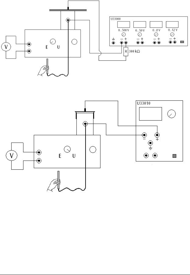
Fig. 2 Bestimmung der Feldstärke eines Plattenkondensators.
Fig. 3 Spannungsmessung mit dem Influenzelektrometer
Elwe Didactic GmbH • Steinfelsstr. 6 • 08248 Klingenthal • Deutschland • www.elwedidactic.com 3B Scientific GmbH • Rudorffweg 8 • 21031 Hamburg • Deutschland • www.3bscientific.com Technische Änderungen vorbehalten
© Copyright 2008 3B Scientific GmbH
3B SCIENTIFIC® PHYSICS
Electric Field Meter U8533015
Instruction Sheet
02/08 ALF
1 Shielding plate
2 Screening cylinder
3 Earth socket
4 Mains switch (not visible)
5 Output voltage socket
6 Earth socket for output
7 Measurement range switch
8 Offset adjustment
9 Set of Plexiglas spacer discs
10 Voltage measurement plate for
1× range
11 Voltage measurement plate for
10× range
12 Capacitor plate for voltage measurements, 250 cm²
13 Capacitor plate, 250 cm²
1. Safety Instructions
The electric field meter complies with the safety requirements of DIN EN 61010, part 1, relating to electrical measurement, control and regulation applications and for laboratory instruments, and its design complies with protection class I. It is designed for operation in dry environments suitable for working electricity.
Safety is guaranteed if the instrument is used as stipulated. However, safety cannot be guaranteed in cases of incorrect or careless operation.
If there is reason to suspect that safe operation is no longer assured, the instrument must be taken out of use immediately.
In schools and other educational establishments, the instrument may only be used under the supervision of a responsible person.
•Before using the instrument for the first time, check that the local mains voltage corresponds with that printed on the back of the housing.
•Before using the instrument, examine the housing and the mains cable. If there is visible damage or if the instrument does not function properly, take it out of service and secure it to prevent unauthorised use.
•The instrument may only be plugged in at a mains socket with an earth connection.
•The capacitor plate and the voltage measurement plate must only be put in place when the instrument is switched off.
1
2. Description
The electric field meter is used for the measurement of electrostatic field intensities or voltages.
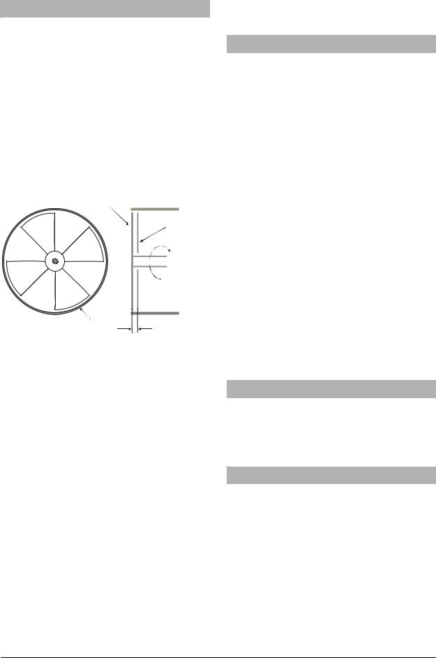
1. The principle for measuring electric field strength is as follows: A shielding plate with four vanes distributed in the shape of a star (induction plate) is rotated in front of a detector plate (probe) of similar shape. This arrangement means that the electric flux surrounding the detector plate is continually interrupted, so that an induced charge is generated intermittently on the detector plate. This periodically occurring charge is conducted away through a highvalue resistor. The voltage pulses thus generated are amplified and rectified. The resulting output voltage is proportional to the induced voltage, and therefore to the strength of the electric field acting on the detector plate.
A
B
C
1 mm
Fig. 1 A Shielding plate, B Induction plate, C Screening cylinder
An ordinary DC voltmeter (with measurement ranges 1 V and 3 V) can be used to display the results. The 1V range corresponds to electric field strength ranges of 100 V/cm, 300 V/cm or 1000 V/cm, selected by turning the rotary selector switch knob to one of the three “E” positions.
2. The principle of the electric field meter when used as an induction electrometer is as follows: A capacitor plate (the voltage measurement plate) is positioned at a precisely defined distance from the detector plate (probe). The combination of the two forms a capacitor, and the electric field strength within it is a function of the capacitor voltage and the distance between the plates.
With the range switch set to one of the “U” positions, a voltage applied to the voltage measurement plate is indicated on the voltmeter. When the voltage measurement plate is positioned at the shorter of the two distances, a meter reading of 1 volt corresponds to a measured voltage of 10 V, 30 V or 100 V, depending on the position of the switch in the “U” range. When the voltage measurement plate is positioned at the greater distance, the measurement ranges are increased by a factor 10.
The instrument is fully protected against excess voltage, even if a spark discharge occurs.
3. Equipment Supplied
1 Electric field meter, basic instrument
1 Voltage measurement plate for measurement range
1×
1 Voltage measurement plate for measurement range
10×
1 Capacitor plate for voltage measurements, 250 cm2
1 Capacitor plate on stem, 250 cm2
20 Plexiglas spacer discs, 1 mm
|
4. Technical Data |
|
|
|
|
Operating mains voltage: see back of instrument |
|
Output voltage: |
max. 10 V |
Measurement ranges (corresponding to 1V output): |
|
|
100 V/cm, 300 V/cm, |
|
1000 V/cm |
|
10 V, 30 V, 100 V (with voltage |
|
measurement plate 1x) |
|
100 V, 300 V, 1000 V (with |
|
voltage measurement plate 10x) |
Input resistance: |
10 MΩ |
Dimensions: |
140×110×70 mm3 approx. |
Weight: |
1 kg approx. |
The U8533015-230 electric field meter is designed for a mains voltage of 230V (±10%), and the U8533015115 model for 115V (±10%).
5. Recommended Accessories
Analog multimeter AM50 |
U17450 |
Accessories for the electric field meter |
U8533050 |
Contact rod |
U8497730 |
Resistor 300 kΩ |
U51013 |
6.Operation
6.1General instructions
•Whenever possible, conduct the experiments using voltages that are not dangerous to the touch.
•When using mains-connected instruments that generate a voltage that would be dangerous to touch, use a resistor (U51013) to limit the current.
•For all measurements, connect the contact rod to the earth socket on the screening cylinder and hold it in your hand, so that you are also at the same potential.
•Before each set of measurements, the zero-point of the electric field meter should be calibrated for all the measurement ranges.
2

•After plugging into the mains, wait a few minutes for the instrument to reach normal working temperature.
•To avoid damage to the electric field meter, do not touch the rotating vaned wheel.
•The insulating parts of the instrument and the measurement plates must be kept clean and dry (avoid touching them). When the air is very humid, it may be necessary to dry them in a current of warm air (use a hair-dryer).
For measurements of electric field strength, the induction plate should be positioned below the screening plate. The difference d is approximately 1 mm, and for precise measurements it must be determined experimentally and taken into account in the measurements. The field strength E is calculated from the voltage U and the distance d between the plates according to the formula
E = U . d + d
6.2 Zero-point calibration
•First calibrate the zero-point for the indicating instrument (e.g., a voltmeter – see relevant instruction sheet).
•Connect the indicating instrument to the voltage output of the electric field meter.
•Place the voltage measurement plate in position at the shorter distance and secure it with the knurled screw.
•Turn the measurement range switch to the “U” position and set to the highest range.
•Connect the measurement plate to the earth socket of the screening cylinder.
•Switch on the electric field meter and set the zero point using offset adjustment.
•Calibrate the zero-point for the two lower measurement ranges by the same procedure.
6.3 Measurement of the field strength in a plate capacitor
This experiment requires a DC power supply with a smoothed voltage outout, for example:
1 |
DC power supply, 500 V |
U33000-230 |
or |
|
|
1 |
DC power supply, 500 V |
U33000-115 |
1 |
Resistor 300 kΩ |
U51013 |
1 |
Contact rod |
U8497730 |
•Set up the experiment as shown in Fig. 2.
•Connect the indicating instrument to the voltage output of the electric field meter.
•Place the capacitor plate for voltage measurements on the screening cylinder and secure it with the knurled screw.
•Place the required spacer discs on the capacitor
plate for voltage measurements and place the other capacitor plate on top.
•Connect the positive output terminal of the DC power supply to the upper capacitor plate and the negative output terminal to the earth socket of the screening cylinder.
•Turn the measurement range switch to the “E” position and select the required range.
•Switch on the electric field meter and the DC power supply.
•Make a connection between the person conducting the experiment and the earth socket of the screening cylinder.
•Carry out the measurement.
•Compare the measured field strength with the theoretical value.
•Make a series of similar measurements with different distances between the plates using the spacer discs, to demonstrate the dependence of the field strength on the plate separation.
•After the experiment, discharge the capacitor plate by connecting it to the screening cylinder.
6.4Measurement of voltages using the instrument as an induction electrometer
Additional equipment required:
1 |
High voltage power supply, 5 kV |
U33010-230 |
or |
|
|
1 |
High voltage power supply, 5 kV |
U33010-115 |
1 |
Resistor 300 kΩ |
U51013 |
1 |
Contact rod |
U8497730 |
•Set up the experiment as shown in Fig. 3.
•Connect the indicating instrument to the voltage output of the electric field meter.
•Depending on the voltage to be measured, place the appropriate voltage measurement plate on the screening cylinder and secure it with the knurled screw.
•Connect the positive output terminal of the high voltage power supply to the voltage measurement plate and the negative output terminal to the earth socket of the screening cylinder.
•Turn the measurement range switch to the “U” position and select the required range.
•Switch on the electric field meter and the high voltage power supply.
•Make a connection between the experimenter and the earth socket of the screening cylinder.
•Carry out the measurement.
•After the experiment, discharge the voltage measurement plate by connecting it to the screening cylinder.
3

Fig. 2 Determining the field strength inside a plate capacitor
Fig. 3 Voltage measurement using the instrument as an induction electrometer
Elwe Didactic GmbH • Steinfelsstr. 6 • 08248 Klingenthal • Germany • www.elwedidactic.com 3B Scientific GmbH • Rudorffweg 8 • 21031 Hamburg • Germany • www.3bscientific.com Subject to technical amendments.
© Copyright 2008 3B Scientific GmbH
 Loading...