


WELLS BLOOMFIELD, LLC |
164 |
2 ERIK CIRCLE, P. O. Box 280 Verdi, NV 89439 telephone: 775-689-5703
fax: 775-689-5976 www.wellsbloomfield.com
Model HDCR-2436G
OPERATION MANUAL
HEAVY DUTY GAS CHAR-ROCK CHARBROILER
MODELS:
HDCR-1230G
HDCR-2430G
HDCR-3630G
HDCR-4830G
Includes
INSTALLATION
USE & CARE
FOR YOUR SAFETY
Do not store gasoline or other flammable liquids in the vicinity of this or any other appliance.
WARNING:
Improper installation, adjustment, alteration, service or maintenance can cause property damage, injury or death. Read the installation, operating and maintenance instructions thoroughly before installing or servicing this equipment.
IMPORTANT:
The purchaser of this equipment must post in a prominent location instructions to be followed in the event the user smells gas. This information shall be obtained by consulting the local gas supplier.
IMPORTANT: DO NOT DISCARD THIS MANUAL
This manual is considered to be part of the appliance and is to be given to the OWNER or MANAGER of the restaurant, or to the person responsible for TRAINING OPERATORS of this appliance. Additional manuals are available from your WELLS DEALER.
THIS MANUAL MUST BE READ AND UNDERSTOOD BY ALL PERSONS USING OR INSTALLING THIS APPLIANCE. Contact your WELLS DEALER if you have any questions concerning installation, operation or maintenance of this equipment.
|
PRINTED IN CHINA |
p/n 307737 Rev. (-) ECN-xxxxx |
M164 081103 cps |

ENGLISH
LIMITED WARRANTY STATEMENT
Unless otherwise specified, all commercial cooking equipment manufactured by WELLS BLOOMFIELD, LLC is warranted against defects in materials and workmanship for a period of one year from the date of original installation or 18 months from the date of shipment from our factory, whichever comes first, and is for the benefit of the original purchaser only.
THIS WARRANTY IS THE COMPLETE AND ONLY WARRANTY, EXPRESSED OR IMPLIED IN LAW OR IN FACT, INCLUDING BUT NOT LIMITED TO, WARRANTIES OF MERCHANTABILITY OR FITNESS FOR ANY PARTICULAR PURPOSE, AND/OR FOR DIRECT, INDIRECT OR CONSEQUENTIAL DAMAGES IN CONNECTION WITH WELLS BLOOMFIELD PRODUCTS. This warranty is void if it is determined that, upon inspection by an authorized service agency, the equipment has been modified, misused, misapplied, improperly installed, or damaged in transit or by fire, flood or act of God. It also does not apply if the serial nameplate has been removed, or if service is performed by unauthorized personnel. The prices charged by Wells Bloomfield for its products are
based upon the limitations in this warranty. Seller’s obligation under this warranty is limited to the repair of defects without charge by a Wells Bloomfield factory authorized service agency or one of its sub-service agencies. This service will be provided on customer’s premises for non-portable models. Portable models (a device with a cord and plug) must be taken or shipped to the closest authorized service agency, transportation charges prepaid, for service. In addition to restrictions contained in this warranty, specific limitations are shown in the Service Policy and Procedure Guide. Wells Bloomfield authorized service agencies are located in principal cities. This warranty is valid in the United States and Canada and void elsewhere. Please consult your classified telephone directory, your foodservice equipment dealer or contact:
Service Department, Wells Bloomfield, LLC P.O. Box 280, Verdi, Nevada 89439
phone (775) 689-5707 or fax (775) 689-5976
for information and other details concerning warranty.
SERVICE POLICY AND PROCEDURE GUIDE and ADDITIONAL WARRANTY EXCLUSIONS
1.Resetting of safety thermostats, circuit breakers, over load protectors, and/or fuse replacements are not covered by this warranty unless warranted conditions are the cause.
2.All problems due to operation at voltages or phase other than specified on equipment nameplates are not covered by this warranty.
Conversion to correct voltage and/or phase must be the customer’s responsibility.
3.All problems due to electrical connections not made in accordance with electrical code requirements and wiring diagrams supplied with the equipment are not covered by this warranty.
4.Replacement of items subject to normal wear, to include such items as knobs, light bulbs; and, normal maintenance functions including adjustments of thermostats, adjustment of micro switches and replacement of fuses and indicating lights are not covered by warranty.
5.Damage to electrical cords and/or plug due to exposure to excessive heat are not covered by this warranty.
6.Full use, care, and maintenance instructions supplied with each machine. Noted maintenance and preventative maintenance items, such as servicing and
cleaning schedules, are customer responsibility. Those miscellaneous adjustments noted are customer responsibility. Proper attention to preventative maintenance and scheduled maintenance procedures will prolong the life of the appliance.
7.Travel mileage is limited to sixty (60) miles from an Authorized Service Agency or one of its sub-service agencies.
8.All labor shall be performed during regular working hours. Overtime premium will be charged to the buyer.
9.All genuine Wells replacement parts are warranted for ninety (90) days from date of purchase on nonwarranty equipment. This parts warranty is limited only to replacement of the defective part(s). Any use of non-genuine Wells parts completely voids any warranty.
10.Installation, labor, and job check-outs are not considered warranty and are thus not covered by this warranty.
11.Charges incurred by delays, waiting time or operating restrictions that hinder the service technician’s ability to perform service are not covered by warranty. This includes institutional and correctional facilities.
SHIPPING DAMAGE CLAIM PROCEDURE
NOTE: For your protection, please note that equipment in this shipment was carefully inspected and packaged by skilled personnel before leaving the factory. Upon acceptance of this shipment, the transportation company assumes full responsibility for its safe delivery.
IF SHIPMENT ARRIVES DAMAGED:
1.VISIBLE LOSS OR DAMAGE: Be certain that any visible loss or damage is noted on the freight bill or express receipt, and that the note of loss or damage is signed by the delivery person.
2.FILE CLAIM FOR DAMAGE IMMEDIATELY:
Regardless of the extent of the damage.
3. CONCEALED LOSS OR DAMAGE: if damage is unnoticed until the merchandise is unpacked,
notify the transportation company or carrier immediately,
and file |
“CONCEALED DAMAGE” claim with them. This |
|
should be done within fifteen (15) days from the |
date |
the delivery was made to you. Be sure to retain |
the |
container for inspection. |
Wells Bloomfield cannot assume liability for damage or loss incurred in transit. We will, however, at your request, supply you with the necessary documents to support your claim.
Broilers Rock-Char Series-HDCR for OpManual 307737 164
xi

164 307737 OpManual for HDCR-Series Char-Rock Broilers
TABLE OF CONTENTS
ENGLISH
WARRANTY |
xi |
SPECIFICATIONS |
1 |
FEATURES & OPERATING CONTROLS |
2 |
PRECAUTIONS & GENERAL INFORMATION |
3 |
AGENCY LISTING INFORMATION |
3 |
INSTALLATION |
4 |
OPERATION |
8 |
CLEANING INSTRUCTIONS |
10 |
TROUBLESHOOTING SUGGESTIONS |
12 |
PARTS & SERVICE |
13 |
CUSTOMER SERVICE DATA |
13 |
FRANÇAIS |
|
DESCRIPTION ET AVERTISSEMENTS DE SÛRETÉ |
14 |
SPÉCIFICATIONS |
15 |
FONCTIONNALITÉS ET COMMANDES |
16 |
PRÉCAUTIONS & RENSEIGNEMENTS D’ORDRE |
|
GÉNÉRAL |
17 |
INFORMATIONS CONCERNANT LES AGENCES |
17 |
INSTALLATION |
18 |
FONCTIONNEMENT |
22 |
INTRODUCTION
Thank You for purchasing this Wells Bloomfield appliance.
Proper installation, professional operation and consistent maintenance of this appliance will ensure that it gives you the very best performance and a long, economical service life.
This manual contains the information needed to properly install this appliance, and to use and care for the appliance in a manner which will ensure its optimum performance.
SPECIFICATIONS
MODEL |
STYLE |
FUEL |
MANIFOLD |
B.T.U. |
|
PRESSURE |
per HOUR |
||||
|
|
|
|||
|
|
|
|
|
|
HDCR-1230G |
2 Burners w/ |
Natural Gas |
5.0” W.C. |
40,000 |
|
|
|
|
|||
Individual Control |
Propane (LP) |
10” W.C. |
30,000 |
||
|
|||||
|
|
||||
|
|
|
|
|
|
HDCR-2430G |
4 Burners w/ |
Natural Gas |
5.0” W.C. |
80,000 |
|
|
|
|
|||
Individual Control |
Propane (LP) |
10” W.C. |
60,000 |
||
|
|||||
|
|
||||
|
|
|
|
|
|
HDCR-3630G |
6 Burners w/ |
Natural Gas |
5.0” W.C. |
120,000 |
|
|
|
|
|||
Individual Control |
Propane (LP) |
10” W.C. |
90,000 |
||
|
|||||
|
|
||||
|
|
|
|
|
|
HDCR-4830G |
8 Burners w/ |
Natural Gas |
5.0” W.C. |
160,000 |
|
|
|
|
|||
Individual Control |
|
|
|
||
Propane (LP) |
10” W.C. |
120,000 |
|||
|
|||||
|
|
||||
|
|
|
|
|
ENGLISH
1

FEATURES & OPERATING CONTROLS
SPLASH GUARD
CHAR-ROCK
STONES
SUPPORT
GRID
ADJUSTABLE
LEG
GREASE TROUGH
GAS PRESSURE
REGULATOR
GREASE
DEFLECTOR 
 MAIN BURNER


REFLECTOR 
PILOT BURNER
AIR ADJUSTMENT SHUTTER
GRATE - RAISED POSITION
GRATE - NORMAL POSITION
GREASE DISCHARGE
CHUTE
DRIP PAN
CONTROL KNOB “OFF” POSITION
CONTROL KNOB “ON” POSITION
GAS
MANIFOLD
GAS CONTROL VALVE
PILOT FLAME ADJUST
Fig. 1 Heavy Duty Gas Char-Rock Broiler - Features & Operating Controls
Broilers Rock-Char Series-HDCR for OpManual 307737 164
2

164 307737 OpManual for HDCR-Series Char-Rock Broilers
PRECAUTIONS AND GENERAL INFORMATION
This appliance is intended for use in commercial establishments only.
This appliance is intended to prepare food for human consumption. No other use is recommended or authorized by the manufacturer or its agents.
This appliance must be installed by a technician qualified and certified or licensed to install gas-fired equipment. A licensed technician must perform the initial start-up and adjustment of the appliance.
Operators of this appliance must be familiar with the appliance use, limitations and associated restrictions. Operating instructions must be read and understood by all persons using or installing this appliance.
Cleanliness of this appliance is essential to good sanitation. Read and follow all included cleaning instructions and schedules to ensure the safety of the food product.
DO NOT submerge appliance or burners in water. This appliance is not jet stream approved. DO NOT direct water jet or steam jet at this appliance, or at any control. DO NOT splash or pour water on, in or over any controls. DO NOT wash counter around this appliance with water jet. Burners which have become wet must be thoroughly dried before use.
Griddle surface will be very hot when in use. Contact will cause severe injury.
This appliance must be operated with the supplied 4” legs properly installed. Do not operate the appliance without legs installed.
Do not operate this appliance if the smell of gas is present. Turn off all gas supply valves and move to a remote location to call your Authorized Wells Service Agent for service.
The technical content of this manual, including any parts breakdown illustrations and/or adjustment procedures, is intended for use by qualified technical personnel only.
Any procedure which requires the use of tools must be performed by a qualified technician.
This manual is considered to be a permanent part of the appliance. This manual and all supplied instructions, diagrams, schematics, parts breakdown illustrations, notices and labels must remain with the appliance if it is sold or moved to another location.
 WARNING:
FIRE HAZARD
All servicing of the gas supply and combustion components of this appliance must be performed by a technician trained and certified in the maintenance of gas appliances.
Improper servicing of gas equipment can result in fire and explosion.
WARNING:
 HEALTH and FIRE
HAZARD
Appliance must have legs installed to insure proper combustion. Operation without legs installed can lead to fire, injury and death.
CAUTION:
HOT SURFACE
Exposed surfaces can be hot to the touch and may cause burns.
AGENCY LISTING INFORMATION
This appliance conforms to NSF Standard 4 for sanitation only if installed in accordance with the supplied Installation Instructions and maintained according to the instructions in this manual.
This appliance meets ANSI Z.83.11 specifications for gas-fired food |
STD 4 |
service equipment. |
|
This appliance is Canadian Standards Association design certified for gas operation
3 


ENGLISH
INSTALLATION
NOTE: DO NOT discard the carton or other packing materials until you have inspected the appliance for hidden damage and tested it for proper operation.
Refer to SHIPPING DAMAGE CLAIM PROCEDURE on the inside front cover of this manual.
DANGER:
HEALTH
HAZARD
This appliance must be properly ventilated. Failure to provide and maintain proper ventilation of exhaust gasses can result in severe injury or death.
 WARNING:
FIRE HAZARD
Do not store gasoline or any other flammable or
combustible material near this appliance. The open flame can cause such materials to ignite.
The area where the griddle is installed must be kept clear of combustibles and flammables. This includes mops, rags, grease, wrapping paper and electric cords.
NOTICE: Manufacturer’s warranty on this charbroiler is in effect only when the griddle is installed in accordance with these instructions and local codes and ordinances or, in the absence of local codes, the National Fuel Gas Code, ANSI Z223.1 (current edition). The manufacturer of this griddle assumes no liability for any damage or injury resulting from failure to comply with this notice.
UNPACKING & INSPECTION
Carefully remove the appliance from the carton. Remove all protective plastic film, packing materials and accessories from the appliance before connecting performing any installation procedure.
Carefully read all instructions in this manual and the Installation Instruction Sheet packed with the appliance before starting any installation.
Read and understand all labels and diagrams attached to the appliance.
Carefully account for all components and accessories before discarding packing materials. Store all accessories in a convenient place for later use.
COMPONENTS
Grates, Support Grids, Grease Deflectors and Burners (12", 2 ea.; 24", 4 ea.; 36", 6 ea.; 48", 8 ea.)
Char-Rock Stones
(-12", 3 lbs.; 24", 6 lbs.; 36", 9 lbs.; 48", 12 lbs.) Adjustable Legs (set of 4)
Drip Tray
Wire Brush
SETUP
This appliance is designed for use in non-combustible locations only. Setup the hotplate only on a firm, level, non-combustible surface.
Verify local codes for requirements. Concrete, tile, terrazzo or metal surfaces are recommended. Metal or tile over combustible material may not meet code for non-combustible surfaces.
Clearances to non-combustible surfaces must be maintained.
Maintain 0” from side and rear to non-combustible walls, and 4” from non-combustible counter as established by provided 4” legs.
Maintain adequate clearances for cleaning and proper operation.
The hotplate must be installed in an area with sufficient make-up air for proper combustion, and must be installed such that the flow of combustion and ventilation air will not be obstructed.
For servicing, Wells Mfg. recommends 6” clearance from rear of the appliance to wall.
Install adjustable legs, one on each corner of the appliance, in the holes provided.
Verify that the unit sits firmly ON ALL FOUR LEGS. With the adjustable legs, adjust as
required to level the appliance. All four legs must be adjusted to firmly contact the floor in order to prevent tipping.
When used with an exhaust fan, special
precautions must be observed to avoid interference with the operation of the char-
broiler,
such as drafts and air starvation.
Broilers Rock-Char Series-HDCR for OpManual 307737 164
4

164 307737 OpManual for HDCR-Series Char-Rock Broilers
|
INSTALLATION (continued) |
GAS APPLIANCE CODE COMPLIANCE |
DANGER: |
The installation of gas piping from the outlet side of the gas meter or |
FIRE AND |
EXPLOSION |
|
service regulator to the charbroiler must be performed by a technician |
HAZARD |
qualified and certified or licensed to install gas-fired equipment. |
NEVER use an open flame to |
A licensed and qualified technician must perform the initial startup and |
check for gas leaks. Fire and |
explosion may result. |
|
adjustment of this appliance. |
|
The installation of this gas-fired appliance must conform to local codes, or in the absence of such codes, with the current edition of
National Fuel Gas Code ANSI Z223.1.
For use in the State of Massachusetts, this appliance must be installed in compliance with Massachusetts Fuel Gas and Plumbing Code
CMR 248.
The installation of this gas-fired appliance must comply with applicable portions of NFPA 96 for ventilation. The current edition of NFPA 96 (Standard for the Installation of Equipment for the Removal of Smoke and Grease Laden Vapors from Commercial Cooking Equipment) specifies ventilation requirements to ensure the removal of exhaust gasses and products of combustion.
IT IS THE RESPONSIBILITY OF THE INSTALLER TO ENSURE THAT THIS GAS BROILER INSTALLATION CONFORMS TO ALL APPLICABLE CODES AND ORDINANCES.
The venting of this appliance must not be obstructed, nor may such venting interfere with the flow of combustion air required for proper operation of the gas burners.
Additionally:
1.The gas supply line used to connect the appliance to the gas supply system must be black iron pipe, or other material as approved by local ordinance for gas piping.
2.Gas supply piping must be 3/4” inside diameter or greater.
3.Use pipe sealant made specifically for gas piping on all pipe
joints. Apply sealant sparingly to the male threads only. Sealant must be resistant to the action of LP gas.
4.Verify that all supply piping is clean and free of obstructions, dirt, chips and pipe sealant compound prior to installation.
5.All pipe joints must be checked for leaks before lighting. Leak checks should be performed with a soap and water solution. NEVER CHECK FOR LEAKS WITH AN OPEN FLAME.
6.This appliance must be installed so that there is adequate and proper clearance for operation and servicing.
 WARNING:
RISK OF INJURY
Installation procedures must be performed by a qualified technician with full knowledge of all applicable gas-fired appliance codes. Failure can result in personal injury and property damage.
IMPORTANT:
All pipe joints must be checked for leaks before lighting. Leak checks should be performed with a soap and water solution.
IMPORTANT:
Information on the construction and installation of ventilating hoods may be obtained from the current edition of NFPA 96
Standard for the Installation of Equipment for the Removal of Smoke and Grease Laden Vapors from Commercial Cooking Equipment.
Copies of this standard are available from the
Nation Fire Protection Assn.:
NFPA
1 Batterymarch Park
P.O. Box 9101
Quincy, MA 02269-9101
ENGLISH
5
ENGLISH
INSTALLATION (continued)
DANGER:
FIRE AND
EXPLOSION HAZARD
NEVER use an open flame to check for gas leaks. Fire and explosion may result.
IMPORTANT:
All pipe joints must be checked for leaks before lighting. Leak checks should be performed with a soap and water solution.

 WARNING:
 FIRE HAZARD
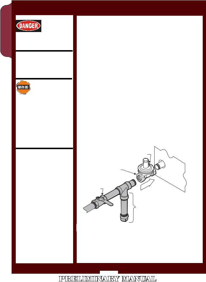
This appliance is supplied with a gas pressure regulator. Failure to properly install the supplied regulator will result in an extremely hazardous condition.
Flow arrow stamped on body of regulator must point toward the griddle.
Vent hole must point UP.
INSTALLING THE GAS GRIDDLE
Refer to the nameplate. Verify the fuel type and pressure, which must match the nameplate specifications. Connecting the hotplate to the wrong fuel type and/or pressure will compromise the safety and/or performance of the appliance.
BE SURE TO MAINTAIN REQUIRED CLEARANCES TO COMBUSTIBLE SURFACES.
The appliance must be placed in its final operational position and leveled front-to-back and side-to-side, with a spirit level, prior to beginning the gas piping installation. Re-check the level of the unit at the conclusion of the gas piping installation.
Each gas appliance is supplied with a separate gas pressure regulator, which must be installed on the manifold pipe protruding from the rear of the griddle. Ensure that the regulator is installed such that the flow arrow stamped on the body of the regulator points toward the griddle. Failure to properly install the supplied regulator will result in an extremely hazardous condition.
A moisture trap (drip leg) consisting of a tee, 4” nipple pointing down, and cap must be installed upstream of the gas pressure regulator.
A manual gas shut-off valve may be required by local codes and is, in any case, strongly recommended. The shut-off valve must be installed between the gas supply piping and the gas pressure regulator.
IMPORTANT:
Verify fuel gas type. If the available fuel does not match the nameplate specification, exchange the appliance for the correct type.
IMPORTANT:
The appliance and its individual manual shutoff valve must be disconnected from supply system piping during any pressure testing of that system at pressures in excess of 1/2 p.s.i. (3.5 kPa).
Also, the appliance must be isolated from the gas supply piping system by closing its individual manual shutoff valve during any pressure testing of the gas supply piping at test pressures equal to or less than 1/2 p.s.i. (3.5 kPa).
SUPPLIED
REGULATOR
GAS
SHUT-OFF
VALVE*
VENT
|
BACK |
OF |
BROILER |
|
|
||
FLOW |
|
|
|
DRIP LEG* |
|
GAS |
* by others |
|
SUPPLY* |
||
|
Fig. 2 Gas Supply Piping
It is the responsibility of the gas piping installer to identify the code requirement for a shut-off valve.
Shut-off valves, moisture trap and all associated piping must be supplied by the gas piping installer.
Broilers Rock-Char Series-HDCR for OpManual 307737 164
6
164 307737 OpManual for HDCR-Series Char-Rock Broilers
INSTALLATION (continued)
SET GAS PRESSURE:
Gas pressure regulator is factory set.
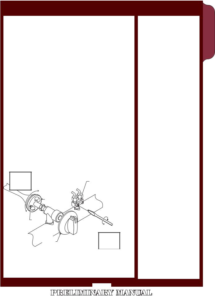
SET PILOT FLAME:
Remove all burner control knobs, then remove the front panel. Remove grates.
The pilot adjustments are near the control valve for each set of burners.
Using a small, flat-blade screwdriver, turn the screw clockwise to decrease the flame size, or counter-clockwise to increase the flame size.
Adjust the pilot flame to 1/4” high. Test for operation: all sections of the burner must light without undue delay. Drafty conditions may require a higher flame to allow the pilot to remain lit.
Replace the grates, front panel and all knobs before returning the unit to service.
ADJUST BURNER FLAME:
Remove all burner control knobs, then remove the front panel. Remove grates and radiants.
Turn an individual burner on.
Loosen the locking screw on the shutter.
Turn the shutter to admit more or less air as required. Adjust the air shutter until the flame is mostly blue in color.
Tighten the locking screw when finished. Replace tall grates and radiants, the front panel and all knobs before returning the unit to service.
BURNER |
PILOT |
|
FLAME |
FLAME |
|
ADJUST |
ADJUST |
|
|
||
LESS |
|
|
AIR |
|
|
SHUTTER |
|
|
MORE AIR |
LESS |
|
|
||
LOCKING |
FLAME |
|
SCREW |
|
|
|
MORE |
|
|
FLAME |
|
BURNER |
PILOT |
|
FLAME |
||
CONTROL |
||
KNOB |
ADJUST |
|
|
Fig. 3 Adjustments
IMPORTANT:
Adjustments must be performed by a qualified technician only.
IMPORTANT:
The appliance is shipped from the factory equipped for natural gas and adjusted for sea level to 2000 feet elevation.
For conversion to LP / Propane, or for operation above 2000 feet elevation, contact your Authorized Wells Service Agency.
ENGLISH
7
 Loading...