


IMACS Product Book
(PAGE INTENTIONALLY LEFT BLANK)
TABLE OF CONTENTS
Section: |
Title: |
Page |
|
|
: |
I.IMACS Product Overview
II. |
Chassis and Common Equipment |
14 |
|
|
1. |
IMACS Chassis and Backplane |
14 |
|
2. |
CPU Cards |
21 |
|
3. |
Interface Cards |
23 |
|
4. |
WAN Cards |
27 |
III. |
Voice Modules and Applications |
31 |
|
|
1. |
FXS |
31 |
|
2. |
FXO |
32 |
|
3. |
E&M |
34 |
|
4. |
P-Phone |
36 |
|
5. |
Voice Channel Bank Application |
39 |
IV. |
Data Modules and Applications |
41 |
|
|
1. |
HSU |
44 |
|
2. |
SRU |
47 |
|
3. |
FRAD |
50 |
|
4. |
OCU-DP |
53 |
|
5. |
BRI |
56 |
|
6. |
DSO-DP |
60 |
|
7. |
BnR IP Concentrator |
61 |
|
8. |
PM-IOR |
62 |
V. |
Alarm Cards |
64 |
|
TABLE OF CONTENTS CONTINUED
Section: |
Title: |
Page |
|
|
|
|
: |
VI. |
Server Cards |
65 |
|
|
1. |
ADPCM |
65 |
|
2. |
ISDN |
69 |
|
3. |
Management Channel Concentrator (MCC) |
77 |
|
4. |
ACS-FRS |
79 |
|
5. |
ATM |
85 |
|
6. |
Internet Protocol Router |
90 |
|
7. |
Low-Bit Rate Voice Server |
94 |
VII. |
IMACS System Testing and Diagnostics |
98 |
|
Zhone Technologies, Inc. |
IMACS Product Book, Version 4 |
I. IMACS Product Overview
IMACS
Zhone Technologies’ Integrated Multiple Access Communications Server (IMACS) is a highly flexible and intelligent Integrated Access Device (IAD) that enables service providers worldwide to offer a wide variety of business communication services efficiently and cost-effectively. Services include Plain Old Telephone Services (POTS), analog private lines, Digital Data Networks (DDN), Frame Relay, Integrated Services Digital Network (ISDN), Asynchronous Transfer Mode (ATM) based services, high-speed Internet access and integrated routing. The IMACS supports V.35, V.11/X.21, HDSL, T1, E1, fractional T1, fractional E1 and DS3 network interfaces. For user connectivity, a variety of interfaces are available to support analog and digital devices.
An integrated Digital Cross Connect is available to consolidate multiple voice, data and T1/E1 services. In addition, IMACS offers a powerful array of built-in network diagnostic and fault isolation capabilities. These include built-in Bit Error Rate Testers, test tone and signaling state generation, digital and analog loop-back support and remote configuration and control. The Server slots on the IMACS platform enable provisioning advanced services such as voice compression (ADPCM and ACELP), ISDN call handling, Frame Relay switching and concentration, MCC and ATM adaptation.
Three types of IMACS chassis are available. The IMACS 600, IMACS 800 and IMACS 900 differ in their card capacity and front or rear card install options. All models support the same range of modular cards, power supplies and system redundancy options. All IMACS systems can be fully managed either with local craft interface with a VT100 or PC or through a network management system using SNMP.
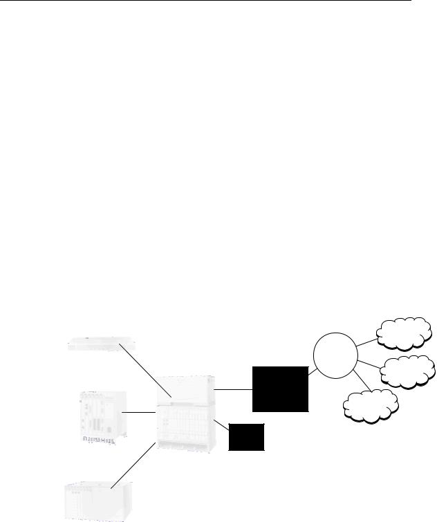
The IMACS is a component of a complete line of managed, integrated access solutions from Zhone Technologies. Figure 1 shows how the service provider can deliver a complete suite of fast, efficient and reliable business communication services to the customers by deploying the Sechtor 300, IMACS, the StreamLine and the Z-Plex 10.
|
|
|
Internet |
|
|
|
Sonet |
• ISDN |
Z-Plex 10 |
|
Ring |
|
|
||
|
|
ATM |
|
• POTS |
|
Add/Drop |
|
• Private Data |
|
Multiplexer |
|
|
|
|
|
• Private Voice |
|
|
PSTN |
• (PBX) |
|
|
|
• Frame Relay |
|
M13 |
|
• ATM |
StreamLine |
Secht |
|
• Internet |
|
|
|
|
3/1/0 DACS |
|
|
• Extranet |
|
|
|
|
GR303 NS.2 |
|
VT/VC Grooming
• Intranet
• Video
IMACS
Figure 1 - IMACS Product Family
March 2001 |
Page 1 |

Zhone Technologies, Inc. |
IMACS Product Book, Version 4 |
IMACS Features and Benefits
Flexibility and Intelligence
Global Standards Compliant—ensures product can be integrated in any international telecommunications network.
Provisioning for extensive array of services and applications—flexibility which enables providers to generate revenues without replacing existing equipment.
Concurrent support for Circuit, Packet, Frame, and Cell processing—single solution for service providers to use rather than purchasing and managing multiple boxes and networks.
Cost-effective migration path to emerging access services and technologies - investment protection.
SNMP Manageable—industry-wide accepted standard for network management a Remote software download capability—time and technical support resources savings.
Modular Architecture
Ease of service and capacity expansion—preserves existing investment and reduces any need to forklift upgrade from old equipment.
Flexibility of provisioning technologies using multi-bus architectureanalog, digital, packet, frame, cell, etc.— enables carriers to offer various services and be a “one-stop” provider which generates more revenues.
Interchangeable set of User, WAN, and Server cards determine application set.
Well-designed chassis to fit into a variety of standard racks.
Powerful User Interface and Remote Management Capabilities
Fully configurable through software—locally and remotely—eliminates need to send out technical support personnel to multiple sites, saving time and money.
Remote software upgrade capability on various cards—eliminates need to purchase new cards.
System Integrity Features
Low power consumption.
Single chassis redundancy of power supply, CPU, network interfaces and converter. Choice of clock synchronization sources with automatic clock fallback to alternate choice.
Ease of Maintenance and Enhancement
Multiple maintenance ports for WAN, data and voice modules.
Extensive system-wide built-in diagnostics and fault isolation tests.
Continuous alarm monitoring.
Local and remote alarm logging.
Easy access to customer technical support.
Hot swappable cards.
March 2001 |
Page 2 |

Zhone Technologies, Inc. |
IMACS Product Book, Version 4 |
IMACS Architecture Overview
The IMACS chassis architecture supports three types of buses and five card types. The buses are the:
•User
•WAN
•Server
Communicating through the buses are the following five card types:
•CPU
•WAN
•User
•Server
•Interface
Each system has at least one CPU, WAN and one Interface card. These three cards provide common functions for the shelf. The WAN, User, and Server cards provide the specific voice/data terminal and network interfaces and processing required by the customer to transfer voice and data traffic from the customer premise to the network. IMACS architecture has specific card slots, which are tailored to provide either a WAN, User or Server function.
IMACS System Bus Architecture
The IMACS is a multiprocessor-based platform that handles today’s network access needs and provides a migration path to the wide range of services of the future. A unique multi-bus architecture provides this flexibility by offloading and isolating the Wide Area Network (WAN) link processing tasks from those of inter-processor communications and channel I/O (input/output) control and signaling. The CPU card employs multiple communication buses extended through the back plane to the User, Server, WAN and Interface Cards. The CPU uses these buses to configure hardware on User, Server, WAN, or Interface cards and solicit status. Depending on the intelligence on the card, the CPU may either read or write to the card’s hardware registers or send and receive messages using a messaging protocol.
This design approach yields two significant advantages over other access multiplexers. First, the off-loading of processing tasks across the multi-bus reduces system overhead, thereby improving the effective throughput and performance. Second, the isolation of functions allows rapid design and development of new network access compatible WAN functions. As the new functions are introduced, they occupy the Server card slot and do not impact or disrupt an existing system. For instance, the design of the Frame Relay Server card was performed utilizing the Server processor bus and is independent of other existing or future IMACS functions. When a Frame Relay server card is installed, it can perform Frame Relay access concentration on WAN links and fractional channels assigned to the IMACS. Figure 2 shows a functional block diagram of the IMACS’s multi-bus architecture and the manner in which functions are isolated.
March 2001 |
Page 3 |

Zhone Technologies, Inc. |
|
|
|
|
|
|
|
|
|
|
|
|
|
|
|
|
|
IMACS Product Book, Version 4 |
||||||||||||||||||||||
|
|
|
|
|
|
|
|
|
|
|
|
|
|
|
|
|
|
|
|
|
|
|
|
|
|
|
|
|
|
|
|
|
|
|
|
|
|
|
|
|
|
|
|
|
|
|
|
|
|
|
|
|
|
DSX |
|
|
|
|
|
|
|
|
|
G.703 CEPT |
|
|
|
|
|
|
|
||||||||||
|
|
|
|
|
|
|
|
|
|
|
|
|
|
|
|
|
|
|
|
|
|
|
|
|
|
|
|
|
||||||||||||
|
|
NETWORK |
|
|
|
|
|
CSU |
|
|
|
|
|
|
|
|
|
|
|
|
|
|
|
|
|
|
|
|
|
|
|
|||||||||
|
|
|
|
|
|
|
|
|
|
|
|
|
|
|
|
|
|
|
|
|
|
|
|
|
|
|
|
|
|
|||||||||||
|
MANAGEMENT |
|
|
|
|
|
|
HDSL |
|
|
|
|
|
|
|
|
|
HDSL |
|
|
|
|
|
|
|
|||||||||||||||
|
|
|
|
|
|
|
|
|
|
|
|
|
|
|
|
|
|
|
|
|
|
|
||||||||||||||||||
|
|
|
|
|
|
|
|
|
|
|
|
|
|
|
|
|
|
|
|
|
||||||||||||||||||||
|
|
SNMP AGENT |
|
|
|
|
|
|
|
|
|
|
|
|
|
|
|
|
|
|
|
|
|
|
|
|
|
SERVER FUNCTIONS |
||||||||||||
|
|
NODE |
|
|
T1 |
|
|
|
|
|
|
|
|
|
|
E1 |
|
|
|
|
||||||||||||||||||||
|
|
|
|
|
|
|
|
|
|
|
|
|
|
|
|
|
|
|
|
|
|
|
|
|||||||||||||||||
|
MANAGEMENT |
|
|
|
|
|
|
|
|
|
|
|
|
|
|
|
|
|
|
|
|
|
|
|
|
|
|
|
ISDN PRI |
|
|
|||||||||
|
|
|
|
|
|
|
|
|
|
|
|
|
|
|
|
|
|
|
|
|
|
|
|
|
|
|
||||||||||||||
|
|
|
MODEM |
|
|
|
|
|
|
WAN CONNECTIVITY |
|
|
|
|
|
|
|
|
|
|
FRAME RELAY |
|
|
|
||||||||||||||||
|
|
|
|
|
|
|
|
|
|
|
|
|
|
|
|
|
|
|
|
|
|
|
|
|
|
|
|
|
|
|
||||||||||
|
|
|
TELNET |
|
|
|
|
|
|
|
|
|
|
|
|
|
|
|
|
|
|
|
|
|
|
|
|
|
|
VOICE COMP |
|
|
|
|||||||
|
|
|
VT100 |
|
|
|
|
|
|
|
|
|
|
|
|
I/O X CONNECT |
|
|
|
|
|
|
|
|
|
|
|
|
|
|||||||||||
|
|
|
|
|
|
|
|
|
|
|
|
|
|
|
|
|
|
|
|
|
|
|
|
|
|
MANAGEMENT |
||||||||||||||
|
|
|
|
RITS |
|
|
|
|
|
|
|
|
|
|
|
|
|
|
|
|
|
|
|
|
|
|
|
|
|
|
||||||||||
|
|
|
|
|
|
|
|
|
|
|
|
|
|
|
|
|
|
|
|
|
|
|
|
|
|
|
|
COMMUNICATION |
|
|
|
|||||||||
|
|
C |
|
|
|
|
|
|
|
|
|
|
|
|
|
|
|
|
|
|||||||||||||||||||||
|
EXTERNAL ALARMS |
|
|
|
|
|
|
|
|
|
|
|
|
|
|
|
|
|
|
|||||||||||||||||||||
|
|
|
|
|
|
|
|
|
|
|
|
|
|
|
|
|
|
|
|
|
ATM |
|
|
|
||||||||||||||||
|
|
|
|
|
|
|
|
|
|
|
|
|
|
|
|
|
|
|
|
|
|
|
|
|||||||||||||||||
|
|
|
|
|
|
|
|
|
|
|
|
|
|
|
|
|
|
|
|
|
|
|
|
|||||||||||||||||
|
|
|
|
|
|
|
|
|
|
|
|
|
|
|
|
|
|
|
|
|
|
|
|
|
|
|
|
|
|
|
|
|
|
|
|
|
|
|||
|
|
|
|
|
|
|
|
|
|
|
|
|
|
|
|
|
|
|
|
|
|
|
|
|
|
|
|
|
|
|
|
|
|
|
|
|
|
|
|
|
|
|
|
|
|
|
|
|
|
|
|
|
|
|
|
|
|
|
|
|
|
|
|
|
|
|
|
|
|
|
|
|
|
||||||||
|
|
VOICE |
|
|
|
DATA |
|
|
LAN |
|
|
DIGITAL |
|
|
|
|
ISDN |
|
||||||||||||||||||||||
|
|
|
|
|
|
|
|
|
|
|
|
|
|
|
|
|
|
|
|
|
|
|
|
ACCESS |
|
|
|
|
BRI |
|
||||||||||
|
|
|
|
|
|
|
|
|
|
|
|
|
|
|
|
|
|
|
|
|
|
|
|
|
|
|
|
|
|
|
|
|||||||||
|
|
|
|
|
|
|
|
|
|
|
|
|
|
|
|
|
|
|
|
|
|
|
|
|
|
|
‘U’ INTERFACE |
|||||||||||||
|
|
|
|
FXO |
|
|
|
|
SUB-RATE |
|
|
|
IP/IPX ROUTING |
|
|
|
|
OCU-DP |
|
|
||||||||||||||||||||
|
|
|
|
|
|
|
|
|
|
|
|
|
|
|
|
|
||||||||||||||||||||||||
|
|
|
|
FXS |
|
|
|
|
n x 56/64 |
|
|
|
|
|
|
|
|
|
|
|
|
DSO-DP |
|
|
‘S/T’ INTERFACE |
|||||||||||||||
|
|
|
|
|
|
|
|
|
|
|
|
|
|
|
|
|
|
|
|
|
|
|||||||||||||||||||
|
|
|
|
E&M |
|
|
|
|
FRAD |
|
|
|
BRIDGING |
|
|
|
|
|
|
G.703 |
|
|
||||||||||||||||||
|
|
|
|
|
|
|
|
|
|
|
|
|
|
|
|
|
|
|
||||||||||||||||||||||
|
|
|
|
|
|
|
|
|
|
|
|
|
|
|
|
|
|
|
|
|
|
|
|
|||||||||||||||||
Figure 2 - IMACS Architecture
User Buses
The User buses are essentially a group of four Time Division Multiplexing (TDM) highways, each 2.048 Mbps in capacity, and named A, B, C, and D. They are utilized by the User cards to format their traffic for further processing either by Server or WAN cards. User cards are intended to provide physical interfaces to data or voice equipment that either resides on site or is remotely connected over low speed analog or digital facilities. Server cards may interface with these buses directly; whereas a cross-connect or bus connect CPU is required to interface the user buses to WAN cards.
IMACS Voice cards are designed to use the A and B buses only. When there are voice cards installed, the CPU allocates bandwidth on the A or B buses to these modules first. It then may utilize the remaining A and B bus bandwidth for any other User cards inserted into the shelf. Most Data Cards can be configured to use all 4 user buses.
WAN Buses
The WAN buses are a group of eight Time Division Multiplexing (TDM) highways, each 2.048 Mbps in capacity, and named W1-1, W1-2, W2-1, W2-2, W3-1, W3-2, W4-1 and W4-2, respectively. They are utilized by the WAN cards to format their traffic for transmission to high-speed digital facilities via the physical connector on the Interface card. A WAN link is typically a T1, CEPT-E1, DSX-1 or HDSL facility connection. There are four WAN card slots in an IMACS chassis. Each WAN card slot has 8 leads connected to the Interface card, which can be used to support a T1/E1 facility. The fourth WAN slot has all the WAN connections from the other 3 slots in addition to its own. These connections all terminate on the fourth WAN slot to support the WAN redundancy feature. The WAN in the fourth slot can substitute for one of the other WAN cards by connecting the redundant WAN card to the facility leads of the failed WAN card.
March 2001 |
Page 4 |

Zhone Technologies, Inc. |
IMACS Product Book, Version 4 |
Server Buses
The Server buses are all the buses that are accessible by the Server cards. Effectively this is the union of User buses and WAN bases. This enables the Server cards to provide a data processing function for WAN and User cards. The Server/Server card typically provides a centralized processing function on data initially entering the system from User or WAN connections.
A Server/Server card has the same highway interfaces as a CPU card with cross-connect functionality. A Server card can therefore function as a general cross-connect, or can rely on the cross-connect on the CPU, as needed by the application. The directions of the highways may be reversed, depending on whether a Server card is interfacing with User/WAN cards or with another CPU/Server card. For example, when a Server card is interfacing with User/Wan cards, it will drive the same TDM highways a CPU card normally drives. When interfacing to a CPU card it will drive the same TDM leads of a highway as a User/WAN card drive. When interfacing to another Server card, both cards may have to be programmed as to which highway lead to drive on and which to receive on. It may have to be able to drive and receive on both of the transmit and receive highways on a per time slot basis.
Card Type Summary
The IMACS chassis architecture supports five basic types of cards. They are the Central Processing Unit (CPU) card, Interface card, Wide Area Network (WAN) card, User card and Server card. Each IMACS system has at least one CPU and WAN card and one Interface card. These three cards provide common functions for the shelf. The WAN, User, and Server cards provide the specific data terminal and network interfaces and processing required by the customer to transfer data from the premise to the network. IMACS architecture has specific card slots, which are tailored to provide either a WAN, User or Server function.
CPU Card
The CPU is the “brain” of the IMACS and performs most of the configuration, management, and MIB and common processing for the IMACS. In addition the CPU card provides the interconnection of WAN, User, and Server TDM buses through a bus connect or cross-connect function. The IMACS can have up to 2 CPU cards, which provide a redundant control and switching complex. If the primary CPU fails, the standby takes over. A Mini-DACS 1/0 cross-connect for 256 DSOs is available.
Interface Card
The interface card has common hardware, which is managed by the active CPU card. Configuration information processed on the CPU card is stored in the NVRAM on the interface card. It has interfaces to support a modem, control terminal, management port, printer, alarm relay, and provides the physical connection to the eight T1/E1 interfaces used by the WAN cards. The card also contains the clock hardware, which provides the entire back plane timing signals for the PCM buses. One Interface card is required per system.
WAN Card
The WAN cards provide electrical interfaces to high-speed digital facilities, which are connected via the Interface card. The WAN cards take the voice and data traffic off the TDM bus, which was put there by the User and Server cards, and transmit the information over a WAN link. A WAN link is typically a T1, CEPT-E1, DSX-1, or HDSL facility connection. The WAN cards support a 1:N redundancy feature with Cross Connect CPUs only.
March 2001 |
Page 5 |

Zhone Technologies, Inc. |
IMACS Product Book, Version 4 |
Voice Card
The IMACS supports a wide-variety of cards to support voice channel bank applications. Typically they are a family of cards each of which provides 8 ports, which translate the analog signal to PCM and translate the signaling information from the analog interface for transmission over a digital facility. The interfaces supported include FXS, FXO, E&M, FXS Coin, FXO Coin and P-phone.
Data Card
The IMACS supports multiple types of data cards for transport of Digital Data in 2, 4, 8 or 10 port models. They include High-speed synchronous V.35, EIA530, RS449, RS422, V.1 data, low speed RS232, V.24 data, DDS traffic (Digital Data via an OCU-DP or DSO-DP) and ISDN-BRI traffic.
Server Card
The Server cards provide voice and data processing functions for WAN voice and User cards. The Server card typically provides a centralized processing function on traffic initially entering the system from User or WAN connections. The function is implemented, as a Server card when processing is needed on the data, following the termination of the physical interface layer. One example is protocol processing, where information needs to be extracted from a bit oriented protocol entering from one port, is processed, and sent out another port. The hardware function of the protocol processing is separated from the hardware required to support the physical interfaces. Traffic may arrive from time slots over a WAN link, or via an FXS card. An example is the ADPCM voice compression server card. The compressed voice data can be extracted from selected time slots of T1/E1 WAN links, and then expanded by ADPCM Server module. This can be accomplished without each WAN card having the hardware required to compress all its channels. Server cards can also be used to perform a high-speed trunking and aggregation function for the shelf. In these applications a Server card may have a high-speed cable or optical interface. An example of a high-speed aggregation function on a Server card is the ATM Server card, which has a high-speed DS3 interface. Other examples are the Frame Relay module for Frame Relay concentration, ISDN-PRI, Inverse-muxing, or Low Bit Rate Voice (LBRV).
Redundancy and Load Sharing
IMACS supports load sharing and redundancy of the following critical system modules:
•System Power Supply Unit
•CPU Card
•WAN Card
•ADPCM Voice Compression Card
Power Supply Redundancy
The IMACS Power Supply Units can support load sharing power redundancy and require the installation of two identical power supplies in the unit. The status of the power supplies is reported via LEDs that are visible through the front panel. Both IMACS power supplies load share in supplying all the power signals on a shelf. This includes 120/240 VAC, 24 VDC and -48VDC (when equipped). The IMACS power supplies are fully equipped with “ORing Diodes” on all power rails. Therefore, insertion and removal of power supplies are non-intrusive to system operation. Depending on system configuration, a single power supply can fully support the system. The main IMACS CPUs are also equipped with power supply monitoring functions. This capability enables the CPU boards to monitor the instantaneous levels of all voltages in the system. This provides immediate alarming of failed power supplies by the active CPU card.
March 2001 |
Page 6 |
Zhone Technologies, Inc. |
IMACS Product Book, Version 4 |
CPU Card Redundancy
The IMACS CPU cards typically support redundant operation when paired with an identical CPU card. The CPUs communicate with each other once every second. If there is a problem with the standby CPU (i.e., communications transfer did not take place), an alarm is raised by the active CPU, indicating a problem with the standby CPU. The active CPU monitoring is achieved via hardwire watchdog timers on the Interface Card. The Interface Card’s hardware timers are sensing specific control points from the controlling CPU circuit pack. These timers require only 8 seconds to detect and reset to the redundant blinking CPU card.
WAN Card Redundancy
The IMACS Dual WAN cards in conjunction with a Dual WAN card with Relays support a 1-to-N redundancy. For redundant operation, the redundant WAN card will be located in the last WAN slot which is marked W4 and can be used in systems with cross connect CPUs to act as a redundant card for up to three Dual WAN cards containing the same modules. Both ports of the redundant card must be populated with either the DSX/CEPT or CSU module and must be an exact match to any corresponding WAN Cards with which it is redundant.
All IMACS WAN cards communicate with the active CPU card every half-second. If the WAN card fails to properly communicate with the active CPU card, the WAN card is declared failed and a switch occurs. These actions occur within an eight second time frame. The WAN card failures can also occur from craft defined rules. These rules are based on Carrier Group Alarm (CGA) declaration assignments. A CGA switch will occur 1.5 seconds after a CGA declaration, or forced “OOS” command from the User Interface (UI). The WAN card will remain in the switched condition for 20 seconds, or until synchronization can be achieved. If synchronization is not achieved, the WAN switch will return to its original state. If the switch is successful, the active CPU issues an alarm and the WAN switch continues in a steady state operation.
ADPCM Redundancy
The IMACS Adaptive Differential Pulse Code Modulation (ADPCM) Server card provides 1-to-N redundancy when used with 2 other identical cards. The ADPCM card has on-board diagnostics that can detect a failure in one second, and switch in three seconds.
System Synchronization and Clocking
The Interface card includes a Stratum 4 clock circuit, which is capable of running off its own crystal oscillator or phase locking to a 8 KHz reference clock on the back plane. Any card plugged into the back plane that connects to a network-like facility can be programmed to supply the reference clock input to the Stratum 4 Clock. As an option, a separate external timing source may be used on a specific interface card.
The IMACS supports a three-tiered hierarchy of system clocking sources that are provisioned under the interface card menu options. Should the Primary source fail, the system will fall back onto the Secondary source. Should both Primary and Secondary sources fail, the system will default to its internal Stratum 4 clock. In all cases, recovery is automatic should the failed clock(s) recover.
Both the Primary and Secondary clocks can be user-programmed to be derived from the following:
•IMACS system’s internal oscillator.
•Any of the WAN interfaces in the system.
•A server card such as the ATM, which can provide timing through the DS3 link.
•A user card such as the BRI.
•An external synchronization device (framed T1 and unframed E1) through an 8922 I/F card.
March 2001 |
Page 7 |

Zhone Technologies, Inc. |
IMACS Product Book, Version 4 |
The system will switch to the backup clock source upon detection of one of the following conditions in the currently active source:
•CGA Red Alarm.
•CGA Yellow Alarm.
•Out-Of-Service (OOS) condition.
•Clock source is placed in loop back mode.
•Clock source is placed in standby mode.
IMACS System Management
When the IMACS’ active CPU runs the IP protocol stack, it provides SNMP and Telnet support for management of local and remote IMACS units as well as provides for routing of IP datagrams to other IMACS systems. The Telnet protocol is a remote terminal protocol that allows any PC or workstation equipped with a TELNET client application to establish terminal sessions with an IMACS.
The Simple Network Management Protocol (SNMP) is a widely adopted industry standard method of providing common network management control. A typical SNMP management architecture involves a Manager, such as Zhone Technologies’ Element Management System (EMS) product and an SNMP Agent, which is responsible for providing device management data to the manager. Agents come in two forms: Embedded and Proxy. Embedded agents run directly on the device being managed, while Proxy agents require an intermediate system to translate from a proprietary messaging format. The IMACS uses Embedded SNMP agents to report management information to the manager.
SNMP is a protocol standard that specifies how management data should be transported between an Agent and a Manager. SNMP MIBs (Management Information Base) specifies what comprises the management data. There are multiple MIBs that address many types of computer and telecommunications equipment. Some of these are defined as standards and are referred to by their RFC (Request For Comment) number. Other MIBs are specific to the device being managed and are referred to as Enterprise MIBs. The IMACS supports the following standard and enterprise MIBs:
•MIB-II (RFC 1213)
•DS1 MIB (RFC 1406)
•Alarm MIB (Traps to RFC 1215)
•Cross Connect MIB
•Frame Relay MIB RFC1604
•Frame Relay DTE MIB - RFC 1315
•MCC MIB
•ATM Forum UNI3.0 MIB
•DS3 MIB (RFC 1495)
•AToM MIB (RFC 1595)
Standard MIBs are written to provide management data on a wide number of devices, and in some cases not all of the parameters of a MIB are appropriate for the device being managed. Therefore extensions or omissions may be required in any standards based MIB.
The IMACS offers several methods of transporting the SNMP and Telnet traffic from remote sites to the Network Management.
These methods include transport via:
•PPP or SLIP.
•FDL for T1 ESF mode or E1 National Bit 4.
•B7R Encoded Time Slots 24 (T1) or 31 (E1).
•Nx64 HDLC or FR available on CPU5.
•Frame Relay Management PVC.
•ATM Management PVC.
March 2001 |
Page 8 |
Zhone Technologies, Inc. |
IMACS Product Book, Version 4 |
|
|
IMACS Management Via PPP or SLIP
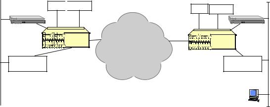
IMACS alarms are reported either to a local device or via an internal 2400 bps modem in a proprietary ASCII format to a central site. Additionally, the IMACS can be optioned to use TCP/IP and encode alarms as standard SNMP traps. One method of transmitting TCP/IP management information and SNMP traps is to activate the Serial Line Internet Protocol (SLIP) on the DB-9 port set at 9.6 Kbps. requires that a routed network exists and has full connectivity back to the location where the SNMP-based NMS resides. Figure 4 illustrates how terminal servers are used to provide connectivity from the IMACS’ serial interface to the router-based network. A typical NMS scenario is described below:
Remote Site 1
PBX 
 CODEC
CODEC
Router
IMACS |
Terminal
Server
|
Remote Site 2 |
PBX |
CODEC |
|
Router |
Frame Relay |
IMACS |
Network |
Terminal |
|
|
|
Server |
NMS
Figure 3 - IMACS Connectivity to Terminal Servers
1.An alarm occurs in the IMACS on the left side of the diagram and an SNMP trap is sent out the serial port on the interface card.
2.A serial port of a Terminal Server that is configured for SLIP or PPP accepts the SNMP trap and forwards it over the Ethernet LAN.
3.The IP destination is the NMS; where it is picked up by the router for delivery to the NMS.
4.The router forwards the trap and other traffic destined for remote LANs, via its Frame Relay WAN connection. The router is connected through the IMACS to a Frame Relay network. The Frame Relay Network delivers the SNMP trap to the Operations Center on the right side of the diagram.
5.At the Operations Center, the IMACS, acting as a DSU/CSU, delivers traffic to the router.
6.The router places the SNMP trap onto the appropriate LAN where the NMS resides.
7.The NMS acknowledges and processes the trap. At this point an operator, noticing this new alarm, could initiate a TELNET session back to the originating IMACS or could browse the MIBs from the NMS.
March 2001 |
Page 9 |

Zhone Technologies, Inc. |
IMACS Product Book, Version 4 |
As shown in Figure 4 the IMACS supports multiple methods of communicating SNMP messages and Telnet terminal sessions between an end node and the network management station. The addition of PPP support allows the IMACS to connect to routers or terminal servers to establish a connectivity path to the network management station. The utilization of PPP is similar to that of SLIP.
PSTN
T1/E1
Frame
Relay
PBX |
PPP |
Router
Figure 4 - SNMP Messages and Telnet Sessions on IMACS
IMACS Management Using FDL/SA4
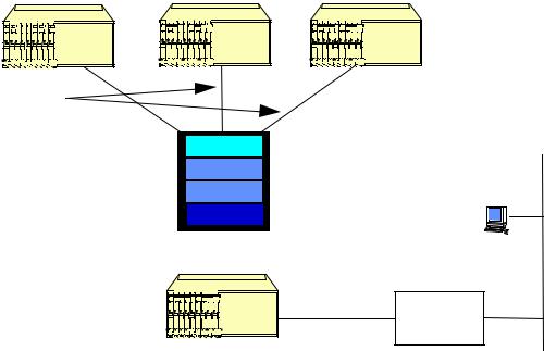
Another method of transporting IP datagrams is via the Facility Data Link (FDL) on a T1 link using the Extended Super Frame (ESF) format. The FDL channel is a 4 Kbps channel available on the DS1 frame in the ESF overhead. The SA4 bits in the frame alignment word of the E1 constitute the equivalent for E1. This method requires that a DACS II is used in the central office, and is provisioned to extract the FDL / SA4 stream from the T1 /E1 and map it into a DS0 channel. DS0 channels from each remote node are then transported to an IMACS equipped with a B7R or MCC card so that IP datagrams can be extracted.
The use of the 4 Kbps FDL to carry management information across the network is illustrated in Figure 6. The remote IMACS at the top of the figure are terminated in a DACS II. The remote IMACS transport the TCP/IP management information across the FDL. The DACS II transforms the FDL channel into a DS0 channel using its proprietary B7R encoding scheme. These DS0s, carrying management information are combined with other DS0s carrying user information and arrive at the IMACS as shown in the bottom of the figure.
March 2001 |
Page 10 |
Zhone Technologies, Inc. |
IMACS Product Book, Version 4 |
|
|
IMACS |
FDL over ESF 
IMACS |
IMACS |
DACS
Each FDL is mapped to a separate DS0
T1 |
|
NMS |
|
|
|
|
|
|
IMACS 38.4 kbps SLIP |
Terminal |
|
Server |
Concentrator Node |
|
Figure 5 - IMACS Management Using FDL
The management DS0s are connected internally to the B7R card with a limit of eight management DS0s per card. The output of the B7R card is RS-232 at up to 38.4 Kbps using SLIP. This output is fed into a terminal server or a router and transported to a NMS. Alternatively, the SLIP Async stream can be connected directly into a locally attached NMS if a port is available. Furthermore, the MCC server card supports up to 128 remote connections.
IMACS Management Using B7R encoded DS0 (TS 24 for T1 and TS 31 for E1)
A third method is to carry IP traffic in a DS1’s time slot 24 or E1’s time slot 31. This method requires that each time slot 24/31 from multiple remote nodes are groomed in the network into a single T1, and are transported to an IMACS equipped with a B7R or MCC card so that IP data can be extracted.
A B7R card or a MCC card is used in the IMACS at the central site to accept and decode SNMP network management information from up to eight remote IMACS (via separate DS0s) (128 for MCC). The IMACS at the remote sites can place SNMP traps and other IP traffic in a B7R encoded DS0 (time slot 24/31). A B7R card is not required at the remote sites. At the central site a B7R/MCC card is required only if the B7R / DS0 transport mechanism is utilized.
The TCP/IP option must be available to support the B7R function. If the SNMP traps and associated TELNET sessions are carried in a B7R encoded DS-0 from the originating IMACS (instead of within the FDL), a DACS II is not required. In this case the NMS data from the originating IMACS is formatted by the remote IMACS’s CPU in the same B7R format as would have been generated by the DACS II if the FDL scheme was used. In either case, a B7R or MCC card is required at the NMS concentrator site. The B7R card is a User card, therefore up to eight B7R cards may reside in an IMACS node, supporting eight DS0s each, for a total of 64 remote sites per IMACS. The MCC card is a server card, supporting up to 128 remote IMACS nodes. A total of 3 MCC cards are supported per concentrator node.
March 2001 |
Page 11 |
Zhone Technologies, Inc. |
IMACS Product Book, Version 4 |
|
|
To manage the IMACS containing the B7R card, a separate SLIP/PPP connection from the DB9 on the interface card is required. The local IMACS cannot route its own SNMP information to an internal B7R card. For example, if a network has eight remote nodes, two SLIP connections are required at the central site - one for the eight remote IMACS and one for the local IMACS.
The Management Channel Concentrator (MCC) card allows management of the local system as well as 128 remote IMACS nodes. The remote systems may either be communicating using B7R on TS 24 (T1) or B4R on TS31 (E1) directly, via a cross-connect or be using FDL (T1) /SA4 (E1) with a DACS version 6.2 or equivalent. In addition, the MCC card has also four ports configurable with for a variable number of nx64 kbit DS0s. These can be used to forward already concentrated IP traffic down to a second MCC card.
Any SNMP manager can receive the SNMP trap and respond by initiating a TELNET session with the originating IMACS for diagnostics and control. Note that the local and remote reporting feature of the IMACS is disabled if the TCP/IP network management feature is active. The IMACS supports sending traps up to three SNMP trap servers, allowing alarms to be sent to multiple network management stations.
However, once the cards are installed and the chassis populated, these identifiers are no longer visible.
March 2001 |
Page 12 |
Zhone Technologies, Inc. |
IMACS Product Book, Version 4 |
|
|
a) E & M card with 2713 Hz Loop back – Module# 811760:
This feature will provide digital loop back (both audio and signaling) when activated by a 2713 Hz tone of specified level and duration. The requirements are provided by BellCore PUB 42004. When a validated tone is detected the channel should disconnect the user and provide loop back of signals (audio and signaling) received from the network. The loop back must be performed without inserting any gain or loss in the path. After tone activation, the channel shall remain in the loop back mode unless deactivated for a period of 20 minutes (+/- 1 minute) after which the channel shall automatically revert to the idle (non loop back) mode.
b)(Optional) P-Phone Line card with 8 ports (PPS Module# 812160 and PPO Module# 813160):
The purpose of this feature is to provide an 8-port P-Phone Line card in the Streamline for Host 1.2. The P-Phone line card is used by Nortel to support transport of P-Phone service. There are two applications of the line card, one at the Office end (P-Phone Office – PPO), and one at the Station end (P-Phone Station – PPS). Hence, PPO and PPS are two user cards designed to support connectivity between a Nortel SL-100 PBX or DMS-100 based Centrex PBX and Nortel M5000 series Electronic Business Sets (P-Phones). The P-Phone is an electronic telephone set capable of supporting premium Meridian Digital Centrex (MDC) features offered by the local DMS switch. The data channel allows out-of-band signaling between the P-Phone and the DMS switch. This data channel allows the user to activate MDC features, such as conference calling by simply pushing keys on the P-Phone set, and for the DMS to deliver information, such as caller identification, to the P-Phone display. This P-Phone line card encodes the received out-of-band signaling tones, transports them across the carrier and decodes the digital representation back to out-of-band tones at the other end. Hence, this line card simply repeats the signaling end-to-end.
The market for P-Phones is by definition limited to Nortel switches and PBXs: DMS100 (Class 5 switch), DMS500 (Combination of Class 5 and a Tandem switch), DMS10 (Lower capacity switch for rural areas) and SL100 (Large Enterprise PBX).
P-Phones supported include: M5000 series business sets, models M5009, M5112, M5209, M5212 and M5312.
March 2001 |
Page 13 |

Zhone Technologies, Inc. |
IMACS Product Book, Version 4 |
|
|
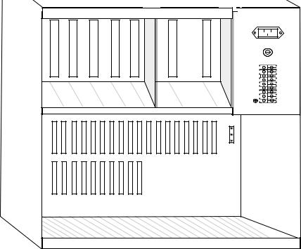
II. IMACS Chassis and Common Equipment
1. IMACS Chassis and Back Plane
The IMACS is available in three chassis models to meet various space/capacity requirements. They are the IMACS 600 Universal Enclosure, the IMACS 800 Universal Enclosure and the IMACS 900 Universal Enclosure.
IMACS 800 Universal Enclosure
The IMACS 800 Universal Enclosure provides card slots on both the front and back of the unit for both front and rear loading. These are sometimes referred to as the “Network” and “User” sides respectively. There are nine card slots that are accessible from the front and an additional nine that are accessible from the back. Card slots are intended to accommodate specific card types and are keyed so that only those card types may be inserted in those slots. A CPU card may be inserted in either Slot C1 or C2. Two CPUs can be installed in Slots C1 and C2 simultaneously to provide CPU redundancy. All IMACS Universal Enclosure models are NEBS (TR63) approved.
The nine front card slots are allocated and shown in Figure 7 as follows:
Slot Number |
|
|
|
|
|
|
|
|
|
|
|
|
|
|
|
|
|
|
|
|
Card Types Supported |
|||||||||||||||
C1 and C2 |
|
|
|
|
|
|
|
|
|
|
|
|
|
|
|
|
|
|
|
|
|
|
|
CPU cards |
||||||||||||
P1, P2 and P3 |
|
|
|
|
|
|
|
|
|
|
|
|
|
|
|
|
|
|
|
|
|
|
|
Server cards |
||||||||||||
W1, W2, W3 and W4 |
|
|
|
|
|
|
|
|
|
|
|
|
|
|
|
|
|
|
|
|
|
|
|
WAN cards |
||||||||||||
|
|
|
|
|
|
|
|
|
|
|
|
|
|
|
|
|
|
|
|
|
|
|
|
|
|
|
|
|
|
|
|
|
|
|
|
|
|
|
|
|
|
|
|
|
|
|
|
|
|
|
|
|
|
|
|
|
|
|
|
|
|
|
|
|
|
|
|
|
|
|
|
|
|
|
|
|
|
|
|
|
|
|
|
|
|
|
|
|
|
|
|
|
|
|
|
|
|
|
|
|
|
|
|
|
|
|
|
|
|
|
|
|
|
|
|
|
|
|
|
|
|
|
|
|
|
|
|
|
|
|
|
|
|
|
|
|
|
|
|
|
|
|
|
|
|
|
|
JP1
EUR/US
 1
1
 2
2  3
3
|
|
|
|
|
F1 |
F2 |
C1 C2 |
P1 P2 |
P3 W1 |
W2 |
W3 |
W4 |
|
Figure 6 - IMACS 800 Universal Enclosure—Front View
March 2001 |
Page 14 |
Zhone Technologies, Inc. |
IMACS Product Book, Version 4 |
|
|
The nine back card slots are designated as IF and U1 through U8 respectively and are allocated and shown in Figure 7 as follows:
Slot Number |
|
|
|
|
|
|
Card Types Supported |
||||||||||||||||||||||||||||||||||||||||||||
IF |
|
|
|
|
|
|
Interface card |
||||||||||||||||||||||||||||||||||||||||||||
U1 through U8 |
|
|
|
|
|
|
|
|
|
Voice, Data and External Alarm cards |
|||||||||||||||||||||||||||||||||||||||||
|
|
|
|
|
|
|
|
|
|
|
|
|
|
|
|
|
|
|
|
|
|
|
|
|
|
|
|
|
|
|
|
|
|
|
|
|
|
|
|
|
|
|
|
|
|
|
|
|
|
|
|
|
|
|
|
|
|
|
|
|
|
|
|
|
|
|
|
|
|
|
|
|
|
|
|
|
|
|
|
|
|
|
|
|
|
|
|
|
|
|
|
|
|
|
|
|
|
|
|
|
|
|
|
|
|
|
|
|
|
|
|
|
|
|
|
|
|
|
|
|
|
|
|
|
|
|
|
|
|
|
|
|
|
|
|
|
|
|
|
|
|
|
|
|
|
|
|
|
|
|
|
|
|
|
|
|
|
|
|
|
|
|
|
|
|
|
|
|
|
|
|
|
|
|
|
|
|
|
|
|
|
|
|
|
|
|
|
|
|
|
|
|
|
|
|
|
|
|
|
|
|
|
|
|
|
|
|
|
|
|
|
|
|
|
|
|
|
|
|
|
|
|
|
|
|
|
|
|
|
|
|
|
|
|
|
|
|
|
|
|
|
|
|
|
|
|
|
|
|
|
|
|
|
|
|
|
|
|
|
|
|
|
|
|
|
|
|
|
|
|
|
|
|
|
|
|
|
|
|
|
|
|
|
|
|
|
|
|
|
|
|
|
|
|
|
|
|
|
|
|
|
|
|
|
|
|
|
|
|
|
|
|
|
|
|
|
|
|
|
|
|
|
|
|
|
|
|
|
|
|
|
|
|
|
|
|
|
|
|
|
|
|
|
|
|
|
|
|
|
|
|
|
|
|
|
|
|
|
|
|
|
|
|
|
|
|
|
|
|
|
|
|
|
|
|
|
|
|
|
|
|
|
|
|
|
|
|
|
|
|
|
|
|
|
|
|
|
|
|
|
|
|
|
|
|
|
|
|
|
|
|
|
|
|
|
|
|
|
|
|
|
|
|
|
|
|
|
|
|
|
|
|
|
|
|
|
|
|
|
|
|
|
|
|
|
|
|
|
|
|
|
|
|
|
|
|
|
|
|
|
|
|
|
|
|
|
|
|
|
|
|
|
|
|
|
|
|
|
|
|
|
|
|
|
|
|
|
|
|
|
|
|
|
|
|
|
|
|
|
|
|
|
|
|
|
|
|
|
|
|
|
|
|
|
|
|
|
|
|
|
|
|
|
|
|
|
|
|
|
|
|
|
|
|
|
|
|
|
|
|
|
|
|
|
|
|
|
|
|
|
|
|
|
|
|
|
|
|
|
|
|
|
|
|
|
|
|
|
|
|
|
|
|
|
|
|
|
|
|
|
|
|
|
|
|
|
|
|
|
|
|
|
|
|
|
|
|
|
|
|
|
|
|
|
|
|
|
|
|
|
|
|
|
|
|
|
|
|
|
|
|
|
|
|
|
|
|
|
|
|
|
|
|
|
|
|
|
|
|
|
|
|
|
|
|
|
|
|
|
|
|
|
|
|
|
|
|
|
|
|
|
|
|
|
|
|
|
|
|
|
|
|
|
|
|
R1 |
R2 |
R3 |
R4 |
R5 |
|
|
|
|
|
|
|
|
|
|
|
AC |
|
|
|
|
|
|
|
|
|
|
|
|
|
|
|
|
|
|
R + - - + + - C |
|
|
|
|
|
|
|
|
||||
|
|
|
G V |
V |
A |
V |
O |
IF |
U1 |
U2 |
U3 |
U4 |
U5 U6 |
U7 |
U8 |
|
|
|
R N |
|
B |
M |
|||||||||
Figure 7 - IMACS 800 Universal Enclosure—Rear View
In addition to the card slots described above, the IMACS 800 chassis accommodates a power supply and ringing generator system. The power and ringing system can consist of up to two power supplies, two 120/240VAC-to- 48VDC Converters, and up to three ringing generators. Five ringing generators can be supported in a system if there are no 120/240VAC-to-48VDC Converters installed. The maximum power consumption of an IMACS is 125 Watts. Power supplies are inserted into either of the two power slot positions (F1 and F2) from the front of the chassis.
The IMACS 800, 900 and 600 models support load sharing power redundancy. To achieve redundancy, the installation of two identical power supplies is required. The power supply status is reported via LEDs that are visible through the front panel. Alarm messages are generated when one of the two power supplies malfunctions or fails.
IMACS 900 Universal Enclosure
The IMACS 900 Universal Enclosure has the same capacity as and provides the same module slots in a frontloading only “repackaged” version of the IMACS 800 chassis.
There are nine slots that are referred to as the “Network” cards and an additional nine (9) that are “User” cards respectively. CPU card installation and slot allocation is the same as the IMACS 800. The nine network card slots are allocated the same as the IMACS 800 and are shown in Figure 9. The nine user card slots are designated as IF and U1 through U8 respectively and are the same as the IMACS 800.
March 2001 |
Page 15 |
Zhone Technologies, Inc. |
IMACS Product Book, Version 4 |
|
|
R1 |
R2 |
|
R3 |
|
R4 |
R5 |
|
F1 |
|
|
F2 |
|
|
|
|
|
|
|
|
|
|
|
|
|
|
|
|
|
|
|
|
|
|
AC |
|
|
|
|
|
|
|
|
|
|
|
|
|
|
|
RGR |
|
|
|
|
|
|
|
|
|
|
|
|
|
|
|
|
|
VN |
+ |
|
|
|
|
|
|
|
|
|
|
|
|
|
|
|
|
- |
|
|
|
|
|
|
|
|
|
|
|
|
|
|
|
|
|
VA |
- |
|
|
|
|
|
|
|
|
|
|
|
|
|
|
|
|
+ |
|
|
|
|
|
|
|
|
|
|
|
|
|
|
|
|
|
VB |
+ |
|
|
|
|
|
|
|
|
|
|
|
|
|
|
|
|
- |
|
|
|
|
|
|
|
|
|
|
|
|
|
|
|
|
|
COM |
|
|
|
|
|
|
|
|
|
|
|
|
|
|
|
|
JP1 |
|
|
|
|
|
|
|
|
|
|
|
|
|
|
|
|
|
S |
1 |
|
|
|
|
|
|
|
|
|
|
|
|
|
|
|
|
/U |
2 |
|
|
|
|
|
|
|
|
|
|
|
|
|
|
|
|
R |
|
|
|
|
|
|
|
|
|
|
|
|
|
|
|
|
|
U |
|
|
|
|
|
|
|
|
|
|
|
|
|
|
|
|
|
E |
3 |
|
|
|
C1 |
C2 |
P1 |
P2 |
P3 |
W1 |
W2 |
W3 |
W4 |
IF |
U1 |
U2 |
U3 |
U4 |
U5 U6 |
U7 |
U8 |
|
Figure 8 - IMACS 900 Universal Enclosure
In addition to the card slots described above, the IMACS 900 chassis supports the same power supply and ringing generator system as the IMACS 800. Power supply loading is done the same way as the IMACS 800.
IMACS 600 Front Load Enclosure
The IMACS 600 Universal Enclosure provides card slots only on the front of the unit as shown in Figure 10.
This chassis is ideally suited for wall mount installations. In contrast to the IMACS 800 and 900 Enclosures (where User, CPU, WAN, and Server Cards were installed in the dedicated card slots), the IMACS 600 chassis allows user cards to be installed in any unused Server card or WAN card slot.
Slot Number |
Card Types Supported |
C1 and C2 |
CPU card |
P1-P4 |
Any Server or User card |
W1-W4 |
Any WAN or User card |
IF |
Interface card |
March 2001 |
Page 16 |

Zhone Technologies, Inc. |
IMACS Product Book, Version 4 |
|
|
|
|
|
|
|
|
|
|
|
JP1 |
|
|
|
|
|
|
|
|
|
|
|
|
|
|
|
|
|
|
S |
1 |
|
|
|
|
|
|
|
|
|
|
|
|
|
|
|
|
|
U |
|
|
|
|
|
|
|
|
|
|
|
|
|
|
|
|
|
|
/ |
2 |
|
|
|
|
|
|
|
|
|
|
|
|
|
|
|
|
|
R |
|
|
|
|
|
|
|
|
|
|
|
|
|
|
|
|
|
|
U |
3 |
|
|
|
|
|
|
|
|
|
|
|
|
|
|
|
|
|
E |
|
|
|
|
|
|
|
|
|
|
|
|
|
|
|
|
|
|
|
|
|
|
|
|
S1 |
|
S2 |
R1 |
|
|
|
|
|
|
|
|
|
|
|
R |
+ |
- |
- |
+ + |
- C |
|
|
C1 |
C2 |
P1 |
P2 |
P3 |
P4 |
W1 |
W2 |
W3 |
W4 |
IF |
G |
V |
N |
V |
A |
V |
O |
|
R |
|
|
|
B M |
|
|||||||||||||
Figure 9 - IMACS 600 Universal Enclosure
In addition to the card slots described above, the IMACS 600 Universal Enclosure accommodates two power supplies or one AC Power Supply, one AC-DC converter, and one ringing generator.
Physical and Environmental Characteristics
The IMACS Universal Enclosure dimensions are shown in Table 1.
Table 1--IMACS Dimensions
Chassis |
Height |
|
Width |
|
Depth |
|
|||
Model |
in. |
|
cm |
in |
|
cm |
in |
|
cm |
600 |
9.120 |
|
23.16 |
17.042 |
|
43.29 |
9.131 |
|
23.19 |
800 |
9.120 |
|
23.16 |
17.042 |
|
43.29 |
15.300 |
|
38.86 |
900 |
15.375 |
|
39.05 |
16.918 |
|
42.97 |
9.105 |
|
23.13 |
The IMACS 600/800/900 can be mounted on:
•EIA 19” (482 mm) standard open rack
•Enclosed Cabinet or a WECO 23” (584 mm) standard open rack
•Enclosed Cabinet (by using adapter ears)
•Wall-mounted (with 4 screws)
•Desktop
March 2001 |
Page 17 |

Zhone Technologies, Inc. |
IMACS Product Book, Version 4 |
All the IMACS units are convection-cooled and require some minimum clearances for optimum operation. Clearance requirements also account for distance required for removal and insertion of cards from/into the chassis. The minimum clearances are shown in Table 2.
Table 2—IMACS Minimum Clearances
|
|
600 |
|
800 |
|
900 |
|
|
|
|
|
|
|
Front |
15” |
(38 cm) |
15” |
(38 cm) |
15” |
(38 cm) |
Back |
0” |
(0 cm) |
15” |
(38 cm) |
0” |
(0 cm) |
Top |
2” |
(5 cm) |
2” |
(5 cm) |
2” |
(5 cm) |
Bottom |
2” |
(5 cm) |
2” |
(5 cm) |
2” |
(5 cm) |
In all cases, the unit must be installed in an environment that meets the following specifications:
AC power (120VAC): |
90 VAC to 135 VAC |
AC power (120/240 VAC): |
175 VAC to 264 VAC |
DC power (-48 VDC): |
-42 VDC to -60 VDC OR-39VDC TO -60VDC |
DC power (24 VDC): |
20 to 32 VDC OR -18VDC TO 36 VDC |
Power consumption: |
125 Watts |
Operating temperature: |
0oC to 50oC (41oF to 121oF) |
Storage temperature: |
-20oC to 80oC (-4 oF to 176oF) |
Operating Rel. Humidity: |
5% to 85% |
The IMACS Universal Enclosures conform to the following regulatory standards shown in Table 3.
Table 3—IMACS Compliance With Regulatory Standards
ANSI 310-D |
Racks, Panels, and Associated Equipment |
UL 459 |
Telephone Equipment |
Bellcore GR-63-CORE |
Network Equipment-Building System (NEBS), Level 3 |
|
Requirements: Physical Protections |
Bellcore GR-1089-CORE, Issue 1 |
Electrical compatibility and electrical safety generic criteria |
|
for network telecommunications equipment |
Bellcore TR-NWT-000295 Issue 2 |
Isolated Ground Planes: Definition and Application to |
|
Telephone Central Offices |
CE EN 500 81-1 |
Electromagnetic compatibility generic emission standard |
|
Part 1 Residential, commercial and light industry |
CE EN 500 82-1 |
Electromagnetic compatibility generic immunity standard |
|
Part 1 Residential, commercial and light industry |
CE EN 60 950/A2 |
Safety of information technology equipment including |
|
electrical business equipment |
UL 1459 |
UL Standard for Safety of Telephone Equipment |
CSA C22.2, No. 950, DOC CS03 |
Safety of information technology equipment including |
|
electrical business equipment |
FCC Part 68 – Subpart B |
Requirements for Connection of Terminal Equipment |
|
Systems and Protective Apparatus to the Telephone Network |
IEC 297-1 |
Racks, Panels, and Associated Equipment |
FCC Part 15 |
Subpart B |
Power Supplies
The IMACS has six power supplies and two ring generators, which can be installed or configured depending on the application. Power supply models 8901, 8902 and 8907 provide +/-5VDC and +/-12VDC. As shown in table 4, the main difference between these models is the input voltage.
March 2001 |
Page 18 |

Zhone Technologies, Inc. |
IMACS Product Book, Version 4 |
Models 8903, 8905 and 8908 power supplies provide -48 VDC talk battery voltage from an AC input voltage. As shown in table 4, the difference between models 8903 and 8905 is the input voltage range. Model 8905 has a much wider input voltage range. Allowing it to operate from any AC line voltage, where as model 8903 has a limited range. Model 8908 can only be used with the 900 chassis. It also has the benefit of a wide input voltage range but with the addition of providing 300 watts of talk battery power.
Table 4—Power Supply Specifications
Model 8901 AC Power Supply 120/240 AC |
|
Input Voltage |
Self-detecting, 90VAC to 135 VAC at 60HZ |
|
175 VAC to 264 VAC at 50 Hz |
Input Frequency |
47 to 63 Hz |
Inrush Surge Current |
Max. 12 amp peak at 264 VAC cold start |
Output Power |
55W Continuous |
Maximum Number per system |
2 |
Redundancy |
Optional |
Ventilation |
Convection cooled |
Protection |
Unit is fused and protected from short circuits and over- |
|
voltage |
Approvals |
UL 1459, EN 60950, CSA-C22.2 No.950, CE Mark |
Model 8902 DC Power Supply 48 VDC |
|
Input Voltage |
-39 to -60 VDC |
Inrush Surge Current |
Maximum 12 amp at 60VDC |
Output Power |
55 Watts Continuous |
Maximum Number per system |
2 |
Redundancy |
Optional |
Ventilation |
Convection cooled |
Protection |
Unit is fused protected from short circuits and overage |
|
Unit is diode protected from reversed polarity |
Approvals |
UL 1459, EN60950, CSA-C22.2 No.950, CE Mark |
Model 8907 DC Power Supply 24 VDC, |
|
Input Voltage |
18 to 36 VDC |
Inrush Surge Current |
Maximum 12 amp at 36 VDC |
Output Power: |
55 Watts Continuous |
Maximum Number per system |
2 |
Redundancy |
Optional |
Ventilation |
Convection cooled |
Protection |
Unit is fuse protected from short circuits and over-voltage |
|
Unit is diode protected from reverse polarity |
Approvals |
UL 1459, EN60950, CSA-C22.2 No.950, CE Mark |
Model 8903 Power Supply 120 VAC |
|
Input Voltage |
90VAC to 132 VAC |
Input Frequency |
60 Hz |
Inrush Surge Current |
Max. 20amp peak at 132 VAC cold start |
Output Voltage |
-48.0 VDC |
Maximum Number per system |
2 |
Redundancy |
Optional |
Ventilation |
Convection cooled |
Protection |
Unit is fused and protected from short circuits and over- |
|
voltage |
Approvals |
UL 1459, UL 1950, CSA-C22.2 No.950 |
March 2001 |
Page 19 |
Zhone Technologies, Inc. |
IMACS Product Book, Version 4 |
|
|
|
|
|
|
|
|
|
|
|
Model 8905 Power Supply, 120/240 VAC |
|
|
|
Input Voltage |
90 Vrms to 260 Vrms |
|
|
Input Frequency |
50/60 Hz |
|
|
Output Power |
100W max |
|
|
Output Voltage |
-48.0 VDC |
|
|
Output Current |
2 amp |
|
|
Maximum Number per system |
2 |
|
|
Redundancy |
Optional |
|
|
Ventilation |
Convection cooled |
|
|
Approvals |
UL 1459, UL 1950, CSA-C22.2 No.950, CE Mark |
|
|
Model 8908 Power Supply, 105/240 VAC |
|
|
|
Input Voltage |
90 Vrms to 260 Vrms |
|
|
Input Frequency |
50/60 Hz |
|
|
Output Power |
300 W max |
|
|
Output Voltage |
-48.0 VDC |
|
|
Output Current |
6.25 amp |
|
|
Maximum Number per system |
2 |
|
|
Redundancy |
Optional |
|
|
Ventilation |
Forced Air, (120mm Fan) |
|
|
Approvals |
UL 1459, UL 1950, CSA-C22.2 No.950 |
|
Ring Generator
Ring generators are required to supply ringing current whenever there are Foreign Exchange Station (FXS) Cards operating in the unit or if there is one or more Foreign Exchange Office (FXO) ports that are used in Manual Ring Down (MRD) mode.
•The current ring generator model is: Model 890620
Model 890620,the internal ring generators, will support up to 24 simultaneously ringing phones. Additional ringers can be added depending on the chassis and application, (see table 5). The exact number of simultaneously ringing subscriber lines supported is a function of the Bell Ringer Equivalency Number (REN) of the attached devices and the loop impedance. The user may attach an external ring generator to the IMACS terminal block location marked RGR.
The model 890620 is an enhanced version of the current 8906 ring generator. This model has improved operating efficiency and inrush current limiting.
Table —Ring Generator Specifications
|
|
Model 890620 Ringing Generator |
|
|
|
|
|
Input Voltage |
|
42 to 57 VDC, linear = 0.84 max. |
|
|
|
Efficiency |
|
57% at 48 V and 1 kOhm load |
|
|
|
Protection |
|
5 A slow blow fuse, primary current limiting |
|
|
|
Noise |
|
Less than 32dBrnc |
|
|
|
Output Voltage |
|
100 VDC rms default – adjustable from 60 to 105 Vrms |
|
|
|
Output Current |
|
160 mA RMS continuous, 230 mA RMS cadence |
|
|
|
Output Frequency |
|
20 Hz +/- 1 Hz |
|
|
|
Operational Modes |
|
Strap selectable: Master or Slave |
|
|
|
Maximum Number per system |
IMACS 600 |
1 |
|
|
|
|
IMACS 800 |
1 Master, 3 slaves (DC operation) |
|
|
|
|
IMACS 900 |
2 slaves (AC operation) |
|
|
|
|
1 Master, 1 slave |
||
|
|
Redundancy |
|
There is no provision for Master Ringer redundancy, however |
|
|
|
|
|
the slave units provide fail-over protection |
|
|
|
|
|
|
|
|
March 2001 |
|
Page 20 |
|
|
Zhone Technologies, Inc. |
IMACS Product Book, Version 4 |
|
|
|
|
|
|
|
|
|
|
|
Ventilation |
Convection cooled |
|
|
Approval |
UL 1459, CSA-C22.2, No. 950 |
|
March 2001 |
Page 21 |
Zhone Technologies, Inc. |
IMACS Product Book, Version 4 |
|
|
2. CPU Cards
The CPU card has two micro-controllers, which performs most of the configuration, management, and common processing for the IMACS. The CPU card provides the interconnection of WAN/User/Server TDM buses through a bus connect or cross-connect function. The CPU can have flash memory which is used to store configuration information and facilitates new firmware uploads. The IMACS can have up to 2 CPU cards, which provide redundant control and switching capabilities. If the primary CPU fails, the standby takes over.
There are two microprocessors on the CPU card. The primary micro-controller on the CPU card does the configuration and maintenance functions for the IMACS. It is connected through an internal bus to all the Server/WAN/User cards and the Interface card. It controls the modem, database, serial terminal interfaces, and Stratum 4 clock configuration contained on the Interface card. The CPU is responsible for configuring the hardware residing on the cross-connect module (CCM), and configuring hardware on WAN/User cards. It is responsible for downloading configurations onto intelligent cards through the appropriate configuration interface. Finally, it accesses each WAN card to process FDL messages. The CPU provides control functionality, however it is the Interface card that stores the system configuration information.
The second micro-controller handles standard signaling processing for voice applications. It manages both the digital (bit-robbed) and the analog (48V) signaling capabilities of the IMACS. It has enough throughput and interfaces to handle the 62 voice channels routed through the A and B buses. The CPU receives signaling from each analog voice port and in turn processes the data and generates the appropriate signaling bits over the signaling highway to the WAN cards. The WAN cards then embed the signaling bits into the T1/E1 data stream. It also processes the signaling from the T1/E1 link to the User cards. The CPU can also customize the format of the signaling bits. This is an important feature when interfacing with a variety of central office switches and PBXs.
Additionally, the CPU card has an interface to the IMACS’ time slot switching matrix. The switching matrix may either be a Bus connect (BCON) or Cross Connect (XCON). In the Bus connect configuration, the User bus ports can be connected to WAN bus ports but not the Server bus. When Cross-connect is used, all the TDM buses are brought up to the switching matrix, which is able to cross-connect time slots between the incoming and outgoing buses.
CPU cards can only be installed in the CPU slots. The shelf can be equipped with two CPUs, which form an active/standby pair. Watchdog timer circuitry on the Interface card helps monitor the active CPU and will activate the standby CPU if the active CPU fails. The active and standby CPUs communicate directly and the active can switch to standby by sending a single message. Additionally, a user can manually switch from the active to standby CPU by initiating a command from the VT-100 console. It is the CPU card, which initializes the system upon power-up and runs a self-test on all cards plugged into the system. After the initialization procedure, the CPU card continuously polls all cards in the system to determine their operating status. Table 7 provides detailed specifications on the five CPU models.
March 2001 |
Page 22 |
|
Zhone Technologies, Inc. |
|
|
|
IMACS Product Book, Version 4 |
|||
|
|
|
|
|
|
|
|
|
|
Table 7—Operational Modes |
|
|
|
|
|
|
|
|
Model |
Mode |
|
Cross Connect |
|
Drop and Insert |
Terminate |
|
|
880060 |
Bus-connect |
|
No |
|
Yes |
Yes |
|
|
880460 |
Enhanced bus- |
|
No |
|
Yes |
Yes |
|
|
|
connect |
|
|
|
|
|
|
|
880160, 880260, |
Cross-connect |
|
Yes |
|
Yes |
Yes |
|
|
880360 |
|
|
|
|
|
|
|
|
LED Indicators |
|
Green for normal operation. Amber for card fault or test mode (amber |
|||||
|
|
|
on new cards). |
|
|
|
||
|
Code Storage |
|
|
|
|
|
|
|
|
Models 880060, 880160, 880460 |
256K EPROM |
|
|
|
|||
|
Model 880260 |
|
512K EPROM |
|
|
|
||
|
Model 880360 |
|
Configurable with maximum 8MB DRAM and 4MB Flash memory |
|||||
|
Maximum number of WAN links |
|
|
|
|
|
|
|
|
Model 880060 |
|
Up to 2 WAN links |
|
|
|
||
|
Model 880160, 880260, 880360 |
Up to 8 WAN links |
|
|
|
|||
|
Model 880460 |
|
Up to 4 WAN links. WANs in slot W1 supports voice only operate in |
|||||
|
|
|
either Terminate or Drop and Insert mode. WANs in slot W3 operate |
|||||
|
|
|
in Terminate mode only and only terminate certain data ports. |
|||||
|
Support for CPU redundancy |
|
|
|
|
|
|
|
|
Model 880060 |
|
No |
|
|
|
||
|
Model 880160, 880260, 880360, |
Yes |
|
|
|
|||
|
880460 |
|
|
|
|
|
|
|
|
Support for WAN link redundancy |
|
|
|
|
|
|
|
|
Model 880060 |
|
No |
|
|
|
||
|
Model 880460 |
|
1:1—A WAN card in slot W2 provides backup for an identically |
|||||
|
|
|
configured WAN card in slot W1. A WAN card in slot W4 provides |
|||||
|
|
|
backup for an identically configured WAN card in slot W3. |
|||||
|
Model 880160, 880260, 880360 |
1:N—A single model 8014 WAN card in slot W4 provides backup for |
||||||
|
|
|
identically configured 8010 WANs in slots W1 through W3. |
|||||
|
Support for Server Cards |
|
|
|
|
|
|
|
|
Model 880060, 880460 |
No |
|
|
|
|||
|
Model 880160 |
|
Only ADPCM Server card |
|
|
|
||
|
Model 880260, 880360 |
Support for all server cards |
|
|
|
|||
|
Standards Conformance |
|
|
|
|
|
|
|
|
Bellcore GR-63-CORE |
Network Equipment-Building System (NEBS) Requirements: Physical |
||||||
|
|
|
Protections |
|
|
|
||
|
CE EN 500 81-1 |
|
Electromagnetic compatibility generic emission standard Part 1 |
|||||
|
|
|
Residential, commercial and light industry |
|
|
|||
|
CE EN 500 82-1 |
|
Electromagnetic compatibility generic immunity standard Part 1 |
|||||
|
|
|
Residential, commercial and light industry |
|
|
|||
|
CE EN 60 950/A2 |
|
Safety of information technology equipment including electrical |
|||||
|
|
|
business equipment |
|
|
|
||
|
UL 1950 |
|
UL Standard for Safety of Information Technology Equipment |
|||||
|
CSA C22.2, No. 950 |
|
Safety of information technology equipment including electrical |
|||||
|
|
|
business equipment |
|
|
|
||
March 2001 |
Page 23 |

Zhone Technologies, Inc. |
IMACS Product Book, Version 4 |
3. Interface Cards
The Interface card has common hardware, which is managed by the active CPU card. One Interface card is required per system residing in Slot IF on the IMACS chassis. It provides the physical interface to support a modem, control terminal, printer, alarm relay, and provides the connection up to 8 T1/E1 interfaces used by the WAN cards. The card also contains the clock hardware, which provides the entire back plane timing signals for the TDM buses. The Interface card also contains the configuration database of the IMACS, time of day clock function and watchdog timer.
The database resides in non-volatile SRAM, which enables it to retain its information even when the card is unplugged or the IMACS is powered down. The IMACS has software configurable settings for both the primary and secondary system-timing clocks. If the primary clock fails, the system will automatically switch to the operator defined secondary clock source. The interface card contains the Stratum 4 clock hardware for providing internal timing. Other timing options include: timing off the WAN card; timing off an installed ATM server card and timing off an installed 826070 or 826171 BRI card. It also has an option for external timing from external synchronization clocks (892260 IF card).
The Interface card may have a Modem port that is used to connect an ITU V.22 internal dial modem to a standard telephone line. This port may be used either to log into the unit from a remote VT100 terminal or to send system alarms to a remote device. The modem port presents an RJ11 female connector.
The node port on the Interface card provides the form-C contact closure and the physical interface so that the Alarm Cut-Off (ACO) alarm may activate an external alarm system. The node port presents an RJ48 female connector with an RS485 electrical interface.
The Control Terminal port is used to connect a VT100 or compatible terminal to the IMACS system for node management and control purposes. The Control Terminal port presents an RJ48 female connector with an RS232 DCE electrical interface. The port is set to VT100 mode for asynchronous operation at 9600 bps with 8 data bits, 1 stop bit, and no parity. Also, the port supports an automatic log out feature after 15 minutes of inactivity.
The Computer Port connects a local device for printing alarms or can be configured to support SLIP for transport of SNMP management information or database configuration information. IMACS Release 5.x provides support of asynchronous PPP and SLIP. The computer port presents a DB9 male connector with an RS232 electrical interface.
The Interface card also stores ISDN Call profiles and signaling translation tables. All configuration information is stored on the Interface card NVRAM for non-volatile storage of system configuration. A copy of the system configuration is stored on the Interface card can be downloaded to the Flash memory on the CPU card. There are eight Interface card Models:
1.892060 Eight port T1/E1 Interface Card, 2400bps modem
2.892160 Eight port T1/E1 Interface Card, no modem
3.892260 Eight port T1/E1 Interface Card, no modem, with external sync input
4.892360 Eight port T1/E1 Interface Card, 2400bps modem
5.892460 Eight port T1/E1 Interface Card, no modem (required for CPU 8803)
6.892560 Two port T1/E1 Interface Card, no modem or DB9 port
7.892660 Two port T1/E1 Interface Card, 2400bps modem
8.892760 Two port E1 Interface Card, no modem
The 8920 Interface Card supports eight T1 or E1 WAN links, via a 50-pin Amphenol connector. The card has a DB- 9 serial port for network management and two RJ48 jacks: one for an RS 485 node port and one for an RS-232 VT100 control terminal port. There is a RJ-11 modem port as well. It supports eight T1 or E1 WAN links. The
March 2001 |
Page 24 |

Zhone Technologies, Inc. |
IMACS Product Book, Version 4 |
892160 Interface Card is the same as the 892060 Interface card with the exception of the modem and can be used with the 880060, 880160 and 880460 CPU cards.
The 892260 Interface Card is similar to the 892460 except there is an external synchronization option, no node port and the DB-9 serial port is a DTE-male type. The external synchronization option is for support of up to 8 T1 Framed or E1 Unframed signals and this card can be used with the 880260 and 880360 CPU cards.
The 892360 Interface Card supports eight T1 or E1 WAN links, via a 50-pin AMP connector. The card has 128KB of NVRAM, a DB9 serial port for network management and three RJ48 jacks that connect to the modem, nodal port and VT-100 control terminal port.
The 892460 Interface Card supports the same functionality as the 892360 Interface card except that it has no internal modem port. It requires an 880360 CPU and 5.X.Y CPU firmware.
The 892560 Interface card supports one or two T1 or E1 WAN links via 2 RJ-48 jacks and includes a single RJ-48 jack for a VT100 control terminal. Additionally, two sets of Bantam jacks are available for monitoring each WAN. This interface card does not support WAN redundancy.
The 892660 Interface card supports one or two T1 or E1 WAN links via 2 RJ-48 jacks. The 892660 includes a single RJ-48 jack for a VT100 control terminal, an RJ11 port for an internal 2400 bps, and a DB9 port. Additionally, two sets of Bantam jacks are available for monitoring each WAN. This interface card does not support WAN redundancy.
The 892760 Interface card supports two E1 WAN links via 2 BNC connectors. The 892760 includes a single RJ-48 jack for a VT100 control terminal, an RS 485 Node Port and a DB9 port. Table 8 provides a detailed list of the Interface Cards’ specifications.
March 2001 |
Page 25 |
|
Zhone Technologies, Inc. |
|
|
|
|
|
|
IMACS Product Book, Version 4 |
|
||||
|
|
|
|
|
|
|
|
|
|
|
|||
|
Table 8—Interface Card Specifications |
|
|
|
|
|
|||||||
|
Model 892xxx Interface Cards |
|
Configuration Storage |
|
CPU Host Firmware compatible |
|
|||||||
|
Models 892060, 892160, 892560, |
32KB NVRAM |
|
|
3.x.y |
|
|
||||||
|
892660 and 892760 |
|
|
|
|
|
|
|
|
|
|||
|
Models 892260, 892261, 892360 |
128KB NVRAM |
|
|
4.x.y, 5.x.y |
|
|
||||||
|
and 892460 |
|
|
|
|
|
|
|
|
|
|
|
|
|
|
|
Interfaces |
|
|
|
|
|
|
|
|
|
|
|
Model |
|
T1/E1 |
|
Computer Port |
|
Control |
Node Port |
|
Internal |
External Sync |
|
|
|
|
|
Links |
|
(DB-9) |
|
|
Terminal |
|
|
Modem |
|
|
|
|
|
|
|
|
|
|
Interface |
|
|
|
|
|
|
|
|
|
|
|
|
|
Port |
|
|
|
|
|
|
892060 |
|
8 T1/E1 |
|
YES |
|
YES |
YES |
|
YES |
NO |
|
|
|
892160 |
|
8 T1/E1 |
|
YES |
|
YES |
YES |
|
NO |
NO |
|
|
|
892260 |
|
8 T1/E1 |
|
YES |
|
YES |
YES |
|
NO |
YES |
|
|
|
892261 |
|
8 T1/E1 |
|
YES |
|
YES |
YES |
|
NO |
YES |
|
|
|
892360 |
|
8 T1/E1 |
|
YES |
|
YES |
YES |
|
YES |
NO |
|
|
|
892460 |
|
8 T1/E1 |
|
YES |
|
YES |
YES |
|
NO |
NO |
|
|
|
892560 |
|
2 T1 |
|
NO |
|
YES |
YES |
|
NO |
NO |
|
|
|
892660 |
|
2 T1 |
|
YES |
|
YES |
NO |
|
YES |
NO |
|
|
|
892760 |
|
2 E1 |
|
YES |
|
YES |
YES |
|
NO |
NO |
|
|
|
|
|
WAN Ports |
|
|
|
|
|
|
|
|
||
|
Electrical Interface |
|
|
|
|
G.703 or DSX-1 |
|
|
|||||
|
|
|
Model |
|
|
|
|
|
Connector Type |
|
|||
|
892060, 892160, 892260, 892261, 892360 and 892460 |
One Female 50-pin RJ-27X Telco connector |
|
||||||||||
|
892560 and 892660 |
|
|
|
|
Two Female RJ-48 connector |
|
|
|||||
|
892760 |
|
|
|
|
|
|
|
Two Pair Female BNC connector |
|
|||
|
All Models prior to Rev CO |
|
|
|
|
DB9F DCE (requires 1201 cable) |
|
||||||
|
All Models from Rev CO |
|
|
|
|
DB9M DTE (requires 1202 cable) |
|
||||||
|
Electrical Interface |
|
RS-232, ITU-T V.28 |
|
|
|
|
|
|||||
|
Function |
|
|
Connects to local Element Management System |
|
|
|
|
|||||
|
Code Set |
|
|
8 bit characters plus one start and one stop bit with no parity |
|
|
|||||||
|
Max Speed |
|
|
19.2Kbps (PPP) or 9.6Kbps (SLIP) |
|
|
|
|
|||||
|
|
|
|
|
|
|
|
|
|
|
|
|
|
March 2001 |
Page 26 |
 Loading...