


 Loading...
York YPHH, YCHBC, YRHBC, YPHYB, YHBC User Manual
...
FAN COIL
AIR CONDITIONERS
INSTALLATION, OPERATION, & MAINTENANCE Supersedes: Form 115.20-NOM2 (1199) Form 115.20-NOM2 (105)
00168VIP
MODEL YHBC – Ceiling Concealed Model
00170VIP
MODEL YHH – Ceiling Concealed Model with Electric Heat
00171VIP
MODEL YPHBC – Ceiling Concealed Model with Insulated Return. Plenum and Filter
MODEL YPHH – Ceiling Concealed Model with Electric Heat, Insulated Return Plenum and Filter
00172VIP
MODEL YCHBC – Ceiling Cabinet Model
00173VIP
MODEL YRHBC – Telescoping / Recessed Ceiling Model
00174VIP
MODEL YHYB – High Capacity Ceiling Concealed Model
00175VIP
|
MODEL YPHYB – High Capacity Ceiling Concealed Model |
Notes: |
with Insulated Return Plenum and Filter |
|
1.2-Pipe units have one water coil. 4-Pipe units have two water coils.
2.Changeover is used to select heating or cooling mode.
3.YORK International does not recommend “fan cycle” applications for cooling on unit mounted thermostats.
4.For proper operation, control valve must be normally closed.
5.Aquastats provided where required.
6.Electric Heat is only available in the YHH and YPHH units. These units require a remote thermostat (low voltage 4 wire thermostat).
***** WARNING TO INSTALLER, SERVICE PERSONNEL AND OWNER *****
Altering the product or replacing parts with non authorized factory parts voids all warranty or implied warranty and may result in adverse operational performance and/or a possible hazardous safety condition to service personnel and occupants. Company employees and/or contractors are not authorized to waive this warning.
L23952Y 1-05

|
FORM 115.20-NOM2 (105) |
|
TABLE OF CONTENTS |
RECEIVING.......................................................................................................................................................... |
3 |
STORAGE............................................................................................................................................................ |
3 |
PREPARE CEILING FOR MOUNTING................................................................................................................ |
3 |
WIRING............................................................................................................................................................... |
3 |
PIPING ................................................................................................................................................................. |
6 |
DRAIN PIPING..................................................................................................................................................... |
7 |
DRAWINGS................................................................................................................................................... |
8 - 14 |
STARTUP........................................................................................................................................................... |
15 |
MAINTENANCE................................................................................................................................................. |
16 |
Reference Documents:
• IOM for YVC-YVF-YVS |
Form 115.20-NOM3 (Latest) |
• IOM for YSHW, YSHX |
Form115.22-NOM5 (Latest) |
• IOM for YSVW, YSVX |
Form 115.22-NOM2(Latest) |
• Parts List |
Form 115.20-RP2(Latest) |
These documents can be ordered through Publications Dept.
or downloaded @ http://intranet.york.com/web0003/library/default.asp
|
|
NOTE: |
|
|
Use direction of airflow |
|
|
|
for selecting rightand |
|
|
|
left-hand units. |
|
|
TABLE 1 - NOMINAL AIRFLOWS |
|
||
|
|
|
|
UNIT SIZE |
CFM |
|
|
3 |
300 |
|
|
4 |
400 |
|
|
5 |
500 |
|
|
6 |
600 |
|
|
8 |
800 |
|
|
10 |
1000 |
|
PLENUM |
12 |
1200 |
|
|
|
(OPTIONAL) |
||
13 |
1300 |
|
|
16 |
1600 |
|
|
20 |
2000 |
|
FIG. 1 – DETERMINATION OF RIGHT-HAND / |
|
|
|
|
|
|
|
LEFT-HAND REFERENCES |
2 |
YORK INTERNATIONAL |
FORM 115.20-NOM2 (105)
INSTALLATION
RECEIVING
Material in this shipment has been inspected at the factory and released to the transportation agency in good condition. When received, a visual inspection of all cartons should be made immediately.Any evidence of rough handling or apparent damage should be noted on the delivery receipt and the material inspected in the presence of the carrier's representative.
If damage is found, a claim should be filed against the carrier immediately.
STORAGE
Iftheequipmentisnottobeimmediatelyinstalled,store it in a dry location with the motor protected against moisture, dust, corrosion and physical damage.
PREPARE CEILING FOR MOUNTING
Depending upon building construction, provisions for mounting the unit must be made by the contractor according to architects; drawings.
It is important to ensure that the fan coils are securely mounted and the structure is sufficient to support the weight of the equipment.All anchors for mounting the equipment must be placed and sized to ensure a safe and durable installation.
The YHBC, YPHBC, YRHBC, YHH, YHHS, YPHH, YHYB, andYPHYB units are designed for installation in a horizontal position above a dropped ceiling. The YCHBC is a cabinet unit intended for horizontal exposed surface mounting.
In free (non-ducted return air) return installations of YHBC, YHH, YHHS and YHYB units; the furred down area must be completely sealed (except return air grille) to ensure that all return air is pulled from the conditioned space and not from other areas of the building structure.
Access must be provided for servicing the unit. If this access is provided by a removable ceiling panel, amplespacemustbeallowedforremovaloftheblower panel and to provide access to electrical and plumbing controls.
Unit must not be operated during building construction due to excessive airborne dust and debris. The units must not be operated under any circumstances without an air filter in place.
WIRING
Allwiringmustcomplywiththelocalandnationalcode requirements. Units are provided with wiring diagrams and nameplate data to provide information required for necessary field wiring.
For power wiring a 4 x 4 electrical box is provided on thecabinetforconnectionofpowersupplyandislocated on the same side as piping.
On YHBC units, the box is shipped unattached, it is field attached to the unit in a location convenient to electrical entrance.
Any devices such as fan switches or thermostats that have been furnished by the factory for field installation must be wired in strict accordance with the wiring diagram that is supplied with the unit. Failure to do so could result in damage or injury.
YORK INTERNATIONAL |
3 |
FORM 115.20-NOM2 (105)
INSTALLATION
|
|
|
|
|
|
|
|
|
|
|
|
|
|
|
|
|
|
|
|
|
|
|
|
|
|
|
|
|
|
|
|
|
|
|
|
|
|
||
|
|
|
|
|
������ |
|
|
|
|||
|
|
|
|
|
|
|
|
|
|
|
|
|
|
|
|
|
|
|
|
|
|
|
|
|
|
|
|
|
|
|
|
|
|
|
|
��� ��� ��� ��� ��� ��� ��� |
��� ��� ��� |
|
|
|
|
|
|
|
|
|
|
|
|
|
|
|
LD010198 |
|
|
|
|
|
|
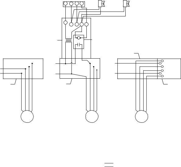
FIG. 2 – HORIZONTAL UNITS - TYPICAL WIRING
4 |
YORK INTERNATIONAL |
FORM 115.20-NOM2 (105)
INSTALLATION
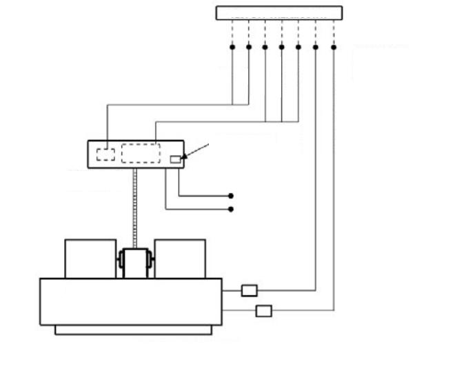
T334 THERMOSTAT
Heat-Off Cool, Fan Auto-On, 24V, Manual changeover, 4-Wire Thermostat (R, G, Y, W) Adj. Heat Anticipator, Fixed Cooling Anticipator, Fan Cycling (Cooling) or (Heating/Cooling), No Heating Required.
T404 THERMOSTAT
Heat-Off Cool, Fan Auto-On, 24V, Manual changeover, 6-Wire Thermostat (R, G, O, Y, W, B) Adj. Heat / Fixed Cool Anticipator, Fixed Cooling Anticipator, Fan Cycling.
(O & B can be used for cool and heat relays respectively, or for cool & heat water valves.)
T200 THERMOSTAT OPTION (W/CONTROLLER)
Heat-Off Cool, Fan -On, 24V, Manual changeover, 7-Wire Thermostat (R, C, Hi, Med, Lo, 24V Heat, 24V Coil), Auto fan speed control, digital readout, auto-overide.
|
|
|
|
|
|
|
|
|
|
|
|
|
|
LD010200
FIG. 3 – WIRING SCHEMATIC FOR HBC/PHBC/CHBC/RHBC/HYB/PHYB
YORK INTERNATIONAL |
5 |
Loading...