


J
SPLIT-SYSTEM HEAT PUMPS
OUTDOOR UNITS
|
INSTALLATION MANUAL |
3 , 4 ( ( " % 4 |
035-15410-002-B-0404 |
MODELS E3FB090 & E2FB120
(50 and 60 Hz)
GENERAL
! ""
#
$
#
% &
%
REFERENCE
'
' ( ( )" %
! * +
,
Standard Register
TOLL FREE Telephone: 877-318-9675
TOLL FREE Fax: 877-379-7920
- , )
.%/-) 0%!)-)1 )
.
0
& #
INSPECTION
%
- $
2 %
2
3 ' ( )+
CAUTION
WARNING

TABLE OF CONTENTS
|
|
|
|
|
|
|
|
|
|
|
|
|
INSTALLATION |
|
|
|
|
|
|
|
''5 '+ '( '%" |
|
|
!'/%) $6$, '( '%" |
|
|
|
|
|
|
|
|
|
|
|
7 8 '% %,-9 |
|
|
|
|
|
':$! ! %; |
|
|
'%#!', ! %; |
|
|
!$ < %; |
|
|
|
|
|
$%$!&, / )$, %$" |
|
|
%$ < %; |
= |
|
$!6 ($ 0&,6$" |
1 |
|
> 0 |
1 |
|
|
1 |
|
0 |
|
|
|
|
|
START-UP
7 8 '% % # %,-9
7
@ 0
MAINTENANCE
|
|
|
|||
|
|
||||
|
|
||||
|
|
||||
|
|
|
LIST OF FIGURES |
|
|
;/!$ |
|
|
|
||
|
' |
|
$"(! +# '% |
|
&;$ |
|
|
$%#$! '5 !&6 #- |
|
||
|
|
-+ (&, ;; %; |
|
||
|
|
-+ (&, $,) ! %; |
|
||
|
|
% # .$%" '%" A ,$&!&%($" |
3 |
||
|
|
$,) + %; &;!&." 8$5! ;$!&%# ,':9 |
= |
||
3B#$%) %; *$ $!6 ($ '!#"
=$5! ;$!&%# ,': &;!&.
1*&!; %; /!6$
|
*&!; %; /!6$ |
|
OPERATION |
|
|
|
|
LIST OF TABLES |
|
|
|
|
&4,$ |
|
|
|
|
||
|
|
|
|
|
|
|
||
|
|
|
|
' |
|
$"(! +# '% |
|
&;$ |
|
|
|
|
|
|
% # ++, ( '% & |
|
|
|
|
|
|
|
|
*-" (&, & |
|
|
? |
|
|
|
|
,$(#! (&, & |
|
||
'', %; +$! '% |
|
|
|
|
C/ ) %$" |
= |
||
$ %; +$! '% |
|
|
|
|
0&+'! %$" |
1 |
||
$5!'"# -(,$ |
|
3 |
|
$5! ;$!&%# %$ *&!;$ |
1 |
|||
+$! '% $,': ° |
|
|
|
|
|
|
|
|
.$!;$%(- $ +$! '% |
|
|
|
|
|
|
|
|
|
|
|
|
|
|
|
|
|
|
|
|
|
|
|
|
|
|
|
|
|
|
||||||||||||||
|
|
|
|
|
|
|
|
|
|
|
|
|
|
|
|
|
|
|
|
|
|
|
|
|
|
|
|
|
|
|
|
|
|
|
|
|
|
|
|
|
|
|
|
|
|
|
|
|
|
|
|
|
|
|
|
|
|
|
|
|
|
|
|
|
|
|
|
|
|
|
|
|
|
|
|
|
|
|
|
|
|
|
|
|
|
|
|
|
|
|
|
|
|
|
|
|
|
|
|
|
|
||||||
|
|
|
|
|
|
|
|
|
|
|
|
|
|
|
|
|
|
|
|
|
|
|
|
|
|
|
|
|
|
|
|
|
|||
|
|
|
|
|
|
|
|
|
|
|
|
|
|
|
|
|
|
|
|
|
|
|
|
|
|
|
|
|
|||||||
+, #-"#$. $ /.+ |
|
|
|
|
|
|
|
|
|
|
|
|
|
|
|
|
|
|
|
|
|
|
|
|
|
|
|
|
|
0 |
|
||||
|
|
|
|
|
|
|
|
|
|
|
|
|
|
|
|
|
|
|
|
|
|
|
|
|
|||||||||||
|
|
|
|
|
|
|
|
|
|
|
|
|
|
|
|
|
|
|
|
|
|
|
|
|
|
|
|
|
|
|
|||||
|
|
/#)''! |
% # |
|
|
|
|
|
|
|
|
|
|
|
|
|
|
|
|
|
|
|
|
|
|
|
12 3 |
|
|||||||
|
|
|
|
|
|
|
|
|
|
|
|
|
|
|
|
|
|
|
|
|
|
|
|
|
|
|
|
|
|
|
|
|
|
|
|
|
|
|
|
|
|
|
|
|
|
|
|
|
|
|
|
|
|
|
|
|
|
|
|
|
|
|
|
|
|
|
|
|
|
3 3 3 |
|
|
|
|
|
|
|
|
|
|
|
|
|
|
|
|
|
|
|
|
|
|
|
|
|
|
|
|
|
|
|
|
|
|
|
1 2 |
|
|
|
|
|
|
|
|
|
|
|
|
|
|
|
|
|
|
|
|
|
|
|
|
|
|
|
|
|
||||||||
|
|
|
|
|
|
|
|
|
|
|
|
|
|
|
|
|
|
|
|
|
|
|
|
|
|
|
|
|
|
|
|
||||
|
|
!"# $%$! '% |
|
|
|
|
|
|
|
|
|
|
|
|
|
|
|
|
|
|
|
|
|
|
|
|
|
|
|
|
|
|
|||
|
|
$('%) $%$! '% |
|
|
|
|
|
|
|
|
|
|
|
|
|
|
|
|
|
|
|
|
|
|
|
||||||||||
|
|
* !) $%$! '% |
|
|
|
|
|
|
|
|
|
|
|
|
|
|
|
|
|
|
|
|
|
|
|
|
|
|
|
||||||
|
|
|
|
|
|
|
|
|
|
|
|
|
|
|
|
|
|
|
|
|
|
|
|
|
|
|
|||||||||
|
|
|
|
|
|
|
|
|
|
|
|
|
|
|
|
|
|
|
|
|
|
|
|
|
|
|
|
|
|
'# ++, (&4,$ |
|||||
|
|
|
|
|
|
|
|
|
|
|
|
|
|
|
|
|
|
|
|
|
|
|
|
|
|
|
|
|
|
|
|
|
|
||
|
|
|
|
|
|
|
|
|
|
|
|
|
|
|
|
|
|
|
|
|
|
|
|
|
|
|
|||||||||
|
|
|
|
|
|
|
|
|
|
|
|
|
|
|
|
||||||||||||||||||||
|
|
|
|
|
|
|
|
|
|
|
|
|
|
|
|
|
|
||||||||||||||||||
|
|
|
|
|
|
|
|
|
|
|
|
|
|
|
|
|
|
|
|
|
|
|
|
|
|
|
|
|
|
||||||
|
|
|
|
|
/#)''! |
% # |
|
|
|
|
|
|
|
|
|
|
|
|
|
||||||||||||||||
|
|
|
|
|
|
|
|
|
|
|
|
|
|
|
|
|
|
|
|
|
|
|
|||||||||||||
|
|
|
|
|
|
|
|
|
090 = 7-1/2 Ton |
|
|
|
|
|
|
|
|||||||||||||||||||
|
|
|
|
|
|
|
|
|
|
|
|
|
|
|
|
|
|
|
|
|
|
|
|
|
|
|
|
|
|||||||
|
|
|
|
|
|
|
|
|
|
|
|
|
|
|
|
|
|
|
|
|
|
|
|
|
|
|
|
|
|||||||
|
|
|
|
|
|
|
|
|
|
|
|
|
|
|
|
|
|
|
|
|
|
120 = 10 Ton |
|
|
|
|
|
|
|
||||||
|
|
|
|
|
|
|
|
|
|
|
|
|
|
|
|
|
|
|
|
|
|
|
|
|
|
|
|
|
|
|
|
|
|
|
|
2 |
Unitary Products Group |

035-15410-002-B-0404
INSTALLATION
LIMITATIONS
-
3 (
/ ) 3 . 3-
2
# 2 $
TABLE 1
|
|
0',#&;$ 0&! '% 8 %2 &B 9 |
|||
12 3 |
|
1=2 |
|||
|
3 3 |
|
2 |
||
1 2 |
|
2 3 |
|||
|
! $.+$!/!$ '% (' , ° |
||||
|
% ./. |
|
&B ./. |
||
'', |
|
$ |
'', |
|
$ |
)4 |
|
)4 |
)4 |
|
= )4 |
|
! $.+$!/!$ '% (' , ° |
||||
|
% ./. |
|
&B ./. |
||
'', |
|
$ |
'', |
|
$ |
=:4 |
|
)4 |
= :4 |
|
1 )4 |
&B ./. %$ $%;#*" 5#
1 Rated in accordance with ARI Standard 110, utilization range “A”.
2Below 0°F, the control system stops the compressor and allows the electric heat accessory to cycle at its standby capacity.
3Operation below this temperature is permissible for a short period of time when a unit is required to heat the conditioned space up to 50°F.
LOCATION
/
1.The outdoor units must be installed outside the building. The outdoor fans are the propeller type and are not suitable for use with duct work.
2.The outdoor and indoor units should be installed as close together as possible and with a minimum number of bends in the refrigerant piping. Refer to REFRIGERANT PIPING for additional information.
3.The outdoor unit should not be installed beneath windows or between structures where normal operating sounds may be objectionable.
WARNING: The outdoor unit should not be installed in an area where mud and/or ice could cause personal injury. Remember that condensate will drip from the underside of the unit coils during heat and defrost cycles and that this condensate will freeze when the
temperature of the outdoor air is below 32 F.
4.All units require certain clearances for proper operation and service. Refer to General Installation Form 55.70-N1 for additional guidelines.
ROOF-TOP LOCATIONS
5 .
.
% 6"7
, 6(7 5
Unitary Products Group
& 6"7 $
647 5
! ' ( "
'
NOTE:
GROUND LEVEL LOCATIONS
%
% $
, 6(7 $ 6"7
2 647
! ' ( "
CAUTION: Care should be taken to protect the unit from tampering and unauthorized persons from injury. Screws on access panels will prevent casual tampering. Additional safety precautions such as fences around the unit or locking devices on the panels may be advisable. Check local authorities for safety regulations.
> |
|
0 |
7 |
|
8 |
|
9 |
|
|
|
|
|
|
|
|
|
|
|
|
|
|
|
|
|
|
|
|
|
|
|
|
||
|
|
|
|
|
|
|
|
|
|
|||
|
|
|
|
|
|
|
|
|
|
|
||
|
|
|
|
|
|
|
|
|
||||
|
|
|
|
|
|
|
|
|
|
|||
|
|
|
|
|
|
|
|
|
|
|
||
|
|
|
|
|
|
|
|
|
|
|
|
|
|
|
|
|
|
|
|
|
|
|
|
||
% # |
|
|
|
|
|
. 8 % 9 |
|
|
|
|||
|
|
|
|
|
|
|
|
|
|
|
||
|
|
|
|
|
|
|
|
|||||
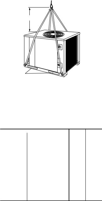
= 2 '% |
|
|
2 |
|
2 |
|
|
2 |
|
|
2 |
|
'% |
|
|
= 21 |
|
|
|
|
2 |
|
|
21 |
|
FIG. 1 - CENTER OF GRAVITY
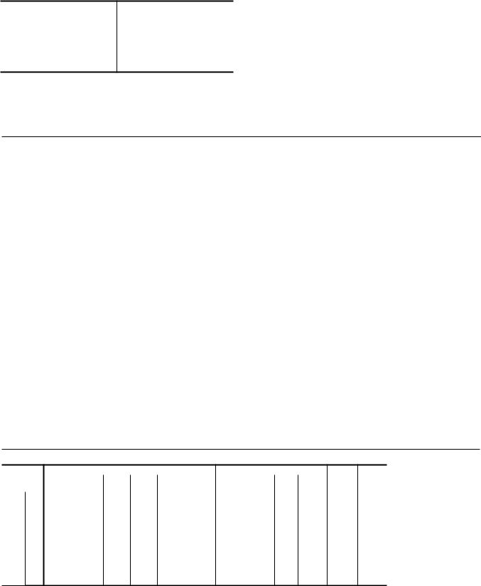
RIGGING AND HANDLING
$ 8
!
3 $
3 ' "
WARNING: Do not use straps under the unit or through the fork lift slots for lifting purposes. Sharp metal edges can damage the straps and could result in personal injury or equipment damage.
5 ' ! 9-'-)1 % /)- +%: 3/! ;% -3 0-1; -3 8-3 !-5/ 8 </%99= ) ; 3 !%*3 3 ;% - 0-99 9-' > )9=
3
/ 3
? (#"
9; !;
9 )1 ; ' ' !:3 +/3 5 % +-)-+/+ ' "@ 6 ? (#"
7 +-)-+/+ ' @ 6 ( 7
!
%
5FT.MIN.
7
FIG. 2 - TYPICAL RIGGING
CLEARANCES
%
! '
WARNING: Do not permit overhanging structures or shrubs to obstruct air discharge.
%
$
TABLE 2 - PHYSICAL DATA
|
|
|
|
|
Compressor1 |
Rating, (Tons) |
= 2 |
|
|
|
Quantity |
|
|
|
Fans |
Diameter, (In.)/No. Blades |
2 |
2 |
|
|
Nominal CFM |
3 |
=3 |
|
Fan Motors2 |
HP |
2 |
2 |
|
RPM |
|
|
||
|
||||
|
Face Area, (Sq. Ft.) |
1 = |
|
|
|
Rows Deep x Rows High |
B |
B 3 |
|
Coil |
Finned Length, (In.) |
|
3 |
|
|
Tube (Copper) OD - inches |
21 |
21 |
|
|
Fins (Aluminum) per inch |
1 |
3 |
|
Refrigerant-22 |
Holding Charge |
|
|
|
Operating Charge 3 |
|
|
||
(Lbs.) |
|
|
|
|
Pumpdown Capacity 4 |
3 |
3 |
||
|
||||
Unit Weight |
Shipping |
|
|
|
(Lbs.) |
Operating |
|
|
1These compressors are fully hermetic.
2These PSC motors are directly connected to the outdoor fans and have inherent protection, ball bearings and a 48 frame. Rotation (when viewing the shaft end of the motor) - 090=CW, 120=CCW.
3Includes outdoor unit and matched indoor blower unit, but no piping. Refer to Table 6 for refrigerant line charge.
4Based on a 95°F ambient.
4
COMPRESSORS
/ &
CAUTION: Do Not loosen compressor mounting bolts.
COMPRESSOR CRANKCASE HEATER
$
A ''B
CAUTION: Do not attempt to start the compressor without at least eight hours of crankcase heat or compressor damage will occur.
If a unit has just been installed or the unit disconnect switch has been open for a long period of time, move the system switch on the room thermostat to the “OFF” position before closing the unit disconnect switch. Eight hours of crankcase heat are required to drive the liquid refrigerant out of the compressor before the compressor can be started.
POWER AND CONTROL WIRING
- )
. 6)'*% 3 ) ? 7 #
POWER WIRING
.
.
4
NOTE:
! '
The field-supplied disconnect switch must be suitable for an outdoor location. Although it should be installed near the unit, do NOT secure it to the unit cabinet.
Refer to Figure 3 for typical field wiring.
CONTROL WIRING
Refer to Figure 4 for the location of the control wire access opening through the front of the unit.
!
( 5 $
! ' 4
$
8
#
.
Unitary Products Group
035-15410-002-B-0404
3
#
|
> |
D |
E |
F ', ) |
|
F 1 ', ) |
= |
F 1 #!&%)$) |
1 |
F 3 #!&%)$) |
= |
F #!&%)$) |
|
F #!&%)$) |
= |
*To determine the total circuit length, add the following distances:
1 |
- Outdoor Unit to Indoor Unit................................ |
____________ |
2 |
- Indoor Unit to Thermostat................................... |
____________ |
3 |
- Thermostat to Indoor Unit................................... |
____________ |
2 |
- Indoor Unit to Outdoor Unit................................. |
____________ |
|
Total Circuit Length............ |
____________ |
Both the manual and auto changeover thermostats have nonadjustable, voltage-type anticipators for both cooling and heating.
WIRE SIZING
! -
$
REFRIGERANT PIPING
GENERAL GUIDELINES
+
! 4C (444 4
FIG. 3 - TYPICAL FIELD WIRING
TABLE 3
')$, |
|
'.+!$""'! |
|
/#)''! &% '#'! |
|
% |
&B |
||
':$! |
|
':$! |
':$! |
|
|
!(/ # |
/"$ |
||
|
|
?#- |
|||||||
/++,- |
&(#'! |
/++,- |
8 &(*9 |
.+" |
<$ |
||||
|
|
|
|||||||
|
|
200/230-3-60 |
3 |
1 |
0.94 @ 208V |
208/230-1-60 |
|
|
|
3 |
|
|
0.84 @ 230V |
||||||||||
|
|
|
|
|
|
|
|
|
|||
3 460-3-60 |
|
|
0.86 |
460-1-60 |
|
3 |
1 |
|
|||
|
|
308/415-3-50 |
|
1 |
0.86 @ 380V |
380/415-1-50 |
|
3 |
1 |
|
|
|
|||||||||||
|
0.79 @ 415V |
||||||||||
|
|
|
|
|
|
|
|
|
|
||
|
|
208/230-3-60 |
|
|
0.91 @ 208V |
208/230-1-60 |
|
= |
1 |
= |
|
|
0.82 @ 230V |
||||||||||
|
|
|
|
|
|
|
|
|
|||
3 460-3-60 |
|
|
0.82 |
460-1-60 |
|
3 |
= |
|
|||
|
|
380/415-3-50 |
3 |
1 |
0.87 @ 380V |
380/415-/-50 |
|
3 |
|
|
|
|
|||||||||||
|
0.80 @ 415V |
||||||||||
|
|
|
|
|
|
|
|
|
|
||
1Based on three, 60°C insulated copper conductors in steel conduit. 2Based on a 3% voltage drop.
Unitary Products Group |
5 |
 Loading...