


J |
SUNLINE 2000 |
|
|
ELECTRIC / ELECTRIC & GAS / ELECTRIC |
|
|
SINGLE PACKAGE AIR CONDITIONERS |
|
|
(Constant Air Volume) |
|
INSTALLATION INSTRUCTION |
Supersedes: 530.18-N11Y (195) |
530.18-N11Y (399) |
|
MODELS D2CE & D2CG300 |
035-16133 |
|
(8.5 EER) |
|
208/230/460 |
208/230/575 |
|
VOLT ONLY |
||
VOLT ONLY |
||
|
DCG MODEL
SHOWN
SAFETY CONSIDERATIONS
Due to system pressure, moving parts and electrical components, installation and servicing of air conditioning equipment can be hazardous. Only qualified, trained, service personnel should install, repair, maintain or service this equipment.
‘YORK Model DCE and DCG units are single package air conditioners designed for outdoor installation on a rooftop or a slab and is manufactured under ISO 9002 Quality System Certification. The DCE models are cooling only and can be equipped with factory installed electric heaters for cooling / heating applications. The DCG models are gas-fired central heating furnaces with cooling.
The units are completely assembled on rigid, permanently attached base rails.All piping, refrigerant charge, and electrical wiring is factory installed and tested.All units require electric power, duct connections and fixed outdoor air intake damper (units without economizer or motorized damper option only) at the point of installation.
The DCG units additionally require gas connection, installation of the combustion air inlet hood and the flue gas outlet hoods at the point of installation. The gas-fired heaters have aluminized-steel tubular heat exchangers and spark ignition with proven pilot.
Supplemental electric heaters for DCE units have nickel-chrome elements and utilize single point power connections.
The following safety precautions apply to DCG units:
FOR YOUR SAFETY
If you smell gas:
1.Open windows.
2.Don’t touch electrical switches; do not use any phones in the area of the gas leak.
3.Extinguish any open flame.
4.Immediately call your gas supplier from another
location. Follow your gas supplier’s instructions.
5. If you cannot reach your gas supplier, call the fire department.
FOR YOUR SAFETY
Do not store or use gasoline or other flammable vapors and liquids in the vicinity of this or any other appliance.
INSPECTION
As soon as a unit is received, it should be inspected for possible damage during transit. If damage is evident, the extent of the damage should be noted on the carrier’s freight bill. A separate request for inspection by the carrier’s agent should be made in writing. Refer to Form 50.15-NM for additional information.
REFERENCE
Additional information on the design, installation, operation and service of this equipment is available in the following reference forms:
•44-320-10 - Barometric Relief Damper Accessory
•530.18-N6.1V - Propane Conversion Accessory
•530.18-N6.2V - High Altitude Accessory (Nat. Gas)
•530.18-N6.3V - High Altitude Accessory (Propane)
•530.18-n13y - Coil Guard Installation
Renewal Parts:
•Refer to the Renewal Parts Manual for complete listing of replacement parts on this equipment.
All forms referenced in this instruction may be ordered from:
Publications Distribution Center
Unitary Products Group
P.O. Box 1592, York, Pa. 17405
APPROVALS
Design certified by ETL & CGA as follows:
1.For use as a central cooling only unit with or without supplemental electric heat. (DCE models)
2.For use as a forced air furnace with cooling unit.(DCG models)
3.For use with natural gas or propane gas. (DCG models)
4.For outdoor installation only.
5.For installation on combustible material.
CAUTION
THIS PRODUCT MUST BE INSTALLED IN STRICT COMPLIANCE WITH THE ENCLOSED INSTALLATION INSTRUCTIONS AND ANY APPLICABLE LOCAL, STATE, AND NATIONAL CODES INCLUDING, BUT NOTLIMITEDTO, BUILDING, ELECTRICAL, AND MECHANICALCODES.
WARNING
INCORRECT INSTALLATION MAY CREATE A CONDITION WHERE THE OPERATION OF THE PRODUCT COULD CAUSE PERSONAL INJURY OR PROPERTY DAMAGE
Installer should pay particular attention to the words: NOTE, CAUTION and WARNING. Notes are intended to clarify or make the installation easier. Cautions are given to prevent equipment damage. Warnings are given to alert installer that personal injury and/or equipment damage may result if installation procedure is not handled properly.
530.18-N11Y
TABLE OF CONTENTS
General ................................................................................ |
1 |
Inspection............................................................................. |
1 |
Reference............................................................................. |
1 |
Approvals ............................................................................. |
1 |
Nomenclature....................................................................... |
2 |
INSTALLATION |
|
Limitations............................................................................ |
3 |
Location ............................................................................... |
3 |
Rigging and Handling .......................................................... |
3 |
Clearances........................................................................... |
3 |
Ductwork .............................................................................. |
3 |
Fixed Outdoor Air Intake Damper ........................................ |
4 |
Condensate Drain ................................................................ |
4 |
Compressors........................................................................ |
4 |
Filters ................................................................................... |
4 |
Service Access .................................................................... |
4 |
Thermostat........................................................................... |
5 |
Power and Control Wiring .................................................... |
5 |
Optional Electric Heaters (DCE Models) ............................. |
5 |
Combustion Discharge (DCG Models) ................................ |
5 |
Gas Piping (DCG Models) ................................................... |
6 |
Gas Connection (DCG Models)........................................... |
6 |
L.P. Units, Tanks and Piping (DCG Models)......................... |
6 |
Vent and Combustion Air Hoods (DCG Models) ................. |
7 |
Econ. / Mot. Damper Rain Hood Accy. (1EH0401) .............. |
7 |
Econ. / Power Rain Hood Accy. (1EH0402) ......................... |
9 |
OPERATION |
|
Cooling System.................................................................. |
15 |
Preliminary Operation Cooling........................................... |
15 |
Cooling Sequence of Operation......................................... |
15 |
Safety Controls (Cooling)................................................... |
15 |
Electric Heating - Sequence of Operation ......................... |
15 |
Heating Anticipator Setpoints ............................................ |
16 |
Gas Heating - Sequence of Operation .............................. |
16 |
Safety Controls (Heating)................................................... |
16 |
Heat Anticipator Setpoints ................................................. |
17 |
Pre-Start Check List........................................................... |
17 |
START-UP |
|
Operating Instructions........................................................ |
17 |
Post-Start Check List ......................................................... |
17 |
Manifold Gas Pressure Adjustment ................................... |
17 |
Pilot Checkout .................................................................... |
18 |
Burner Instructions............................................................. |
18 |
Burner Air Shutter Adjustment........................................... |
18 |
Checking Supply Air CFM.................................................. |
18 |
Adjustment of Temperature Rise........................................ |
19 |
Checking Gas Input ........................................................... |
19 |
Secure Owner’s Approval .................................................. |
19 |
MAINTENANCE & TROUBLESHOOTING
Normal Maintenance ......................................................... |
|
20 |
|
Cleaning Flue Passages and Heating Elements ............... |
20 |
||
Troubleshooting.................................................................. |
|
21 |
|
Replacement Parts ............................................................ |
|
23 |
|
|
TABLES |
|
|
No. |
Description |
Page |
|
1 |
Unit Application Data .................................. |
3 |
|
2 |
Gas Heat Application Data ......................... |
6 |
|
3 |
Pipe Sizing .................................................. |
|
6 |
4 |
Physical Data .............................................. |
|
10 |
5 |
Electrical Data |
- Basic Units ...................... |
10 |
6 |
Electrical Data |
- Units With Elec. Heat ...... |
10 |
7 |
Four and Six Point Loads............................ |
13 |
|
8 |
Supply Air Blower Performance ................. |
13 |
|
9 |
Static Resistances ...................................... |
14 |
|
10 |
Power Exhaust Performance ...................... |
14 |
|
11 |
Blower Motor and Drive Data...................... |
14 |
|
12 |
Heat Anticipator Setpoint ............................ |
16 |
|
13 |
Limit Control Setting ................................... |
17 |
|
14 |
Gas Rate - Cubic Feet Per Hour................. |
19 |
|
|
FIGURES |
|
|
No. |
Description |
Page |
|
1 |
Typical Rigging............................................ |
|
3 |
2 |
Center of Gravity......................................... |
3 |
|
3 |
Fixed Outdoor Air Damper.......................... |
4 |
|
4 |
Recommended Drain Piping....................... |
4 |
|
5 |
Typical Field Wiring ..................................... |
5 |
|
6 |
External Supply Connection ....................... |
6 |
|
7 |
Bottom Supply Connection ......................... |
7 |
|
8 |
Vent and Combustion Air Hoods................. |
8 |
|
9 |
Adjusting Enthalpy Setpoint........................ |
9 |
|
10 |
Dimensions and Clearances....................... |
11 |
|
|
Dimensions and Clearances (cont’d).......... |
12 |
|
11 |
Four and Six Point Loads............................ |
13 |
|
12 |
Gas Valve Piping......................................... |
16 |
|
13 |
Gas Valve and Controls .............................. |
17 |
|
14 |
Typical Gas Valve ........................................ |
17 |
|
15 |
Proper Flame Adjustment........................... |
18 |
|
16 |
Typical Flame Appearance ......................... |
18 |
|
17 |
Belt Adjustment........................................... |
18 |
|
18 |
Pressure Drop versus Supply Air CFM ...... |
19 |
|
19 |
Typical Flue Baffle Installation .................... |
20 |
|
|
|
|
|
|
|
|
|
|
|
|
|
|
|
|
|
|
|
|
PRODUCT NOMENCLATURE |
|
|
|
|
|
|
|
|
|
|
|||||||||||
|
|
|
|
|
|
|
|
|
|
|
|
|
|
|
|
|
|
|
|
|
|
|
|
|
|
|
|
|
|
|
|
|
|
|
|
|
|
|
|
|
|
|
|
|
|
D |
|
|
2 |
|
|
|
C |
G |
|
3 |
0 |
0 |
|
N |
|
2 |
4 |
0 |
|
2 |
5 |
|
|
|
E |
C |
|
||||||||
|
|
|
|
|
|
|
|
|
|
|
|
|
|
|
|
|
|
|
|
|
|
|
|
|
|
|
|
|
|
|
|
|
|
|
|
|
|
|
|
|
|
|
|
|
|
|
|
|
|
|
|
|
|
|
|
|
|
|
|
|
|
|
|
|
|
|
|
|
|
|
|
|
|
|
|
|
|
|
|||
|
|
PRODUCT CATEGORY |
|
|
|
|
|
|
|
|
|
|
|
|
|
|
|
|
|
|
|
|
|
|
|
|
|
|
|
|
|
|
|
|||||||
|
|
|
|
|
|
|
|
|
|
|
|
|
|
|
|
|
|
|
|
|
|
|
|
|
|
|
|
|
|
|
|
|
||||||||
|
|
|
|
|
|
|
|
|
|
|
|
|
|
|
|
|
|
|
|
|
|
|
|
|
|
|
|
|
|
|
|
|
|
|
|
|
|
|||
|
D = Single Package Air Conditioner |
|
|
|
|
|
|
|
|
|
|
|
|
|
|
|
|
|
|
|
|
|
|
|
|
|
|
|
|
|
|
|
||||||||
|
|
(Air Cooled) |
|
|
|
|
|
|
|
|
|
|
|
|
|
|
|
|
|
|
|
|
|
|
|
|
|
|
|
|
|
|
|
|||||||
|
|
|
|
|
|
|
|
|
|
|
|
|
|
|
|
|
|
|
|
|
|
|
|
|
|
|
|
|
|
|
|
|
|
|
|
|
|
|
||
|
|
|
|
|
|
|
|
|
|
|
|
|
|
|
|
|
|
|
|
|
|
|
|
|
|
|
|
|
|
|
|
|
|
|
|
|
|
|
|
|
|
|
PRODUCT GENERATION |
|
|
|
|
|
|
|
|
|
|
|
|
|
|
|
|
|
|
|
|
|
|
|
|
|
|
|
|
|
|
|
|
|
|
|
|||
|
|
|
|
|
|
|
|
|
|
|
|
|
|
|
|
|
|
|
|
|
|
|
|
|
|
|
|
|
|
|
|
|
|
|
|
|
|
|
||
|
|
|
|
|
|
|
|
|
|
|
|
|
|
|
|
|
|
|
|
|
|
|
|
|
|
|
|
|
|
|
|
|
|
|
|
|
|
|
||
|
|
2 = 2nd Generation |
|
|
|
|
|
|
|
|
|
|
|
|
|
|
|
|
|
|
|
|
|
|
|
|
|
|
|
|
|
|
|
|
|
|
|
|||
|
|
|
|
|
|
|
|
|
|
|
|
|
|
|
|
|
|
|
|
|
|
|
|
|
|
|
|
|
|
|
|
|
|
|
|
|
|
|
||
|
|
|
|
|
|
|
|
|
|
|
|
|
|
|
|
|
|
|
|
|
|
|
|
|
|
|
|
NOMINAL HEATING |
|
|
|
|
||||||||
|
|
PRODUCT IDENTIFIER |
|
|
|
|
|
|
|
|
|
|
|
|
|
|
|
|
|
|
|
|
|
|
|
|
|
|||||||||||||
|
|
|
|
|
|
|
|
|
|
|
|
|
|
|
|
|
|
|
|
|
|
|
OUTPUT CAPACITY |
|
|
|
|
|||||||||||||
|
|
CG = Gas/Electric |
|
|
|
|
|
|
|
|
|
|
|
|
|
|
|
|
|
|
|
|
|
|
|
|
GAS |
|
|
|
|
|||||||||
|
|
CE = Cooling only or |
|
|
|
|
|
|
|
|
|
FACTORY INSTALLED |
|
|
|
240 = 240 MBH |
|
|
|
|
||||||||||||||||||||
|
|
Electric / Electric |
|
|
|
|
|
|
|
|
|
|
|
|
HEAT |
|
|
|
320 = 320 MBH |
|
|
|
|
|||||||||||||||||
|
|
|
|
|
|
|
|
|
|
|
|
|
|
|
|
|
|
|
|
|
|
|
|
|
|
|
|
|||||||||||||
|
|
|
|
|
|
|
|
|
|
|
|
|
|
|
|
|
|
|
|
|
|
|
|
|
|
|
|
|
|
ELECTRIC |
|
|
|
|
||||||
|
|
|
|
|
|
|
|
|
|
|
|
|
|
|
|
|
A = No Heat |
|
|
|
|
|
|
|
|
|||||||||||||||
|
|
|
|
|
|
|
|
|
|
|
|
|
|
|
|
|
|
|
|
|
|
|
||||||||||||||||||
|
|
|
NOMINAL COOLING |
|
|
|
|
|
|
|
|
|
018 = 18 KW |
|
|
|
|
|||||||||||||||||||||||
|
|
|
CAPACITY |
|
|
|
|
|
|
|
N = Natural Gas |
|
|
|
|
036 = 36 KW |
|
|
|
|
||||||||||||||||||||
|
|
|
|
|
|
|
|
|
|
|
|
|
|
|
|
|
E = Electric |
|
|
|
|
054 = 54 KW |
|
|
|
|
||||||||||||||
|
|
|
|
|
|
|
|
|
|
|
|
|
|
|
|
|
|
|
|
|
|
|
||||||||||||||||||
|
|
|
300 = 25 Tons |
|
|
|
|
|
|
|
|
|
|
|
|
|
|
|
|
|
|
|
|
072 = 72 KW |
|
|
|
|
||||||||||||
|
|
|
|
|
|
|
|
|
|
|
|
|
|
|
|
|
|
|
|
|
|
|
|
|
|
|
||||||||||||||
|
|
|
|
|
|
|
|
|
|
|
|
|
|
|
|
|
|
|
|
|
|
|
|
|
|
|
|
|
||||||||||||
|
|
|
|
|
|
|
|
|
|
|
|
|
|
|
|
|
|
|
|
|
|
|
|
|
|
|
|
|
|
|
|
|
|
|
|
|
|
|
|
|
FACTORY INSTALLED
OPTION CODE
EC = Sing. Input Economizer
DK = Diff. Input Economizer
FD = Sing. Input Economizer
w/Power Exhaust
CF = Diff. Input Economizer
w/Power Exhaust
BG = Motorized Outdoor Air
Damper
VOLTAGE CODE
25 = 208/230-3-60
46 = 460-3-60
58 = 575-3-60
2 |
Unitary Products Group |
530.18-N11Y
INSTALLATION
LIMITATIONS
These units must be installed in accordance with the following applicable national and local safety codes:
In U.S.A.:
1.National Electrical Code ANSI/NFPA No. 70.
2.National Fuel Gas Code Z223.1.
3.Gas-Fired Central Furnace Standard ANSI Z21.47a.
4.Local gas and electric utility requirements.
In Canada:
1.Current Canadian Electrical Code C22.1.
2.Current Gas Installation Codes CAN/CGA-B149.1 and .2
3.Local plumbing and waste water codes.
4.Other applicable local codes.
Refer to the Unit Application Data Table and to the Gas Heat Application DataTable.
After installation, units with gas heat must be adjusted to obtain a temperature rise within the range specified on the unit rating plate.
If components are to be added to a unit to meet local codes, they are to be installed at the dealer’s and/or the customer’s expense.
Size of unit for proposed installation should be based on heat loss/heat gain calculation made according to the methods of the Air Conditioning Contractors of America (ACCA).
This furnace is not to be used for temporary heating of buildings or structures under construction.
TABLE 1 - UNIT APPLICATION DATA
Voltage Variation, |
208/230-3-60 |
187 |
/ 253 |
|
460-3-60 |
414 |
/ 506 |
||
Min. / Max.1 |
||||
575-3-60 |
518 |
/ 630 |
||
|
||||
Supply Air CFM, Min. / Max. |
8,000 / 12,000 |
|||
Wet Bulb Temperature (° F) of Air on |
57 |
/ 72 |
||
Evaporator Coil, Min. / Max. |
||||
|
|
|||
Dry Bulb Temperature (° F) of Air on |
25 / 120 |
|||
Condenser Coil, Min.2 / Max. |
||||
1Utilization range “A” in accordance with ARI Standard 110.
2A low ambient accessory is available for applications down to 0° F.
LOCATION
Use the following guidelines to select a suitable location for these units.
1.Unit is designed for outdoor installation only.
2.Condenser coils must have an unlimited supply of air. Where a choice of location is possible, position the unit on either north or east side of building.
3.For ground level installation, use a level concrete slab with a minimum thickness of 4 inches. The length and width should be at least 6 inches greater than the unit base rails. Do not tie slab to the building foundation.
WARNING: Excessive exposure of this furnace to contaminated combustion air may result in equipment damage or personal injury. Typical contaminates include: permanent wave solutions, chlorinated waxes and cleaners, chlorine based swimming pool chemicals, water softening chemicals, carbon tetrachloride, Halogen type refrigerants, cleaning solvents (e.g. perchloroethylene), printing inks, paint removers, varnishes, hydrochloric acid, cements and glues, antistatic fabric softeners for clothes dryers, masonry acid washing materials.
4.Roof structures must be able to support the weight of the unit and its options and/or accessories. Unit must be installed on a solid level roof curb or appropriate angle iron frame.
CAUTION: If a unit is to be installed on a roof curb or special frame, gasketing must be applied to all surfaces that come in contact with the unit underside.
5.Maintain level tolerance to 1/2" maximum across the entire length or width of the unit.
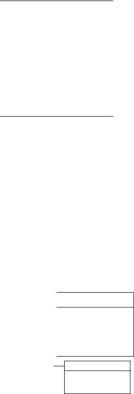
RIGGING AND HANDLING
Exercise care when moving the unit. Do not remove any packaging until the unit is near the place of installation. Rig the unit by attaching chain or cable slings to the round lifting holes provided in the base rails. Spreaders, whose length exceeds the largest dimension across the unit, MUST be used across the top of the unit.
Units may also be moved or lifted with a forklift, from the front or rear only, providing that an accessory skid is used.
LENGTH OF FORKS MUST BE A MINIMUM OF 90".
CAUTION: On gas heating units, an adhesive backed label is provided over the outside of the combustion air inlet opening to prevent moisture from entering the unit w hich could cause damage to electr ical components. Allow this closure label to remain in place until the combustion air hood is to be installed.
FIG. 1 - TYPICAL RIGGING
5
4
136-1/4"
FIG. 2 - CENTER OF GRAVITY
CLEARANCES
All units require certain clearances for proper operation and service. Installer must make provisions for adequate combustion and ventilation air in accordance with Section 5.3, Air for Combustion and Ventilation of the National Fuel Gas Code, ANSI Z223.1 (in U.S.A.) or Sections 7.2, 7.3 or 7.4 of Gas Installation Codes CAN/CGA-B149.1 and .2 (in Canada) and/or applicable provisions of the local building codes. Refer to Dimensions and Clearances table for the clearances required for combustible construction, servicing, and proper unit operation.
WARNING: Do not permit overhanging structures or shrubs to obstruct outdoor air discharge outlet, combustion air inlet or vent outlets.
Unitary Products Group |
3 |
530.18-N11Y
DUCTWORK
Ductwork should be designed and sized according to the methods in Manual Q of the Air Conditioning Contractors of America (ACCA).
A closed return duct system shall be used. This shall not preclude use of economizers or outdoor fresh air intake. The supply and return air duct connections at the unit should be made with flexible joints to minimize noise.
The supply and return air duct systems should be designed for the CFM and static requirements of the job. They should NOT be sized to match the dimensions of the duct connections on the unit.
CAUTION: When fastening ductwork to side duct flanges on unit, insert screws through duct flanges only. DO NOT insert screws through casing.
Outdoor ductwork must be insulated and waterproofed.
Refer to the Dimensions and Clearances figure for information concerning side and bottom supply and return air duct openings.
It is recommended that, in Canada, the outlet duct on gas heating units be provided with a removable access panel. It is recommended that this opening be accessible when the unit is installed in service, and of a size such that smoke or reflected light may be observed inside the casing to indicate the presence of leaks in the heat exchanger. The cover should be attached in a manner adequate to prevent leakage.
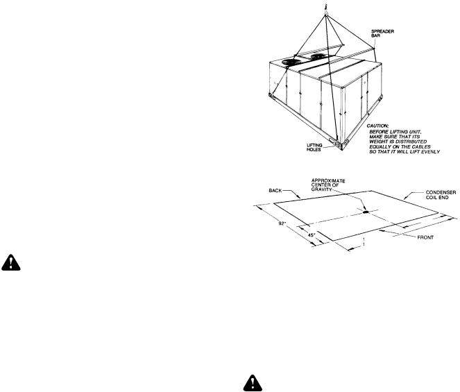
FIXED OUTDOOR AIR INTAKE DAMPER
This damper is shipped inside the return air compartment on units that are not provided with an economizer or a motorized damper option. It is completely assembled and ready for installation. A damper baffle inside of the hood is adjustable to provide variable amounts of outdoor air intake.
Gasketing and mounting screws are provided in a parts bag attached to the hood assembly. Apply gasketing to the three flange surfaces on the hood prior to installing the hood. Extend gasketing 1/4" beyond the top and bottom of the two side flanges to insure adequate sealing.
Adjusting the damper to the desired air flow may be done before mounting the hood into position or (after installation) by removing the front hood panel or the screen on the bottom of the hood. Damper baffle in position 1 will allow approximately 10% recirculated air flow, position 2 approximately 15% and, to allow approximately 25%, remove the damper baffle.
On units with bottom return air applications, install the damper assembly over the opening in the side return air access panel. Remove and discard the opening cover and the covering over the hood mounting holes (used for shipping) before installing. Secure with the screws provided.
On units with side return air applications, install the damper assembly on the return air ductwork as close to the unit as possible. Cut an opening 16" high by 18" wide in the ductwork to accommodate the damper. Using the holes in the hood flanges as a template, drill 9/64" dia. (#26 drill) holes into the ductwork and secure with the screws provided.
CAUTION: If outdoor air intake will not be required on units with bottom return air applications, the damper assembly should still be mounted on the side return air access panel, per the instructions above, to insure moisture is not drawn into the unit during operation. The covering over the mounting holes only need be removed. Do not remove the opening cover.
FIG. 3 - FIXED OUTDOOR AIR DAMPER
CONDENSATE DRAIN
Plumbing must conform to local codes. Use a sealing compound on male pipe threads. Install a condensate drain line from the 1" NPT female connection on the unit to an open drain.
FIG. 4 - RECOMMENDED DRAIN PIPING
NOTE: The condensate drain line MUST be trapped to provide proper drainage.
COMPRESSORS
Units are shipped with compressor mountings factory-adjusted and ready for operation.
CAUTION: Do Not loosen compressor mounting bolts.
FILTERS
2" filters are supplied with each unit.Filters must always be installed ahead of the evaporator coil and must be kept clean or replaced with same size and type. Dirty filters will reduce the capacity of the unit and will result in frosted coils or safety shutdown.Minimum filter area and required sizes are shown in the Physical Data Table.
SERVICE ACCESS
Access to all serviceable components is provided by the following removable panels:
•Compressor compartment
•Electric Heat compartment - DCE models
•Gas Heat compartment (Two panels) - DCG models
•Side Supply & Return Air compartments (Two panels)
•Blower compartment (Three panels)
•Main control box
•Filter compartment
•Outdoor Air compartment (Two panels)
Refer to the Dimensions and Clearances figure for location of these access panels.
CAUTION: Make sure that all screws and panel latches are replaced and properly positioned on the unit to maintain an air-tight seal.
4 |
Unitary Products Group |

530.18-N11Y
CONTROL WIRE SIZES
Wire Size1 AWG. Gauge
22 |
20 |
19 |
18 |
16 |
|
|
|
|
|
25 |
40 |
50 |
65 |
100 |
|
|
|
|
|
Maximum Wire Length2 Feet
Notes:
1. Solid, Class II copper wire
FIG. 5 - TYPICAL FIELD WIRING
Unitary Products Group |
5 |
530.18-N11Y
THERMOSTAT
The room thermostat should be located on an inside wall approximately 56" above the floor where it will not be subject to drafts, sun exposure or heat from electrical fixtures or appliances. Follow manufacturer’s instructions enclosed with thermostat for general installation procedure. Seven color coded insulated wires should be used to connect thermostat to unit.
POWER AND CONTROL WIRING
Field wiring to the unit must conform to provisions of the National Electrical Code, ANSI / NFPA No. 70 (in U.S.A.), current Canadian Electrical Code C22.1 (in Canada) and/or local ordinances. The unit must be electrically grounded in accordance with NEC and CEC (as specified above) and/or local codes. Voltage tolerances which must be maintained at the compressor terminals during starting and running conditions are indicated on the unit Rating Plate.
The internal wiring harness furnished with this unit is an integral part of a ETL and CGA design certified unit. Field alteration to comply with electrical codes should not be required.
A fused disconnect switch should be field provided for the unit. The switch must be separate from all other circuits. Wire entry at knockout openings require conduit fittings to comply with NEC (in U.S.A.), CEC (in Canada) and/or local codes. If any of the wire supplied with the unit must be replaced, replacement wire must be of the type shown on the wiring diagram and the same minimum gauge as the replaced wire.
Electrical line must be sized properly to carry the load. Each unit must be wired with a separate branch circuit fed directly from the meter panel and properly fused.
CAUTION: When connecting electrical power and control wiring to the unit, waterproof type connectors MUST BE USED so that water or moisture cannot be drawn into the unit during normal operation. The above waterproofing conditions will also apply when installing a field-supplied disconnect switch.
Refer to Typical Field Wiring Figure for typical field wiring and to the appropriate unit wiring diagram for control circuit and power wiring information.
OPTIONAL ELECTRIC HEATERS (DCE Models)
The factory installed heaters are wired for single point power supply. Power supply need only be brought into the single point terminal block and thermostat wiring to the low voltage terminal block located in the upper portion of the unit control box.
These ETL and CGA approved heaters are located within the central compartment of the unit with the heater elements extending into the supply air chamber. Refer to the Dimension and Clearances figure for access panel location.
Fuses are supplied, where required, by the factory. Some KW sizes require fuses and others do not. Refer to the Unit Application Data Table 1 for minmum CFM limitations and to Electrical Data Table.
TABLE 2 - GAS HEAT APPLICATION DATA
Input Capacity (Mbh) |
Output Capacity (Mbh) |
|
|
Temp. |
|||||
|
|
|
|
|
|
|
|
||
0 To |
2,000 To |
0 To |
2,000 To |
Gas |
|
Rise ° F |
|||
2,000 Feet |
4,500 Feet |
2,000 Feet |
4,500 Feet |
2 |
|
At |
|||
Above |
Above |
Above |
Above |
Rate |
|
Full Input 3 |
|||
3 |
|
||||||||
Sea Level |
Sea Level1 |
Sea Level |
Sea Level1 |
(Ft. /Hr.) |
|
|
|
||
Max. |
Min. |
Max. |
Min. |
Max. |
Max. |
|
Min. |
|
Max. |
300 |
150 |
270 |
135 |
240 |
213 |
279 |
20 |
|
50 |
|
|
|
|
|
|
|
|
|
|
400 |
200 |
360 |
180 |
320 |
281 |
372 |
30 |
|
60 |
|
|
|
|
|
|
|
|
|
|
NOTE: Heaters are shipped available for natural gas, but can be converted to L.P. / Propane with Kit Model No. 1NP0418.
1MBH rating should be reduced at the rate of 4 percent for each 1,000 feet above 4,500 feet. 2Based on maximum input and 1075 Btu/Ft3.
3The air flow must be adjusted to obtain a temperature rise within the range shown.
COMBUSTION DISCHARGE (DCG Models)
The products of combustion are discharged horizontally through two screened (hooded) openings on the upper gas heat access panel.
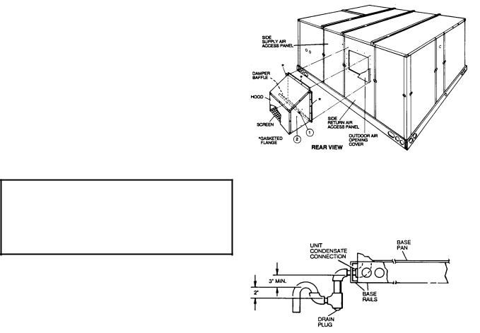
FIG. 6 - EXTERNAL SUPPLY CONNECTION EXTERNAL SHUT-OFF
GAS PIPING (DCG Models)
Proper sizing of gas piping depends on the cubic feet per hour of gas flow required, specific gravity of the gas and the length of run. “National Fuel Gas Code” Z223.1 (in U.S.A.) or the current Gas Installation Codes CAN/CGA-B149.1 and .2 (in Canada) should be followed in all cases unless superseded by local codes or gas utility requirements. See Pipe Sizing table.
The heating value of the gas may differ with locality. The value should be checked with the local gas utility.
NOTE: There may be a local gas utility requirement specifying a minimum diameter for gas piping. All units require a 1 inch pipe connection at the entrance fitting.
TABLE 3 - PIPE SIZING
Length in Feet |
Nominal Iron Pipe Size |
||
1 in. |
1-1/4 in. |
||
|
|||
10 |
520 |
1,050 |
|
20 |
350 |
730 |
|
30 |
285 |
590 |
|
40 |
245 |
500 |
|
50 |
215 |
440 |
|
60 |
195 |
400 |
|
70 |
180 |
370 |
|
80 |
170 |
350 |
|
90 |
160 |
320 |
|
100 |
150 |
305 |
|
Maximum capacity of pipe in cubic feet of gas per hour. (Based upon a pressure drop of 0.3 inch water column and 0.6 specific gravity gas).
GAS CONNECTION (DCG Models)
The gas supply line can be routed through the knockouts located on the front of the unit or through the opening provided in the unit’s base. Typical supply piping arrangements are shown in the Supply Connection figures. All pipe, fittings, etc. are field-supplied.
Two grommets are shipped in the blower compartment (in parts bag taped to the blower housing) of every unit with gas heat and should be used in the knockouts when the gas piping enters through the front of the unit.
After the gas supply piping has been installed, the bottom opening in the unit should be sealed to prevent water from leaking into the building.
Gas piping recommendations:
1.A drip leg and a ground joint union must be installed in the gas piping.
2.When required by local codes, a manual shut-off valve may have to be installed outside of the unit.
3.Use wrought iron or steel pipe for all gas lines. Pipe compound should be applied sparingly to male threads only.
6 |
Unitary Products Group |
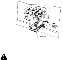
FIG. 7 - BOTTOM SUPPLY CONNECTION
EXTERNAL SHUT-OFF
WARNING: Natural gas may contain some propane. Propane,
being an excellent solvent, will quickly dissolve white lead or most standard commercial compounds. Therefore, a special pipe compound must be applied when wrought iron or steel pipe is used. Shellac base compounds such as Gaskolac or Stalastic, and compounds such as Rectorseal #5, Cyde’s or John Crane may be used.
4.All piping should be cleaned of dirt and scale by hammering on the outside of the pipe and blowing out the loose dirt and scale. Before initial start-up, be sure that all of the gas lines external to the unit have been purged of air.
5.The gas supply should be a separate line and installed in accordance with all safety codes as prescribed under “Limitations”. After the gas connections have been completed, open the main shut-off valve admitting normal gas pressure to the mains. Check all joints for leaks with soap solution or other material suitable for the purpose. NEVER USE A FLAME.
6.The furnace and its individual manual shut-off valve must be disconnected from the gas supply piping system during any pressure testing of that system at test pressures in excess of 1/2 psig (3.48kPa).
The furnace must be isolated from the gas supply piping system by closing its individual manual shut-off valve during any pressure testing of the gas supply piping system at test pressures equal to or less than 1/2 psig (3.48kPa).
7.A 1/8 inch NPT plugged tapping, accessible for test gage connection, must be installed immediately upstream of the gas supply connection to the furnace.
530.18-N11Y
L.P. UNITS, TANKS AND PIPING (DCG Models)
All gas heat units are shipped from the factory equipped for natural gas use only. The unit may be converted in the field for use with L.P./propane gas with accessory kit model number 1NP0418.
All L.P./propane gas equipment must conform to the safety standards of the National Fire Protection Association.
For satisfactory operation, L.P./propane gas pressure must be 8.8 inch W.C at the unit under full load. Maintaining proper gas pressure depends on three main factors:
1.The vaporization rate which depends on (a) the temperature of the liquid and (b) the “wetted surface” area of the container or containers.
2.The proper pressure regulation. (Two-stage regulation is recommended from the standpoint of both cost and efficiency.)
3.The pressure drop in the lines between regulators and between the second stage regulator and the appliance. Pipe size required will depend on the length of the pipe run and the total load of all appliances.
Complete information regarding tank sizing for vaporization, recommended regulator settings, and pipe sizing is available from most regulator manufacturers and L.P./propane gas suppliers.
L.P./propane gas is an excellent solvent and special pipe compound must be used when assembling piping for this gas as it will quickly dissolve white lead or most standard commercial compounds. Shellac base compounds such as Rectorseal #5 are satisfactory for this type of gas.
Check all connections for leaks when piping is completed, using a soap solution. NEVER USE A FLAME.
Unitary Products Group |
7 |
530.18-N11Y
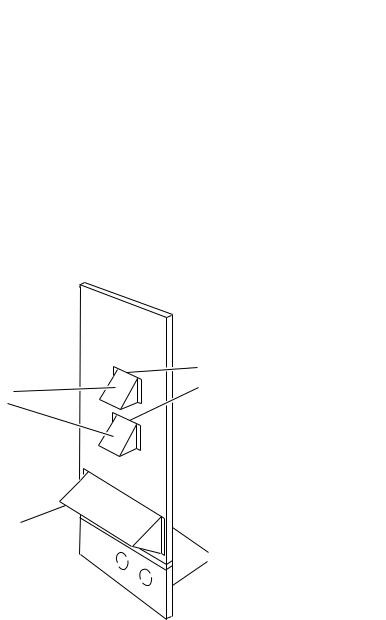
VENT AND COMBUSTION AIR HOODS (DCG Models)
Two vent hoods and a combustion air hood (with screens) are shipped attached to the blower housing in the blower compartment. These hoods must be installed to assure proper unit function. All hoods must be fastened to the outside of the gas heat access panel with the screws provided in the bag also attached to the blower housing.
The screen for the combustion air intake hood is secured to the inside of the access panel opening with four fasteners and the screws used for mounting the hood to the panel. The top flange of this hood slips in under the top of the access panel opening when installing. Refer to the Vent and Combustion Hood figure.
Each vent hood is installed by inserting the top flange of the hood into the slotted opening in the access panel and securing in place.
SLOTTED
OPENINGS IN VENT AIR ACCESS PANEL OUTLET
HOODS
COMBUSTION AIR INTAKE
HOOD
GAS HEAT
ACCESS
PANELS
FIG. 8 - VENT AND COMBUSTION AIR HOODS
OPTIONAL ECONOMIZER/MOTORIZED DAMPER RAIN HOOD
The instruction for the optional economizer/motorized damper rain hood can be found in form 44-320-2. Use these instructions when field assembling an economizer rain hood onto a unit. The outdoor and return air dampers, the damper actuator, the damper linkage, the outdoor and return air divider baffles, and all the control sensors are factory mounted as part of the "Factory installed" economizer option.
ENTHALPY SET POINT ADJUSTMENT
Remove the economizer access panel from the unit to check the following adjustments. Loosen but do not remove the two panel latches.
CAUTION: Extreme care must be exercised in turning both the setpoint and minimum position adjusting screws to prevent twisting them off.
1.The enthalpy set point may now be set by selecting the desired setpoint shown in the Enthalpy figure. Adjust as follows:
•For a single enthalpy operation, carefully turn the set point adjusting screw to the “A”, “B”, “C” or “D” setting corresponding to the lettered curve.
•For a dual enthalpy operation, carefully turn the set point adjusting screw fully clockwise past the “D” setting.
2.To check that the damper blades move smoothly without binding, carefully turn the minimum position adjusting screw fully clockwise and then energize and de-energize terminals “R” to “G”. With terminals “R” to “G” energized, turn the minimum position screw counterclockwise until the desired minimum position has been attained.
3.Replace the economizer access panel. Reposition the two latches horizontally and retighten the screws.
POWER EXHAUST/BAROMETRIC RELIEF DAMPER AND RAIN HOOD OPTION
The instructions for the power exhaust/barometric relief damper and rain hood can be found in form 44-320-10. The exhaust fan, all supporting brackets, angles, and the wiring are factory installed as part of the power exhaust option.
All of the components, including the dampers, hardware, and mounting instructions are shipped in a single package external from the unit. The hood must be field assembled and installed.
Power exhaust is not available as a field installed option.
8 |
Unitary Products Group |
 Loading...