


TECHNICAL GUIDE
SPLIT-SYSTEM AIR-COOLED
EVAPORATOR BLOWER
25, 30, 40 & 50 TON
LA300, LB360, 480 & 600


 1
1
This product was manufactured in a plant whose quality system is certified/registered as being
in conformity with ISO9001.
036-21335-002-A-1102
J
PROVEN PERFORMANCE
GENERAL
The LA/LB line is a flexible performer. LA300, LB360 & 480 can be positioned in up to 12 different positions and suspended in various positions. The LB600 can be positioned in up to 7 different arrangements and suspended also. The LA/ LB line will give you the power to condition large amounts of building space and the ability to conform to almost any situation.
FEATURING
•EASE OF SERVICE
•PUMP-OUT ON START-UP
•BASE SECTIONS (25, 30 & 40 Ton only)
•SUSPENSION PACKAGES
•HOT WATER COILS
•STEAM COILS (LA300 & LB360 only)
•WIDE RANGE OF BLOWER MOTORS
•A VARIETY OF DRIVE PACKAGES
•CONTROL BOX WITH LOW VOLTAGE TRANSFORMER AND MOTOR STARTER (motor, motor drive kit and motor overloads sold separately).
FOR DISTRIBUTION USE ONLY - NOT TO BE USED AT POINT OF RETAIL SALE
TABLE OF CONTENTS
DESCRIPTION . . . . . . . . . . . . . . . . . . . . . . . . . . . . . 4 MODULAR DESIGN . . . . . . . . . . . . . . . . . . . . . . . . . 4 FACTORY-MOUNTED COMPONENTS . . . . . . . . . . 4 ACCESSORIES . . . . . . . . . . . . . . . . . . . . . . . . . . . . . 4 GUIDE SPECIFICATIONS . . . . . . . . . . . . . . . . . . . 23
LIST OF FIGURES
Fig. |
Pg. |
1 PRODUCT NOMENCLATURE . . . . . . . . . . . . . . . . . 3 2 UNIT INSTALLATION . . . . . . . . . . . . . . . . . . . . . . . . 4 3 DETAILS FOR SECURING BOTTOM MOUNTING
SUPPORTS . . . . . . . . . . . . . . . . . . . . . . . . . . . . . . . . 6 4 LA300/LB360 WEIGHT DISTRIBUTION . . . . . . . . . 6 5 UNIT DIMENSIONS - LA300, LB360 & LB480 . . . . 11 6 25 TON LIQUID LINE SOLENOID
WIRING . . . . . . . . . . . . . . . . . . . . . . . . . . . . . . . . . . 11 7 30, 40 & 50 TON LIQUID LINE
SOLENOID WIRING . . . . . . . . . . . . . . . . . . . . . . . . 11 8 LA300 PIPING CONNECTIONS . . . . . . . . . . . . . . . 12 9 LB360 PIPING CONNECTIONS . . . . . . . . . . . . . . . 12 10 LB480 PIPING CONNECTIONS . . . . . . . . . . . . . . . 12 11 UNIT DIMENSIONS - LB600 . . . . . . . . . . . . . . . . . . 13 12 LB600 PIPING CONNECTIONS - END PANEL
DETAIL . . . . . . . . . . . . . . . . . . . . . . . . . . . . . . . . . . . 13 13 HOT WATER COIL DIMENSIONS . . . . . . . . . . . . . 14 14 STEAM COIL DIMENSIONS . . . . . . . . . . . . . . . . . . 14 15 BASE SECTION DIMENSIONS . . . . . . . . . . . . . . . 14 16 BLOWER CURVE LA300 & LB360 . . . . . . . . . . . . . 19 17 BLOWER CURVE LB480 . . . . . . . . . . . . . . . . . . . . 21 18 BLOWER CURVE LB600 . . . . . . . . . . . . . . . . . . . . 22
036-21335-002-A-1102
LIST OF TABLES
Tbl. |
Pg. |
1 STATIC RESISTANCES FOR UNIT ACCESSORIES . 5 2 UNIT MOUNTING DIMENSIONS . . . . . . . . . . . . . . . . . 5 3 CORNER WEIGHTS . . . . . . . . . . . . . . . . . . . . . . . . . . . 7 4 ACCESSORY OPERATING WEIGHT DISTRIBUTION
(LBS) . . . . . . . . . . . . . . . . . . . . . . . . . . . . . . . . . . . . . 7 5 UNIT BLOWER MOTOR DATA . . . . . . . . . . . . . . . . . . 7 6 UNIT DRIVE DATA . . . . . . . . . . . . . . . . . . . . . . . . . . . 8 7 MOTOR OVERLOAD ELEMENTS . . . . . . . . . . . . . . . . 8 8 HOT WATER COIL CAPACITIES. . . . . . . . . . . . . . . . . 9 9 CAPACITY CORRECTION & PRESSURE DROP
VS GPM . . . . . . . . . . . . . . . . . . . . . . . . . . . . . . . . . . . 9 10 STEAM COIL CAPACITIES (LA300 & LB360 ONLY) 10 11 CORRECTION FACTORS FOR HIGH STEAM . . . . . 10 12 UNIT DIMENSIONS - LA300, LB360 & LB480 . . . . . 11 13 HOT WATER COIL DIMENSIONS . . . . . . . . . . . . . . . 14 14 STEAM COIL DIMENSIONS . . . . . . . . . . . . . . . . . . . 14 15 BASE SECTIONS DIMENSIONS . . . . . . . . . . . . . . . . 15 16 PHYSICAL DATA . . . . . . . . . . . . . . . . . . . . . . . . . . . . 16 17 ELECTRICAL DATA . . . . . . . . . . . . . . . . . . . . . . . . . . 17 18 FAN PERFORMANCE DATA (25 TON) . . . . . . . . . . . 18 19 FAN PERFORMANCE DATA (30 TON) . . . . . . . . . . . 18 20 FAN PERFORMANCE DATA (40 TON) . . . . . . . . . . . 20 21 FAN PERFORMANCE DATA (50 TON) . . . . . . . . . . . 20
2 |
Unitary Products Group |
036-21335-002-A-1102
YORK SPLIT INDOOR PRODUCT NOMENCLATURE
L A 300 C 00 A 6 A AA 1 A
Model # |
Model Number |
Options |
|
|
|
Description |
|
|
|
|
|
|
|
|
L |
Product Category |
L = Air Handling Unit - Cooling |
F = Air Handling Unit - Heat Pump |
|
|
|
|
||
A |
Product Identifier |
A = R-22 Standard Efficiency 2-Pipe |
||
B = R-22 Standard Efficiency 4-Pipe |
||||
|
|
|||
|
|
|
|
|
|
Nominal Cooling |
300 = 25 Ton |
|
|
|
360 = 30 Ton |
|
||
300 |
Capacity |
|
||
480 = 40 Ton |
|
|||
|
MBH |
|
||
|
600 = 50 Ton |
|
||
|
|
|
||
|
|
|
|
|
C |
Heat Type |
C = Cooling Only |
|
|
|
|
|
|
|
00 |
Nominal Heating |
00 = No Heat Installed |
|
|
Capacity |
|
|
||
|
|
|
||
|
|
|
|
|
A |
Airflow Options |
A = None |
|
|
|
|
|
|
|
6 |
Voltage |
0 = None |
6 = 208/230-460-3-60 |
|
5 = 575-3-60 |
|
|||
|
|
|
||
|
|
|
|
|
A |
Factory Options |
A = None |
|
|
|
|
|
|
|
AA |
Special Options |
AA = None |
|
|
|
|
|
|
|
1 |
Product Generation |
1 = First Generation |
2 = Second Generation |
|
|
|
|
|
|
FIGURE 1: PRODUCT NOMENCLATURE
NOTE: LB600 matches with both HB480 and HB600 Outdoor Condensing Units for maximum efficiency.
NOTE: LB480 Indoor and HB480 Outdoor Units do match up, but do not meet ASHRAE 90.1 standards for efficiency.
Unitary Products Group |
3 |
DESCRIPTION
Evaporator blower units are designed with two distinct modules to provide maximum application flexibility. The 25, 30 and 40 ton units are shipped as single packages with the blower module mounted on top of the coil module, The blower module can be repositioned in the field to meet almost any installation requirement. Blower and coil modules for the 50 ton units are shipped separately to simplify handling. These modules can be connected in the field with the same flexibility as the smaller units.
The blower module includes the blower wheels and room for a field-mounted motor and drive. The coil module includes direct expansion coils, 2 in. throwaway filters, liquid line solenoid valves for both capacity reduction and pumpdown, thermal expansion valves, distributors and a condensate drain pan.
Every evaporator coil is pressurized with air to 325 psig and leak tested under water. After the headers are brazed onto the coil and the coil is installed in the unit, the coil is pressurized with a combination of Refrigerant-22 and nitrogen to 150 psig for pressure testing and additional leak testing. After the coil is evacuated and dehydrated, it is pressurized with a holding charge of Refrigerant-22 for storage and/or shipping.
Steam coils, hot water coils, base sections, suspension hardware, blower motors and drive packages are available as field-installed accessories to provide additional application flexibility.
These evaporator blowers, combined with condensing units, provide years of quiet, efficient and dependable operation. These units are manufactured under ISO 9001 Quality System Certification.
For Indoor Unit Installation details, please see document 035- 18496-000.
MODULAR DESIGN
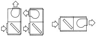
These evaporator blowers can be arranged for a variety of air discharge patterns in either the horizontal or vertical position.
FIGURE 2: UNIT INSTALLATION
036-21335-002-A-1102
Figure 2 shows three of the common installation arrangements. Refer to the unit installation instructions for other possibilities.
Units may be bottom-supported or ceiling-suspended and can be arranged to meet almost any space or duct requirements. Each unit is available with a choice of blower motors, drive packages and other accessories to make them suitable for most applications.
FACTORY-MOUNTED COMPONENTS
PART LOAD OPERATION These evaporator blowers have multiple coils with pre-piped distributors, expansion valves and solenoid valves. Field modifications are not required for part load operations. Capacity reduction not only provides economical operation, but also maintains more even temperature and humidity levels in the conditioned space.
EASY SERVICE Serviceable expansion valves are provided on every unit. These superior valves are factory-installed to provide many years of trouble-free operation. If service is required, it is not necessary to unbraze any joints.
PUMP-OUT Evaporator blowers include a solenoid valve for non-recycling pump-out. When a cooling requirement in the conditioned space is needed, the refrigerant is pumped into the high side of the system before unit start-up.
ACCESSORIES
BASE SECTIONS (25, 30 and 40 ton only: Base sections can be used to elevate units above the floor. If desired, outdoor air may be introduced through these sections by cutting an access opening to accommodate the outdoor air duct connection. These bases have a durable finish to match the evaporator blower unit. They may have to be insulated for certain applications.
SUSPENSION PACKAGES: These accessories can be used to suspend horizontal units from above without interfering with access to the unit. They can also be used for elevating a floor-mounted unit (either horizontal or vertical) to provide additional height for the installation of a trap at the condensate drain connection. All suspension packages can be used with vibration isolators.
HOT WATER COILS: Drainable water coils are available for field installation between the blower and the coil modules of both horizontal and vertical units. Since their casings match the dimensions and the finish of the basic units, they become an integral part of the unit after installation. The coils slide out of their casings for easy installation. Coils have copper tubes that have been mechanically expanded into aluminum fins. Both headers are located on the same end of the coil. Coils are leak-tested at 325 psig under water and dried before their connections are capped for storage and shipping.
4 |
Unitary Products Group |
036-21335-002-A-1102
STEAM COILS (LA300 & LB360 only): A steam coil is available on the 25 & 30 Ton for installation between the blower and coil modules of both horizontal and vertical units. Since the casing matches the dimensions and the finish of the basic unit, it becomes an integral part of the unit after installation. The coil slides out of the casings for easy installation and is pitched in the casings to facilitate condensate drainage. The coil has copper tubes that have been mechanically expanded into aluminum fins. Both headers are located on the same end of the coil. The coil is leak-tested at 325 psig and dried before the connections are capped for storage and shipping.
BLOWER MOTORS: Different HP motors are available for each unit to meet almost any air delivery requirement. All motors are UL approved, have permanently lubricated ball bearings and are field-mounted within the insulated cabinet of the units to minimize the transmission of sound to the sur-
rounding space. 5 HP motors are inherently protected. 7.5 HP - 15 HP require motor overload protection.
DRIVE PACKAGES: Different size pulleys and belts are available for each unit to provide a blower RPM range to meet almost any air delivery requirement. Variable pitch motor pulleys can be adjusted to provide the proper blower RPM. All drive packages are rated at least 25% above the nominal HP rating of the blower motor. Two-groove pulleys and two belts are provided on every drive package rated at 5 HP and above.
STARTERS AND HEATER ELEMENTS (7.5 - 15 HP): The blower motors that are available for the units do not have inherent protection and require external motor overload protection. See details in Table 7.
TABLE 1: STATIC RESISTANCES FOR UNIT ACCESSORIES
UNIT MODEL |
ACCESSORY |
|
|
CFM |
|
|
|
|
|
|
|
|
|
|
|
|
|
8,000 |
9,000 |
10,000 |
11,000 |
12,000 |
|
LA300 |
|
|
|
|
|
|
|
Hot Water Coil |
0.06 |
0.07 |
0.08 |
0.09 |
0.10 |
||
|
Steam Coil |
0.11 |
0.14 |
0.17 |
0.20 |
0.23 |
|
|
|
|
|
|
|
|
|
|
|
10,000 |
11,000 |
12,000 |
13,000 |
14,000 |
|
LB360 |
|
|
|
|
|
|
|
Hot Water Coil |
0.08 |
0.09 |
0.10 |
0.12 |
0.14 |
||
|
Steam Coil |
0.17 |
0.20 |
0.23 |
0.27 |
0.31 |
|
|
|
|
|
|
|
|
|
LB480 |
|
12,800 |
14,400 |
16,000 |
17,600 |
19,200 |
|
|
|
|
|
|
|
||
Hot Water Coil |
0.11 |
0.13 |
0.15 |
0.17 |
0.20 |
||
|
|||||||
|
|
|
|
|
|
|
|
LB600 |
|
16,000 |
18,000 |
20,000 |
22,000 |
24,000 |
|
|
|
|
|
|
|
||
Hot Water Coil |
0.15 |
0.18 |
0.21 |
0.24 |
0.28 |
||
|
|||||||
|
|
|
|
|
|
|
TABLE 2: UNIT MOUNTING DIMENSIONS1
LA/LB |
|
DIMENSIONS, INCHES |
|
UNIT |
AX |
BX |
CX |
|
|
|
|
300 |
69-1/4 |
49-1/16 |
26-5/8 |
|
|
|
|
|
|
|
|
360 |
69-1/4 |
49-1/16 |
26-5/8 |
|
|
|
|
|
|
|
|
480 |
84 |
50-9/16 |
34 |
|
|
|
1. See Figure 4 for dimensions AX, BX and CX.
Unitary Products Group |
5 |

036-21335-002-A-1102
NOTE: The following illustration shows how the channels
should be secured to the unit using the hardware
provided with the suspension accessory.
(2)9/16 HOLES FOR 1/2 HANGER RODS
|
|
SUSPENSION |
|
|
|
CHANNEL |
|
5/16 NUT, |
3 |
5/16 NUT, |
|
LOCKWASHER, |
|||
|
|||
FLATWASHER |
|
FLATWASHER |
|
3/8 NUT (USED |
|
|
|
AS SPACER) |
|
|
|
|
|
UNIT PANEL |
|
|
|
5/16 BOLT, |
|
|
|
FLAT-WASHER |
|
SIDE |
|
UNIT ANGLE |
|
PANEL |
|
|
FIGURE 3 : DETAILS FOR SECURING BOTTOM MOUNTING SUPPORTS
|
D |
|
|
|
AX |
BX |
VERTICAL LA300, LB360, LB480 |
||
|
||||
|
|
UNIT SUPPORTED FROM BELOW |
||
A |
|
BX |
|
|
|
|
|
|
|
3 |
|
|
|
|
|
|
C |
|
|
|
|
B LOWE R |
|
B LOWE R |
|
|
S E C T IO N |
|
|
1-1/2 |
|
|
S E C T IO N |
|
|
|
|
||
|
E V AP . C OIL |
B |
|
E V AP . |
HOR IZONT AL |
S E C T IO N |
|
|
C OIL |
|
|
|
S E C T IO N |
|
LE U360 O R 4 80 |
|
|
|
|
|
HE AT IN G C OIL |
2 |
B |
|
UNIT S US P E NDE D |
|
|||
|
|
|
|
|
F R OM A B OV E 3 |
|
|
|
|
|
|
|
A |
CX 4 C |
|
|
S US P E NS IO N |
|
|
|
|
ANG LE S |
1 |
BX |
|
|
|
|
|
|
|
|
D |
BX |
T he s ame c hannels c an be used in e ither position. W hen used to
1support at vertical unit, these c hannels s hould be c ut to match the bottom dimension of the e vaporator c oil s ection.
T he s uspension c hannels have two s ets of mounting holes to
2accommodate horizontal units with or without a heating c oil. O n a horizontal unit without a heating c oil, th e s uspension c hannels will e xtend 3" beyond both e nds of the unit.
3 |
T he s ame c hannels c an be used to s upport a horizontal, fl oor- |
|
mounted unit from below. |
||
|
||
4 |
After these bottom c hannels a re c ut per N ote 1, a new h ole will have |
|
to be drilled a t the c ut end if the unit is to be mounted on isolators . |
||
|
FIGURE 4 : LA300/LB360 WEIGHT DISTRIBUTION
6 |
Unitary Products Group |
036-21335-002-A-1102
TABLE 3: CORNER WEIGHTS
UNIT- |
|
Unit Weight |
|
|
|
|
|
|
MODEL |
Shipping |
|
Operation |
Configuration |
A |
B |
C |
D |
LA300 |
1180 |
|
1125 |
HORIZONTAL |
276 |
317 |
285 |
247 |
|
|
|
|
|
|
|||
|
VERTICAL |
262 |
301 |
301 |
262 |
|||
|
|
|
|
|||||
|
|
|
|
|
|
|
|
|
LB360 |
1180 |
|
1146 |
HORIZONTAL |
281 |
323 |
290 |
252 |
|
|
|
|
|
|
|||
|
VERTICAL |
266 |
307 |
307 |
266 |
|||
|
|
|
|
|||||
|
|
|
|
|
|
|
|
|
LB480 |
1510 |
|
1426 |
HORIZONTAL |
348 |
414 |
361 |
303 |
|
|
|
|
|
|
|||
|
VERTICAL |
292 |
348 |
427 |
359 |
|||
|
|
|
|
|||||
|
|
|
|
|
|
|
|
|
LB600 |
1572 |
|
1640 |
HORIZONTAL |
451 |
386 |
370 |
433 |
|
|
|
|
|
|
|||
|
VERTICAL |
484 |
414 |
342 |
400 |
|||
|
|
|
|
|||||
TABLE 4: ACCESSORY OPERATING WEIGHT DISTRIBUTION (LBS)1
ACCESSORY |
LA300 |
LB360 |
LB480 |
LB600 |
|
|
|
|
|
BASE2 |
25 |
25 |
30 |
45 |
HOT WATER COIL |
35 |
35 |
45 |
35 |
|
|
|
|
|
STEAM COIL 1 ROW |
30 |
30 |
35 |
50 |
1.These weights should be added to each point load in table 3.
2.This accessory can only be applied on units installed in the vertical position.
TABLE 5: UNIT BLOWER MOTOR DATA
UNIT MODEL |
HP |
MOTOR KIT |
FRAMESIZE |
VOLTAGE |
|
MODEL NUMBER |
(3PH-60HZ) |
||||
|
|
|
|||
|
|
|
|
|
|
|
|
2LR04605032 |
|
230/460 |
|
|
|
|
|
|
|
|
5 |
2LR04605023 |
184 |
208 |
|
LA300 |
|
|
|
|
|
|
2LR04605158 |
|
575 |
||
|
|
|
|
|
|
|
7.5 |
2LP04607133 |
213 |
230/460 |
|
|
|
|
|||
|
2LP04607158 |
575 |
|||
|
|
|
|||
|
|
|
|
|
|
|
|
2LR04605032 |
|
230/460 |
|
|
|
|
|
|
|
|
5 |
2LR04605023 |
184 |
208 |
|
|
|
|
|
|
|
|
|
2LR04605158 |
|
575 |
|
LB360 |
|
|
|
|
|
7.5 |
2LP04607133 |
213 |
208/230/460 |
||
|
|
|
|||
|
2LP04607158 |
575 |
|||
|
|
|
|||
|
|
|
|
|
|
|
10 |
2LP04610133 |
215 |
208/230/460 |
|
|
|
|
|||
|
2LP04610158 |
575 |
|||
|
|
|
|||
|
|
|
|
|
|
|
7.5 |
2LP04607133 |
213 |
208/230/460 |
|
|
|
|
|||
LB480 |
2LP04607158 |
575 |
|||
|
|
||||
|
|
|
|
||
10 |
2LP04610133 |
215 |
208/230/460 |
||
|
|||||
|
|
|
|||
|
2LP04610158 |
575 |
|||
|
|
|
|||
|
|
|
|
|
|
|
10 |
2LP04610133 |
215 |
208/230/460 |
|
|
|
|
|||
LB600 |
2LP04610158 |
575 |
|||
|
|
||||
|
|
|
|
||
15 |
2LP04615133 |
254 |
208/230/460 |
||
|
|||||
|
|
|
|||
|
2LP04615158 |
575 |
|||
|
|
|
|||
|
|
|
|
|
Unitary Products Group |
7 |
036-21335-002-A-1102
TABLE 6: UNIT DRIVE DATA
|
|
|
ADJUSTABLE MOTOR PULLEY |
FIXED BLOWER PULLEY |
|
BELTS |
||||
|
DRIVE KIT |
BLOWER |
|
|
|
|
|
|
|
|
UNIT |
|
|
|
|
|
|
PITCH |
|
||
MODEL |
RPM |
PITCH DIA. |
BORE |
PITCH DIA. |
BORE |
|
LENGTH |
|
||
MODEL |
NUMBER |
RANGE |
(IN.) |
(IN.) |
(IN.) |
|
(IN.) |
QTY. |
(IN.) |
DESIGNATION |
|
|
|
|
|
|
|
|
|
|
|
|
1LD0440 |
600 - 750 |
4.0 - 5.0 |
1 1/8 |
12.0 |
1 |
3/16 |
2 |
63.3 |
A62 |
LA300 |
|
|
|
|
|
|
|
|
|
|
1LD0407 |
700 - 850 |
4.2 - 5.2 |
1 3/8 |
11.0 |
1 |
3/16 |
2 |
63.3 |
A62 |
|
|
|
|
|
|
|
|
|
|
|
|
|
1LD0442 |
780 - 940 |
5.3 - 6.3 |
1 3/8 |
12.0 |
1 |
3/16 |
2 |
63.3 |
A62 |
|
|
|
|
|
|
|
|
|
|
|
|
1LD0415 |
636 - 795 |
4.0 - 5.0 |
1 1/8 |
11.0 |
1 |
3/16 |
2 |
63.3 |
A62 |
LB360 |
|
|
|
|
|
|
|
|
|
|
1LD0407 |
668 - 827 |
4.2 - 5.2 |
1 3/8 |
11.0 |
1 |
3/16 |
2 |
63.3 |
A62 |
|
|
|
|
|
|
|
|
|
|
|
|
|
1LD0408 |
827 - 986 |
5.3 - 6.3 |
1 3/8 |
11.0 |
1 |
3/16 |
2 |
59.7 |
A59 |
|
|
|
|
|
|
|
|
|
|
|
LB480 |
1LD0409 |
607 - 776 |
4.3 - 5.5 |
1 3/8 |
12.4 |
1 |
3/16 |
2 |
85.1 |
B84 |
|
|
|
|
|
|
|
|
|
|
|
|
1LD0410 |
776 - 917 |
5.4 - 6.6 |
1 3/8 |
12.4 |
1 |
3/16 |
2 |
86.8 |
B85 |
|
|
|
|
|
|
|
|
|
|
|
LB600 |
1LD0411 |
692 - 833 |
4.8 - 6.0 |
1 3/8 |
12.4 |
1 |
3/16 |
2 |
78.6 |
B78 |
|
|
|
|
|
|
|
|
|
|
|
|
1LD0412 |
762 - 931 |
5.4 - 6.6 |
1 5/8 |
12.4 |
1 |
3/16 |
2 |
76.8 |
B75 |
|
|
|
|
|
|
|
|
|
|
|
TABLE 7: MOTOR OVERLOAD ELEMENTS1
MOTOR HP |
VOLTAGE |
MODEL NUMBER |
|
|
|
|
|
|
208 |
2MP04704600 |
|
|
|
|
|
5 |
230 |
2MP04704600 |
|
|
|
||
460 |
2MP04704900 |
||
|
|||
|
|
|
|
|
575 |
2MP04705000 |
|
|
|
|
|
|
208 |
2MP04703700 |
|
|
|
|
|
7.5 |
230 |
2MP04704500 |
|
|
|
||
460 |
2MP04704300 |
||
|
|||
|
|
|
|
|
575 |
2MP04704000 |
|
|
|
|
|
|
208 |
2MP04701600 |
|
|
|
|
|
10 |
230 |
2MP04704100 |
|
|
|
||
460 |
2MP04704200 |
||
|
|||
|
|
|
|
|
575 |
2MP04704300 |
|
|
|
|
|
|
208 |
2MP04704400 |
|
|
|
|
|
15 |
230 |
2MP04701700 |
|
|
|
||
460 |
2MP04704500 |
||
|
|||
|
|
|
|
|
575 |
2MP04704600 |
|
|
|
|
1.These units are equipped from the factory with a correctly sized motor starter; overload elements are not factory supplied.
Do not operate the supply air blower motor above its nominal HP rating when a unit is equipped with a hot water coil accessory. Do not use steam in hot water coils.
Do not operate the supply air blower above its nominal HP rating when a unit is equipped with a steam coil accessory.
Although these coils are suitable for a much higher pressure, steam above 25 psig provides too much heat that could damage the blower motor.
Note: Three elements required per unit.
8 |
Unitary Products Group |
 Loading...