


INSTALLATION INSTRUCTION
TABLE OF CONTENTS
GENERAL INFORMATION . . . . . . . . . . . . . . . . . . . . 2 INSPECTION . . . . . . . . . . . . . . . . . . . . . . . . . . . . . . 2 REFERENCE . . . . . . . . . . . . . . . . . . . . . . . . . . . . . . 2 LIMITATIONS . . . . . . . . . . . . . . . . . . . . . . . . . . . . . . 2 CHECK ELECTRICAL POWER SUPPLY . . . . . . . . . 2 SELECTING EQUIPMENT LOCATION . . . . . . . . . . 2
INSTALLATION . . . . . . . . . . . . . . . . . . . . . . . . . . 4
OUTDOOR UNIT . . . . . . . . . . . . . . . . . . . . . . . . . . . . 4 INDOOR UNITS . . . . . . . . . . . . . . . . . . . . . . . . . . . . 4 REFRIGERANT LINE (SWEAT FIT) . . . . . . . . . . . . . 4 INSULATION OF VAPOR LINE . . . . . . . . . . . . . . . . 4 RE-ASSEMBLING, BRAZING AND CLEANING OF JOINT CONNECTIONS . . . . . . . . . . . . . . . . . . . . . . 5 REFRIGERANT LINE SUPPORT . . . . . . . . . . . . . . . 5 CHARGING AND LEAK TESTING . . . . . . . . . . . . . . 5 TOTAL LINE LENGTH . . . . . . . . . . . . . . . . . . . . . . . 5 ORIFICE SELECTION (ON SWEAT FIT COILS) . . . 5 REFRIGERANT VALVE OPERATION . . . . . . . . . . . 6 OIL TRAPPING . . . . . . . . . . . . . . . . . . . . . . . . . . . . . 6
SYSTEM CHARGE . . . . . . . . . . . . . . . . . . . . . . . 8
MEASUREMENT METHOD . . . . . . . . . . . . . . . . . . . 8 SUPERHEAT CHARGING METHOD . . . . . . . . . . . . 8 CHECKOUT PROCEDURE . . . . . . . . . . . . . . . . . . 10 SYSTEM OPERATION CHECKOUT . . . . . . . . . . . 10
CAUTION:READ ALL SAFETY GUIDES BEFORE YOU START TO INSTALL YOUR UNIT.
SAVE THIS MANUAL
OUTDOOR SPLIT-SYSTEM
AIR CONDITIONER
MODELS: 10, 12, 13 AND 14 SEER
1 PHASE - 1.5 TO 5 TONS
035-13606-003 Rev. A (202)
035-13606-003 Rev. A (202)
GENERAL INFORMATION
These outdoor units are designed to be connected to a matching UPG indoor coil with sweat connection lines. These units are factory charged with refrigerant for a matching indoor coil plus 15 feet of field supplied line. The outside unit is designed to be placed alongside or at the back of the home, remote from the indoor coil. The outdoor unit has been factory run-tested and all components of the system are ready for easy, immediate installation.
INSPECTION
Check the unit thoroughly for shipping damage, Unusually rough handling during shipment may loosen fan motors, compressors, or other components. Be sure that the unit is ready to operate before installing it. If there is damage, file a claim with the shipper. See Form 50.15-NM for more information.
REFERENCE
Use this instruction in conjunction with the instructions for the appropriate indoor unit, air moving system and accessories.
Installer should pay particular attention to the words NOTE, CAUTION and WARNING.
NOTES are intended to clarify or make the installation easier.
CAUTIONS identify procedures which, if not followed carefully, could result in personal injury, property damage or equipment damage.
WARNINGS are given to alert the installer that severe personal injury, death or equipment damage may result if installation procedures are not followed properly.
LIMITATIONS
The unit should be installed in accordance with all national and local codes and regulations which govern the installation of this type of equipment. In lieu of local codes, the equipment should be installed in accordance with National Electric Code, and in accordance with the recommendations made by the National Board of Fire Underwriters.
Limitations for the indoor unit, coil and appropriate accessories must also be observed.
The outdoor unit must not be installed with any duct work in the air stream. The outdoor fan is the propeller type and is not designed to operate against any additional external static pressure.
The maximum and minimum conditions for operation must be observed to assure a system that will give maximum performance with minimum service.
The manufacturer is not responsible for the performance of a mismatched system. The outdoor unit must be installed with a compatible indoor unit as designated in the specification data or in the Directory of Certified Unitary Heat Pumps published by the Air Conditioning and Refrigeration Institute. Using unmatched components may not only affect the performance of the system, but may also void the warranty of the equipment.
Do not install any coil in a furnace which is to be operated during the heating season without attaching the refrigerant lines to the coil. Allowing the coil charge to enter the refrigerant lines prevents excessive refrigerant pressure build-up and possible coil damage.
Table 1: APPLICATION LIMITATIONS
Ambient Air Temperature |
Air Temperature on |
||
on Outdoor Coil |
Indoor Coil |
||
Min. °DB |
Max. °DB |
Min. |
Max. |
50 |
120 |
57 |
72 |
CHECK ELECTRICAL POWER SUPPLY
The electrical power should be checked to determine if adequate power is available, and near constant voltage can be maintained. If there is any question concerning the power supply, contact the local power company for corrections; otherwise, unsatisfactory performance may result.
SELECTING EQUIPMENT LOCATION
Several important factors must be considered before selecting the site for the outdoor unit:
•Distance to indoor coil
•Proximity to the structure
•Proximity to vents and exhaust systems
•Ability to service
•Sound transmission
•Air circulation
•Wind direction
•Relationship between structure, sun, and unit
•Distance from power source
•Water drainage
•Local codes
Locate the outdoor unit near enough to the indoor coil vicinity to eliminate lengthy refrigerant line runs. Do not locate the outdoor unit so it discharges air under eaves or gutters. Rain or snow melt-off should not be able to run off a roof and down upon the unit. Be sure vents are not located upwind from the outdoor unit.
2 |
Unitary Products Group |
035-13606-003 Rev. A (202)
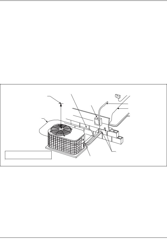
A minimum clearance of 18 inches is required for service at the control panel and compressor compartments access. A 10 inch clearance is required for the air inlet to the outdoor coil around the perimeter of the unit. The air discharge of the unit requires a 60 inch clearance between the top of the unit and any obstruction. See Figure 1.
The length of the refrigerant tubing, between the outdoor unit and indoor coil, should be as short as possible to avoid capacity and efficiency loss. Excessive spacing of the outdoor unit from the home can lead to the refrigerant lines being restricted by trampling or by being punctured by lawn mowers. Locate the outdoor unit away from bedroom windows or other rooms where sound might be objectionable.
Adverse effects of prevailing winds, blowing snow or sleet onto the outdoor coil can be eliminated by placing the outdoor unit where the wind does not blow across the unit. Trees, shrubs, corners of buildings and fences standing off from the coil can reduce capacity loss due to wind chill effect.
Provide ample clearance from shrubs to allow adequate air to pass across the outdoor coil without leaves or branches being pulled into the coil.
Consideration should be given to the distance and routing of electrical service that would have to be run to connect the outdoor unit.
The unit must be located outdoors and must not be connected to duct work. It is recommended the outdoor unit be mounted upon a solid base that will not shift or settle. Top of base should be two inches above grade. Thought should be given to water drainage away from the outdoor unit. Drain holes in the base pan must be kept clear.
|
MINIMUM 24” SERVICE ACCESS |
THERMOSTAT |
TO FURNACE OR |
|
60” OVERHEAD |
CLEARANCE ON ONE SIDE |
|||
|
||||
|
AIR HANDLER |
|||
CLEARANCE |
WEATHERPROOF |
|
||
|
TERMINAL BLOCK |
|||
|
DISCONNECT |
|
||
|
|
|
||
|
SWITCH |
|
NEC CLASS 1 WIRING |
|
|
|
|
NEC CLASS 2 WIRING |
|
10” CLEARANCE |
|
|
TO INDOOR COIL |
|
COIL AREA |
|
|
SEAL OPENING(S) WITH
NOTE: ALL OUTDOOR WIRING PERMAGUM OR EQUIVALENT
MUST BE WEATHERPROOF.
CONTROL ACCESS PANEL
FIGURE 1 : TYPICAL RESIDENTIAL OUTDOOR UNIT LOCATION
Unitary Products Group |
3 |
035-13606-003 Rev. A (202)
INSTALLATION
OUTDOOR UNIT
After the site has been selected, a solid base pad that will not shift or settle should be provided. The base pad should not come in contact with the foundation or side of the structure because sound may be transmitted to the residence. The pad should be located far enough away from the structure so the outdoor unit is not closer than its minimum distances. See Figure 1. Set the outdoor unit upon the pad with care to avoid damage..
Do not remove the protective caps or plugs from the unit refrigerant connections until the refrigerant lines are run and ready for final connection. If this procedure is not observed, dirt and other particles will get into the system and plug various orifices and small tubes.
INDOOR UNITS
Install the indoor coil in the furnace or air handler according to the installation instructions packed with each component.
REFRIGERANT LINE (SWEAT FIT)
The following steps are very important when setting up a refrigeration system and need to be followed completely to insure that a strong, flexible and leak tight system is obtained.
The installation of the copper refrigerant tubing must be done with care to obtain reliable, trouble-free operation.
1.Selection of proper refrigerant tubing grade and size.
2.Refrigerant line routing, cutting and fitting.
3.Insulating the vapor line.
4.Connecting the refrigerant lines to the indoor coil and outdoor unit.
5.Proper preparation of joint connections.
6.Reassembling, cleaning and brazing the joint connections.
7.Pressure leak test all joints.
8.Evacuate refrigerant lines and indoor coil.
9.Charging refrigeration system (If the line length is other than 15 feet). See Table 2.
Table 2: REFRIGERANT LINE CHARGE
LIQUID OD |
VAPOR OD |
R-22 CHARGE, OZ/FT |
3/8" |
5/8" |
0.66 |
3/8" |
3/4" |
0.68 |
3/8" |
7/8" |
0.70 |
3/8" |
1-1/8" |
0.76 |
Use only ACR grade copper tubing and keep ends sealed until joints are made.
The correct diameters of the refrigerant lines are listed in the Tabular Data Sheet.
For best performance, select routing of refrigerant lines for minimum distance and fewest number of bends.
Determine the path that the refrigerant lines will follow.
Starting at either the indoor coil or the outdoor unit refrigerant line connections, carefully measure, cut, de-burr and fit copper refrigerant lines along the path previously determined.
NOTE: If it is necessary for bends to be formed in the vapor line, the radius should not be less than 12 inches.
Cut ends of the copper tubing square.
Remove all burrs from tubing with a reamer, file or de-burring tool.
When the indoor coil is above the outdoor unit, the vapor line should be sloped toward the outdoor unit with a fall of at least 1/4 inch per 5 feet.
When the outdoor unit is above the indoor coil the horizontal runs should be sloped toward the outdoor unit as described above.
INSULATION OF VAPOR LINE
Insulate vapor line with 3/8" (or that required by local code) closed cell insulation.
Slide tubing insulation onto the vapor line so that it is covered completely from the indoor coil to the outdoor unit. Be sure that the tubing is capped before sliding on insulation.
It is not necessary to insulate the liquid line, unless it is subject to excess heat in an uninsulated area.
NOTE: In areas of extreme temperatures and humidity, additional insulation may be required to prevent excessive condensation and loss of capacity.
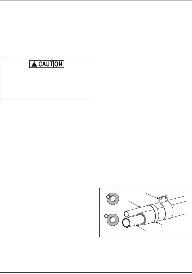
Do not insulate liquid line and vapor line together. Liquid line should not be in contact with the vapor line. See Figure 2.
Tape
Liquid
Line
Incorrect
Sheet Metal Hanger
Correct
Insulated Vapor Line
FIGURE 2 : INSULATION OF VAPOR LINE
4 |
Unitary Products Group |
 Loading...