


 Loading...


 YST-SW200
Active Servo Processing Subwoofer System
Built-in 100W Power Amplifier
2 Way Selectability for Connections
High Frequency Cut-off Point (HIGH CUT) Control
PHASE Switch
Remote Control Capability
Thank you for selecting this YAMAHA Subwoofer System.
OWNER’S MANUAL |
|
CONTENTS |
|
Safety Instructions.................... |
2 |
Supplied Accessories............... |
3 |
Features ................................... |
4 |
Placement ................................ |
4 |
Connections ............................. |
5 |
Controls and Their Functions ... |
8 |
Adjusting Volume Balance...... |
10 |
Notes about the Remote |
|
Control Transmitter ................. |
12 |
Troubleshooting ...................... |
12 |
Specifications ......................... |
13 |
Active Servo Technology ........ |
13 |
IMPORTANT!
Please record the serial number of this unit in the space below.
Model:
Serial No.:
The serial number is located on the rear of the unit.
Retain this Owner’s Manual in a safe
place for future reference.
WARNING
TO REDUCE THE RISK OF FIRE OR
ELECTRIC SHOCK, DO NOT EXPOSE
THIS UNIT TO RAIN OR MOISTURE.
CAUTION
RISK OF ELECTRIC SHOCK
DO NOT OPEN
CAUTION: TO REDUCE THE RISK OF
ELECTRIC SHOCK, DO NOT REMOVE
COVER (OR BACK), NO USER-SERVICEABLE PARTS INSIDE, REFER SERVICING TO QUALIFIED SERVICE PERSONNEL.
• Explanation of Graphical Symbols
The lightning flash with arrowhead
symbol, within an equilateral triangle,
is intended to alert you to the presence of uninsulated “dangerous voltage” within the product’s enclosure that may be of sufficient
magnitude to constitute a risk of
electric shock to persons.
The exclamation point within an equilateral triangle is intended to alert
you to the presence of important operating and maintenance (servicing) instructions in the
literature accompanying the
appliance.

SAFETY INSTRUCTIONS
1Read Instructions – All the safety and operating instructions should be read before the unit is operated.
2Retain Instructions – The safety and operating instructions should be retained for future reference.
3Heed Warnings – All warnings on the unit and in the operating instructions should be adhered to.
4Follow Instructions – All operating and other instructions should be followed.
5Water and Moisture – The unit should not be used near water – for example, near a bathtub, washbowl, kitchen sink, laundry tub, in a wet basement, or near a swimming pool, etc.
6Carts and Stands – The unit should be used only with a cart or stand that is recommended by the manufacturer.
6A A unit and cart combination should be moved with care. Quick stops, excessive force, and uneven surfaces may cause the unit and cart combination to overturn.
7Wall or Ceiling Mounting – The unit
should be mounted to a wall or ceiling only as recommended by the manufacturer.
8Ventilation – The unit should be situated so that its location or position does not interfere with its proper ventilation. For example, the unit should not be situated on a bed, sofa, rug, or similar surface, that may block the ventilation openings; or placed in a built-in installation, such as a bookcase or cabinet that may impede the flow of air through the ventilation openings.
9Heat – The unit should be situated away from heat sources such as radiators, stoves, or other appliances that produce heat.
10Power Sources – The unit should be connected to a power supply only of the type described in the operating instructions or as marked on the unit.
11Power-Cord Protection – Power-supply cords should be routed so that they are not likely to be walked on or pinched by items placed upon or against them, paying particular attention to cords at plugs, convenience receptacles, and the point where they exit from the unit.
12Cleaning – The unit should be cleaned only as recommended by the manufacturer.
13Nonuse Periods – The power cord of the unit should be unplugged from the outlet when left unused for a long period of time.
14Object and Liquid Entry – Care should be taken so that objects do not fall into and liquids are not spilled into the inside of the unit.
15Damage Requiring Service – The unit should be serviced by qualified service personnel when:
A.The power-supply cord or the plug has been damaged; or
B.Objects have fallen, or liquid has been spilled into the unit; or
C.The unit has been exposed to rain; or
D.The unit does not appear to operate normally or exhibits a marked change in performance; or
E.The unit has been dropped, or the cabinet damaged.
16Servicing – The user should not attempt to service the unit beyond those means described in the operating instructions. All other servicing should be referred to qualified service personnel.
17Power Lines – An outdoor antenna should be located away from power lines.
18Grounding or Polarization – Precautions should be taken so that the grounding or polarization is not defeated.
CAUTION: READ THIS BEFORE OPERATING YOUR UNIT
1To assure the finest performance, please read this manual carefully. Keep it in a safe place for future reference.
2Install this unit in a cool, dry, clean place – away from windows, heat sources, sources of excessive vibration, dust, moisture and cold. Avoid sources of humming (transformers, motors). To prevent fire or electrical shock, do not expose the unit to rain or water.
3Never open the cabinet. If something drops into the set, contact your dealer.
4Do not use force on switches, controls or connection wires. When moving the unit, first disconnect the power plug and the wires connected to other equipment. Never pull the wire itself.
5Do not attempt to clean the unit with chemical solvents; this might damage the finish. Use a clean, dry cloth.
6Be sure to read the “TROUBLESHOOTING” section regarding common operating errors before concluding that the unit is faulty.
7When not planning to use this unit for long periods of time (ie., vacation, etc.), disconnect the AC power plug from the wall outlet.
8To prevent lightning damage, disconnect the AC power plug when there is an electrical storm.
9Since this unit has a built-in power amplifier, heat will radiate from the rear panel. Therefore, place the unit at least 10 cm (4 inches) away from the wall. Also, do not position with the rear panel facing down on the floor or other surface.
10Super-bass frequencies reproduced by this unit may cause a turntable to generate a howling sound. In such a case, move this unit away from the turntable.
11This unit features a magnetically shielded design, but there is still a chance that placing it too close to a TV set might impair picture color. Should this happen, move this unit away from the TV set.
12If you hear distortion (i.e., unnatural, intermittent “rapping” or “hammering” sounds) coming from this unit, reduce the volume level. Extremely loud playing of a movie soundtrack’s low frequency, bass-heavy sounds or similarly loud popular music passages can damage this speaker system.
2
FCC INFORMATION
1. IMPORTANT NOTICE : DO NOT MODIFY THIS UNIT! |
Compliance with FCC regulations does not guarantee that |
|
This product, when installed as indicated in the |
interference will not occur in all installations. If this product |
|
instructions contained in this manual, meets FCC |
is found to be the source of interference, which can be |
|
requirements. Modifications not expressly approved by |
determined by turning the unit “OFF” and “ON”, please try |
|
Yamaha may void your authority, granted by the FCC, to |
to eliminate the problem by using one of the following |
|
use the product. |
measures: |
|
2. IMPORTANT : When connecting this product to |
Relocate either this product or the device that is being |
|
accessories and/or another product use only high quality |
affected by the interference. |
|
shielded cables. Cable/s supplied with this product |
Utilize power outlets that are on different branch (circuit |
|
MUST be used. Follow all installation instructions. |
||
breaker or fuse) circuits or install AC line filter/s. |
||
Failure to follow instructions could void your FCC |
||
|
||
authorization to use this product in the USA. |
In the case of radio or TV interference, relocate/reorient the |
|
3. NOTE : This product has been tested and found to |
antenna. If the antenna lead-in is 300 ohm ribbon lead, |
|
comply with the requirements listed in FCC Regulations, |
change the lead-in to coaxial type cable. |
|
Part 15 for Class “B” digital devices. Compliance with |
If these corrective measures do not produce satisfactory |
|
these requirements provides a reasonable level of |
||
results, please contact the local retailer authorized to |
||
assurance that your use of this product in a residential |
||
distribute this type of product. If you can not locate the |
||
environment will not result in harmful interference with |
||
appropriate retailer, please contact Yamaha Electronics |
||
other electronic devices. |
||
Corp., U.S.A. 6660 Orangethorpe Ave, Buena Park, CA |
||
This equipment generates/uses radio frequencies and, if |
||
90620. |
||
not installed and used according to the instructions |
The above statements apply ONLY to those products |
|
found in the users manual, may cause interference |
||
distributed by Yamaha Corporation of America or its |
||
harmful to the operation of other electronic devices. |
||
subsidiaries. |
||
|
We Want You Listening For A Lifetime
YAMAHA and the Electronic Industries Association’s Consumer Electronics Group want you to get the most out of your equipment by playing it at a safe level. One that lets the sound come through loud and clear without annoying blaring or distortion – and, most importantly, without affecting your sensitive hearing. Since hearing damage from loud sounds is
often undetectable until it is too late, YAMAHA and the Electronic Industries Association’s Consumer Electronics Group recommend you to avoid prolonged exposure from excessive volume levels.
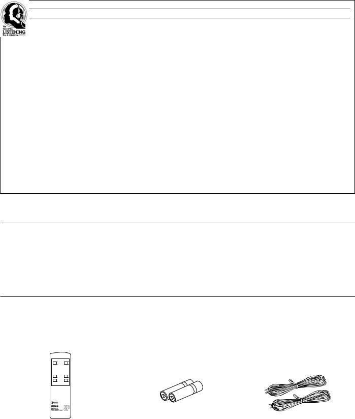
SUPPLIED ACCESSORIES
After unpacking, check that the following parts are contained.
Remote Control Transmitter |
Batteries (size AA, R6, UM-3) |
Speaker Cords |
POWER OUTPUT
ON/OFF
HIGH-CUT VOLUME
UP
DOWN
3
FEATURES
•This subwoofer system employs YAMAHA Active Servo Technology which YAMAHA developed for reproducing higher quality super-bass sound. (Refer to page 13 for details on Active Servo Technology.)
This unit does not only enhance bass frequency response of sound output in your audio system, but, by reproducing the bass frequencies, the subwoofer permits your existing amplifier and speakers to operate under less strenuous conditions, improving overall system performance.
•This unit can be added easily to your existing audio system by connecting to either the speaker terminals or the line output (pin jack) terminals of the amplifier.
•For the effective use of this unit, this unit’s super-bass sound must be matched to the sounds on your main speakers. Therefore, this unit employs the continuously variable high frequency cut-off point (HIGH-CUT) control. Moreover, the PHASE switch allows you to select better sound quality according to the listening condition.
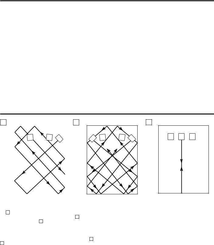
PLACEMENT
A |
|
B |
|
|
|
If using one subwoofer system, it is recommended to place it on the outside of either the right or the left main speaker. (See
fig. A .) If using two systems, it is recommended to place them on the outside of each main speaker. (See fig. B .) The
placement shown in fig. C is also possible, however, if the subwoofer system is placed directly facing the wall, the bass effect may die because the sound from it and the sound reflected by the wall will collide. To prevent this, face the subwoofer system obliquely to the wall as shown in fig. A or
B .
C
One subwoofer system will have a good effect on your audio system, however, the use of two subwoofer systems is recommended to obtain more presence.
Note
There may be a case that you cannot obtain enough superbass sounds from this unit when listening at the middle of the room. This is because the “standing waves” occur between two parallel walls and the bass sounds are canceled.
In such a case, face the unit obliquely to the wall. It also may be necessary to break up the parallel surfaces by placing bookshelves etc. along the walls.
4

CONNECTIONS
•Before attempting to make any connections to or from this unit, be sure to first switch OFF the power to this unit and to any other components to which connections are being made.
•When making connections between this unit and other components, be sure all connections are made correctly and consistently, that is to say L (left) to L, R (right) to R, “+” to “+” and “–” to “–”.
•This unit can be connected to either the speaker terminals or the line output (pin jack) terminals of the amplifier. Choose one of the ways shown below according to your audio system. Also, refer to the owner’s manual for each component to be connected to this unit.
CONNECTING TO SPEAKER TERMINALS OF THE AMPLIFIER
•Disconnect your main speakers from the amplifier and connect them to this unit.
•To connect this unit to the amplifier, use the provided speaker cords.
If using one YST-SW200
Right speaker |
Left speaker |
This unit
OUTPUT |
TO SPEAKERS |
FROM AMPLIFIER |
INPUT1 |
INPUT2 
 PHASE
PHASE
NOM REV
Amplifier
 To AC outlet
If using two YST-SW200s
Right speaker |
Left speaker |
This unit
OUTPUT |
TO SPEAKERS |
FROM AMPLIFIER |
INPUT1 |
INPUT2 
 PHASE
PHASE
NOM REV
OUTPUT |
TO SPEAKERS |
FROM AMPLIFIER |
INPUT1 |
INPUT2 
 PHASE
PHASE
NOM REV
This unit
Amplifier
To AC outlet |
To AC outlet |
5
Loading...