


FZS10V
Table of contents
 Loading...
OWNER’S MANUAL
FZS10V
FZS10VC
LIT-11626-19-79
3C3-28199-10
EAU10041

INTRODUCTION
EAU10080
Congratulations on your purchase of the Yamaha FZS10V/FZS10VC. This model is the result of Yamaha’s vast experience
in the production of fine sporting, touring, and pacesetting racing machines. It represents the high degree of craftsmanship
and reliability that have made Yamaha a leader in these fields.
This manual will give you an understanding of the operation, inspection, and basic maintenance of this motorcycle. If you
have any questions concerning the operation or maintenance of your motorcycle, please consult a Yamaha dealer.
The design and manufacture of this Yamaha motorcycle fully comply with the emissions standards for clean air applicable at
the date of manufacture. Yamaha has met these standards without reducing the performance or economy of operation of the
motorcycle. To maintain these high standards, it is important that you and your Yamaha dealer pay close attention to the
recommended maintenance schedules and operating instructions contained within this manual.
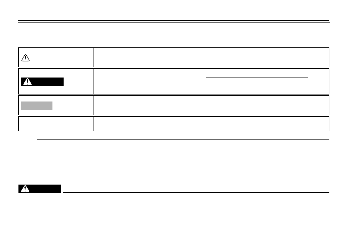
IMPORTANT MANUAL INFORMATION
Particularly important information is distinguished in this manual by the following notations:
The Safety Alert Symbol means ATTENTION! BECOME ALERT! YOUR SAFETY IS
INVOLVED!
EAU10131
WARNING
Failure to follow WARNING instructions could result in severe injury or death
motorcycle operator, a bystander or a person inspecting or repairing the motor-
to the
cycle.
CAUTION:
NOTE:
A CAUTION indicates special precautions that must be taken to avoid damage to
the motorcycle.
A NOTE provides key information to make procedures easier or clearer.
NOTE:
● This manual should be considered a permanent part of this motorcycle and should remain with it even if the motorcycle
is subsequently sold.
● Yamaha continually seeks advancements in product design and quality. Therefore, while this manual contains the most
current product information available at the time of printing, there may be minor discrepancies between your motorcycle
and this manual. If you have any questions concerning this manual, please consult your Yamaha dealer.
EWA10010
WARNING
PLEASE READ THIS MANUAL AND THE “YOU AND YOUR MOTORCYCLE: RIDING TIPS” BOOKLET CAREFULLY
AND COMPLETELY BEFORE OPERATING THIS MOTORCYCLE. DO NOT ATTEMPT TO OPERATE THIS MOTORCYCLE UNTIL YOU HAVE ATTAINED ADEQUATE KNOWLEDGE OF ITS CONTROLS AND OPERATING FEATURES
IMPORTANT MANUAL INFORMATION
AND UNTIL YOU HAVE BEEN TRAINED IN SAFE AND PROPER RIDING TECHNIQUES. REGULAR INSPECTIONS
AND CAREFUL MAINTENANCE, ALONG WITH GOOD RIDING SKILLS, WILL ENSURE THAT YOU SAFELY ENJOY
THE CAPABILITIES AND THE RELIABILITY OF THIS MOTORCYCLE.
*Product and specifications are subject to change without notice.
IMPORTANT MANUAL INFORMATION
AFFIX DEALER
LABEL HERE
FZS10V/FZS10VC
OWNER’S MANUAL
©2005 by Yamaha Motor Corporation, U.S.A.
1st edition, December 2005
All rights reserved.
Any reprinting or unauthorized use
without the written permission of
Yamaha Motor Corporation, U.S.A.
is expressly prohibited.
Printed in Japan.
P/N LIT-11626-19-79
EAU10192

TABLE OF CONTENTS
SAFETY INFORMATION ..................1-1
Location of important labels ...........1-5
DESCRIPTION ..................................2-1
Left view ..........................................2-1
Right view........................................2-2
Controls and instruments ................2-3
INSTRUMENT AND CONTROL
FUNCTIONS.......................................3-1
Main switch/steering lock ................3-1
Indicator and warning lights ............3-2
Multi-function meter unit .................3-4
Handlebar switches ........................3-8
Clutch lever ....................................3-9
Shift pedal ......................................3-9
Brake lever ...................................3-10
Brake pedal ..................................3-10
Fuel tank cap ................................3-10
Fuel ..............................................3-11
Catalytic converter ........................3-12
Seats ............................................3-12
Storage compartment ...................3-14
Adjusting the front fork .................3-14
Adjusting the shock absorber
assembly ...................................3-16
Luggage strap holders ..................3-18
EXUP system ...............................3-18
Sidestand .....................................3-18
Ignition circuit cut-off system ........3-19
PRE-OPERATION CHECKS ............. 4-1
Pre-operation check list ................. 4-2
OPERATION AND IMPORTANT
RIDING POINTS ................................ 5-1
Starting the engine ......................... 5-1
Shifting ........................................... 5-2
Engine break-in .............................. 5-4
Parking ........................................... 5-4
PERIODIC MAINTENANCE AND
MINOR REPAIR................................. 6-1
PERIODIC MAINTENANCE .......... 6-1
Owner’s tool kit .............................. 6-1
Periodic maintenance chart for the
emission control system ............. 6-3
General maintenance and
lubrication chart .......................... 6-4
Removing and installing panels ..... 6-8
Checking the spark plugs .............. 6-9
Canister (for California only) ........ 6-10
Engine oil and oil filter cartridge ... 6-10
Coolant ........................................ 6-13
Replacing the air filter element .... 6-15
Checking the throttle cable free
play ........................................... 6-17
Valve clearance ........................... 6-17
Tires ............................................. 6-17
Cast wheels ................................. 6-20
Accessories and replacement
parts ......................................... 6-20
Adjusting the clutch lever free
play ...........................................6-21
Adjusting the rear brake light
switch ........................................6-22
Checking the front and rear
brake pads ................................6-22
Checking the brake fluid level ......6-23
Changing the brake fluid .............. 6-24
Drive chain slack ..........................6-24
Cleaning and lubricating the drive
chain .........................................6-26
Checking and lubricating the
cables .......................................6-26
Checking and lubricating the
throttle grip and cable ...............6-27
Checking and lubricating the
brake and shift pedals ............... 6-27
Checking and lubricating the
brake and clutch levers .............6-28
Checking and lubricating the
centerstand and sidestand ........ 6-28
Checking the front fork .................6-29
Checking the steering ..................6-29
Checking the wheel bearings .......6-30
Battery ..........................................6-30
Replacing the fuses ...................... 6-32
Replacing a headlight bulb ...........6-33
Replacing the tail/brake light
bulb ...........................................6-34
Replacing a turn signal light
bulb ...........................................6-34

TABLE OF CONTENTS
Replacing the license plate light
bulb ...........................................6-35
Front wheel ...................................6-35
Rear wheel ...................................6-37
Troubleshooting ............................6-38
Troubleshooting charts .................6-39
MOTORCYCLE CARE AND
STORAGE ..........................................7-1
Care ................................................7-1
Storage ...........................................7-3
SPECIFICATIONS .............................8-1
CONSUMER INFORMATION.............9-1
Identification numbers ....................9-1
Reporting safety defects .................9-3
Motorcycle noise regulation ............9-4
Maintenance record ........................9-5
YAMAHA MOTOR CORPORATION,
U.S.A. STREET AND ENDURO
MOTORCYCLE LIMITED
WARRANTY ................................9-7
YAMAHA EXTENDED SERVICE
(Y.E.S.) ........................................9-9
SAFETY INFORMATION
EAU10281
MOTORCYCLES ARE SINGLE
TRACK VEHICLES. THEIR SAFE USE
AND OPERATION ARE DEPENDENT
UPON THE USE OF PROPER RIDING
TECHNIQUES AS WELL AS THE EXPERTISE OF THE OPERATOR. EVERY OPERATOR SHOULD KNOW
THE FOLLOWING REQUIREMENTS
BEFORE RIDING THIS MOTORCYCLE.
HE OR SHE SHOULD:
● OBTAIN THOROUGH INSTRUC-
TIONS FROM A COMPETENT
SOURCE ON ALL ASPECTS OF
MOTORCYCLE OPERATION.
● OBSERVE THE WARNINGS AND
MAINTENANCE REQUIREMENTS IN THE OWNER’S MANUAL.
● OBTAIN QUALIFIED TRAINING
IN SAFE AND PROPER RIDING
TECHNIQUES.
● OBTAIN PROFESSIONAL TECH-
NICAL SERVICE AS INDICATED
BY THE OWNER’S MANUAL
AND/OR WHEN MADE NECESSARY BY MECHANICAL CONDITIONS.
Safe riding
● Always make pre-operation
checks. Careful checks may help
prevent an accident.
● This motorcycle is designed to car-
ry the operator and a passenger.
● The failure of motorists to detect
and recognize motorcycles in traffic is the predominating cause of
automobile/motorcycle accidents.
Many accidents have been caused
by an automobile driver who did
not see the motorcycle. Making
yourself conspicuous appears to
be very effective in reducing the
chance of this type of accident.
Therefore:
• Wear a brightly colored jacket.
• Use extra caution when you are
approaching and passing
through intersections, since intersections are the most likely
places for motorcycle accidents
to occur.
• Ride where other motorists can
see you. Avoid riding in another
motorist’s blind spot.
● Many accidents involve inexperi-
enced operators. In fact, many operators who have been involved in
accidents do not even have a current motorcycle license.
• Make sure that you are qualified
and that you only lend your
motorcycle to other qualified operators.
• Know your skills and limits.
Staying within your limits may
help you to avoid an accident.
• We recommend that you practice riding your motorcycle
where there is no traffic until you
have become thoroughly familiar with the motorcycle and all of
its controls.
● Many accidents have been caused
by error of the motorcycle operator. A typical error made by the operator is veering wide on a turn
1
1-1

SAFETY INFORMATION
due to EXCESSIVE SPEED or undercornering (insufficient lean angle for the speed).
1
• Always obey the speed limit and
never travel faster than warranted by road and traffic conditions.
• Always signal before turning or
changing lanes. Make sure that
other motorists can see you.
● The posture of the operator and
passenger is important for proper
control.
• The operator should keep both
hands on the handlebar and
both feet on the operator footrests during operation to maintain control of the motorcycle.
• The passenger should always
hold onto the operator, the seat
strap or grab bar, if equipped,
with both hands and keep both
feet on the passenger footrests.
• Never carry a passenger unless
he or she can firmly place both
feet on the passenger footrests.
● Never ride under the influence of
alcohol or other drugs.
● This motorcycle is designed for on-
road use only. It is not suitable for
off-road use.
Protective apparel
The majority of fatalities from motorcycle accidents are the result of head
injuries. The use of a safety helmet is
the single most critical factor in the prevention or reduction of head injuries.
● Always wear an approved helmet.
● Wear a face shield or goggles.
Wind in your unprotected eyes
could contribute to an impairment
of vision that could delay seeing a
hazard.
● The use of a jacket, heavy boots,
trousers, gloves, etc., is effective in
preventing or reducing abrasions
or lacerations.
● Never wear loose-fitting clothes,
otherwise they could catch on the
control levers, footrests, or wheels
and cause injury or an accident.
● Never touch the engine or exhaust
system during or after operation.
They become very hot and can
cause burns. Always wear protective clothing that covers your legs,
ankles, and feet.
● A passenger should also observe
the above precautions.
Modifications
Modifications made to this motorcycle
not approved by Yamaha, or the removal of original equipment, may render the motorcycle unsafe for use and
may cause severe personal injury.
Modifications may also make your
motorcycle illegal to use.
Loading and accessories
Adding accessories or cargo to your
motorcycle can adversely affect stability and handling if the weight distribution
of the motorcycle is changed. To avoid
the possibility of an accident, use extreme caution when adding cargo or
accessories to your motorcycle. Use
extra care when riding a motorcycle
that has added cargo or accessories.
Here are some general guidelines to
follow if loading cargo or adding accessories to your motorcycle:
1-2
SAFETY INFORMATION
Loading
The total weight of the operator, passenger, accessories and cargo must
not exceed the maximum load limit.
Maximum load:
189 kg (417 lb) (CAL)
190 kg (419 lb) (U49)
When loading within this weight limit,
keep the following in mind:
● Cargo and accessory weight
should be kept as low and close to
the motorcycle as possible. Make
sure to distribute the weight as
evenly as possible on both sides of
the motorcycle to minimize imbalance or instability.
● Shifting weights can create a sud-
den imbalance. Make sure that accessories and cargo are securely
attached to the motorcycle before
riding. Check accessory mounts
and cargo restraints frequently.
● Never attach any large or heavy
items to the handlebar, front fork,
or front fender. These items, including such cargo as sleeping
bags, duffel bags, or tents, can
create unstable handling or a slow
steering response.
Accessories
Genuine Yamaha accessories have
been specifically designed for use on
this motorcycle. Since Yamaha cannot
test all other accessories that may be
available, you must personally be responsible for the proper selection, installation and use of non-Yamaha
accessories. Use extreme caution
when selecting and installing any accessories.
Keep the following guidelines in mind,
as well as those provided under “Load-
ing” when mounting accessories.
● Never install accessories or carry
cargo that would impair the perfor-
mance of your motorcycle. Care-
fully inspect the accessory before
using it to make sure that it does
not in any way reduce ground
clearance or cornering clearance,
limit suspension travel, steering
travel or control operation, or obscure lights or reflectors.
• Accessories fitted to the handlebar or the front fork area can
create instability due to improper
weight distribution or aerodynamic changes. If accessories
are added to the handlebar or
front fork area, they must be as
lightweight as possible and
should be kept to a minimum.
• Bulky or large accessories may
seriously affect the stability of
the motorcycle due to aerodynamic effects. Wind may attempt to lift the motorcycle, or
the motorcycle may become unstable in cross winds. These accessories may also cause
instability when passing or being
passed by large vehicles.
• Certain accessories can displace the operator from his or
her normal riding position. This
improper position limits the freedom of movement of the opera-
1
1-3
SAFETY INFORMATION
tor and may limit control ability,
therefore, such accessories are
not recommended.
1
● Use caution when adding electri-
cal accessories. If electrical accessories exceed the capacity of the
motorcycle’s electrical system, an
electric failure could result, which
could cause a dangerous loss of
lights or engine power.
Gasoline and exhaust gas
● GASOLINE IS HIGHLY FLAMMA-
BLE:
• Always turn the engine off when
refueling.
• Take care not to spill any gasoline on the engine or exhaust
system when refueling.
• Never refuel while smoking or in
the vicinity of an open flame.
● Never start the engine or let it run
for any length of time in a closed
area. The exhaust fumes are poisonous and may cause loss of
consciousness and death within a
short time. Always operate your
motorcycle in an area that has adequate ventilation.
● Always turn the engine off before
leaving the motorcycle unattended
and remove the key from the main
switch. When parking the motorcycle, note the following:
• The engine and exhaust system
may be hot, therefore, park the
motorcycle in a place where pedestrians or children are not likely to touch these hot areas.
• Do not park the motorcycle on a
slope or soft ground, otherwise it
may fall over.
• Do not park the motorcycle near
a flammable source, (e.g., a kerosene heater, or near an open
flame), otherwise it could catch
fire.
● When transporting the motorcycle
in another vehicle, make sure that
it is kept upright. If the motorcycle
should lean over, gasoline may
leak out of the fuel tank.
● If you should swallow any gaso-
line, inhale a lot of gasoline vapor,
or allow gasoline to get into your
eyes, see your doctor immediately.
If any gasoline spills on your skin
1-4
or clothing, immediately wash the
affected area with soap and water
and change your clothes.
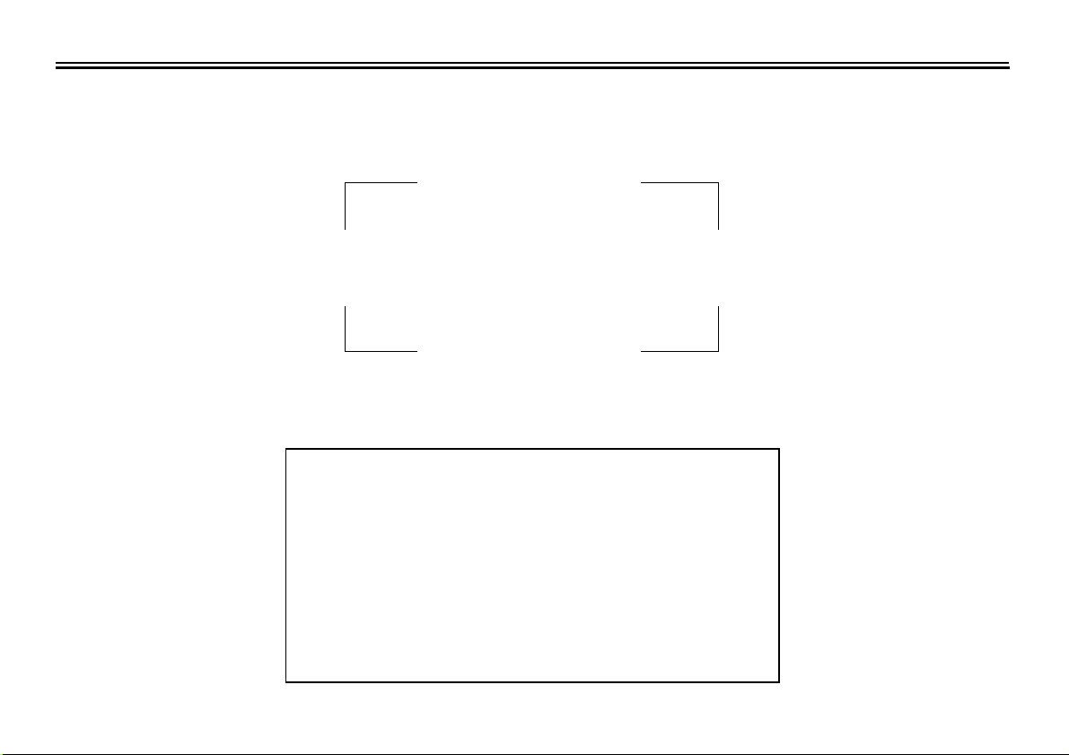
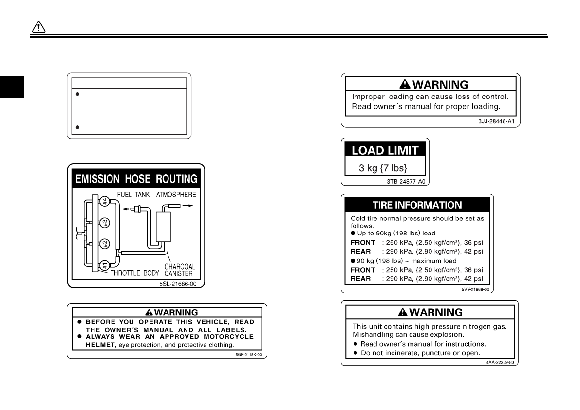
Location of important labels
Please read the following important labels carefully before operating this vehicle.
SAFETY INFORMATION
EAU10381
1
1-5
SAFETY INFORMATION
1
1
2
California only
CAUTION
Cleaning with alkaline or
acid cleaner, gasoline or
solvent will damage
windshield.
Use neutral detergent.
5JW-00
4
5
6
3
7
1-6
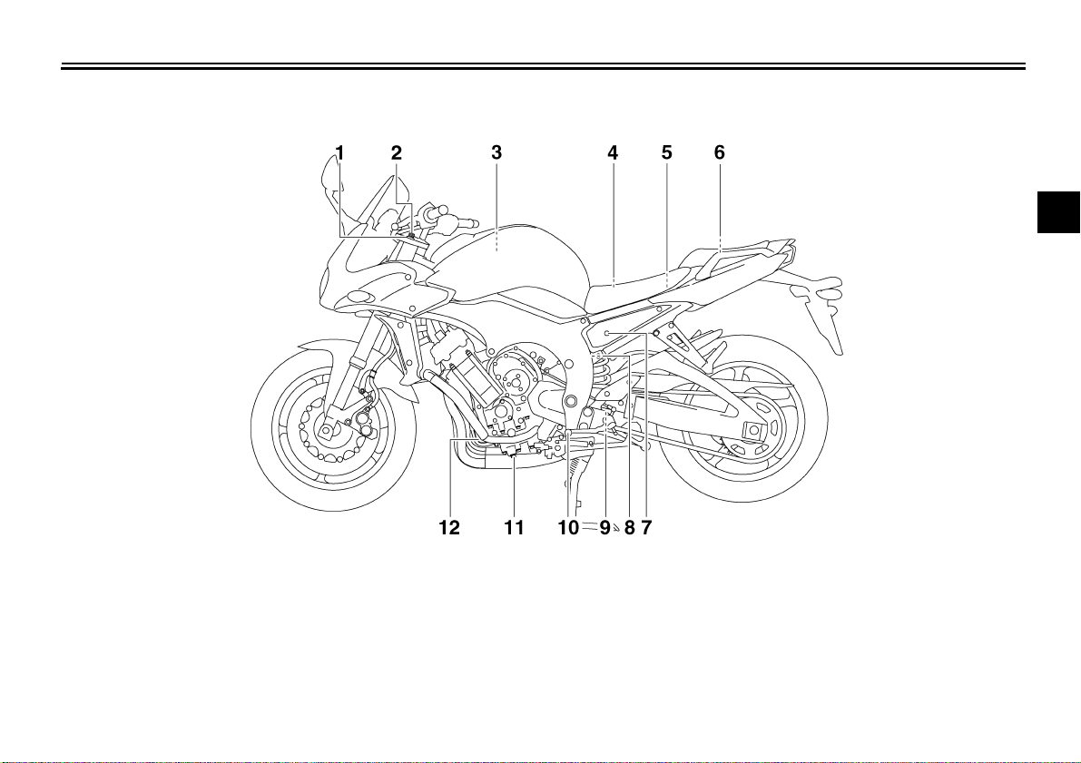
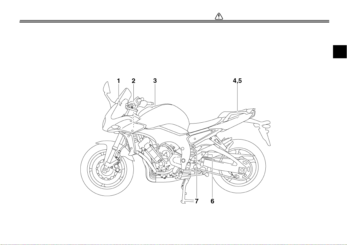
Left view
DESCRIPTION
EAU10410
2
1. Front fork spring preload adjusting bolt (page 3-14)
2. Front fork compression damping force adjusting screw (page 3-14)
3. Air filter element (page 6-15)
4. Main fuse (page 6-32)
5. Fuel injection system fuse (page 6-32)
6. Storage compartment (page 3-14)
7. Passenger seat lock (page 3-12)
8. Shock absorber assembly spring preload adjusting ring (page 3-16)
9. Shock absorber assembly rebound damping force adjusting screw
(page 3-16)
10.Shift pedal (page 3-9)
11.Engine oil drain bolt (page 6-10)
12.Engine oil filter cartridge (page 6-10)
2-1
DESCRIPTION
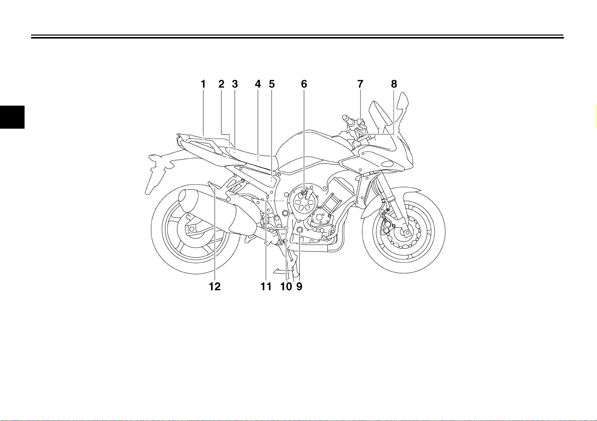
Right view
2
EAU10420
1. Owner’s tool kit (page 6-1)
2. Rider seat lock lever (page 3-12)
3. Fuse box (page 6-32)
4. Battery (page 6-30)
5. Rear brake fluid reservoir (page 6-23)
6. Engine oil filler cap (page 6-10)
7. Front brake fluid reservoir (page 6-23)
8. Front fork rebound damping force adjusting screw (page 3-14)
9. Engine oil level check window (page 6-10)
10.Brake pedal (page 3-10)
11.Coolant reservoir (page 6-13)
12.Luggage strap holder (page 3-18)
2-2
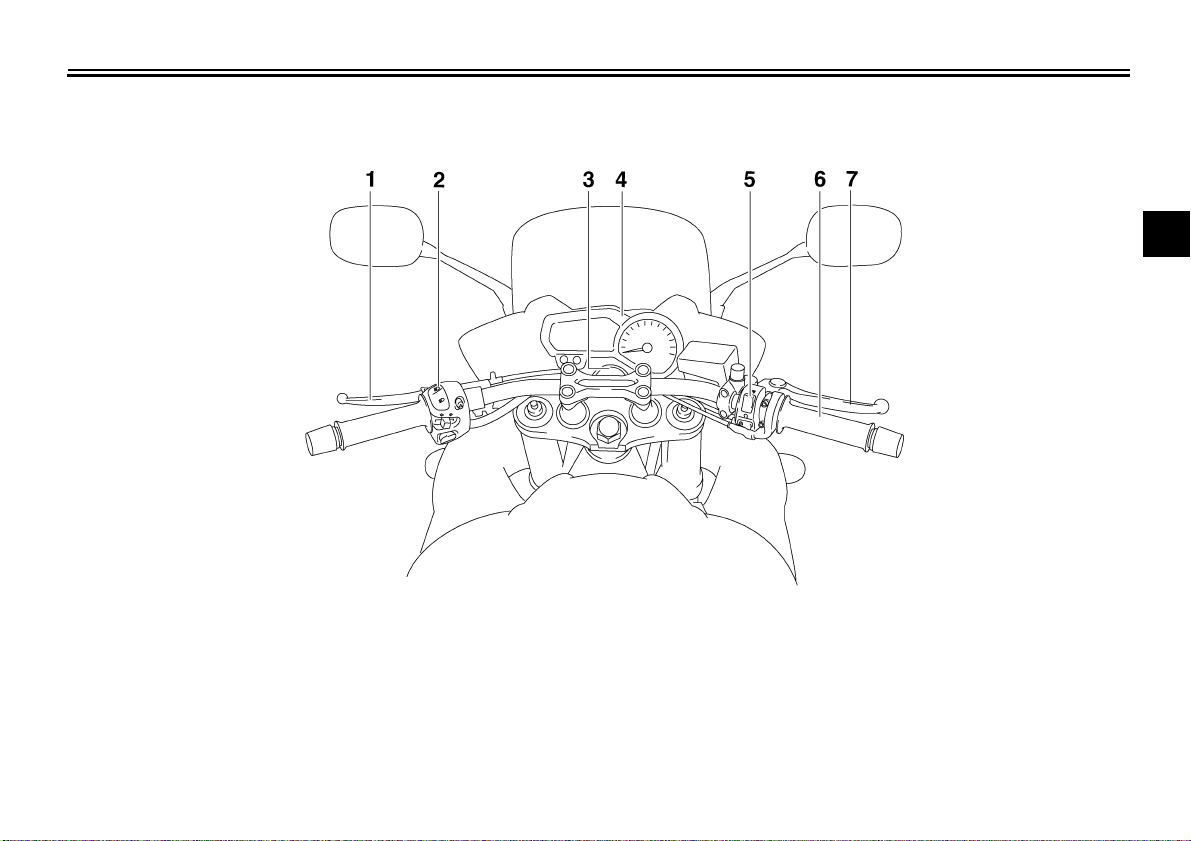
Controls and instruments
1. Clutch lever (page 3-9)
2. Left handlebar switches (page 3-8)
3. Main switch/steering lock (page 3-1)
4. Multi-function meter unit (page 3-4)
5. Right handlebar switches (page 3-8)
6. Throttle grip (page 6-17)
7. Brake lever (page 3-10)
DESCRIPTION
EAU10430
2
2-3
INSTRUMENT AND CONTROL FUNCTIONS
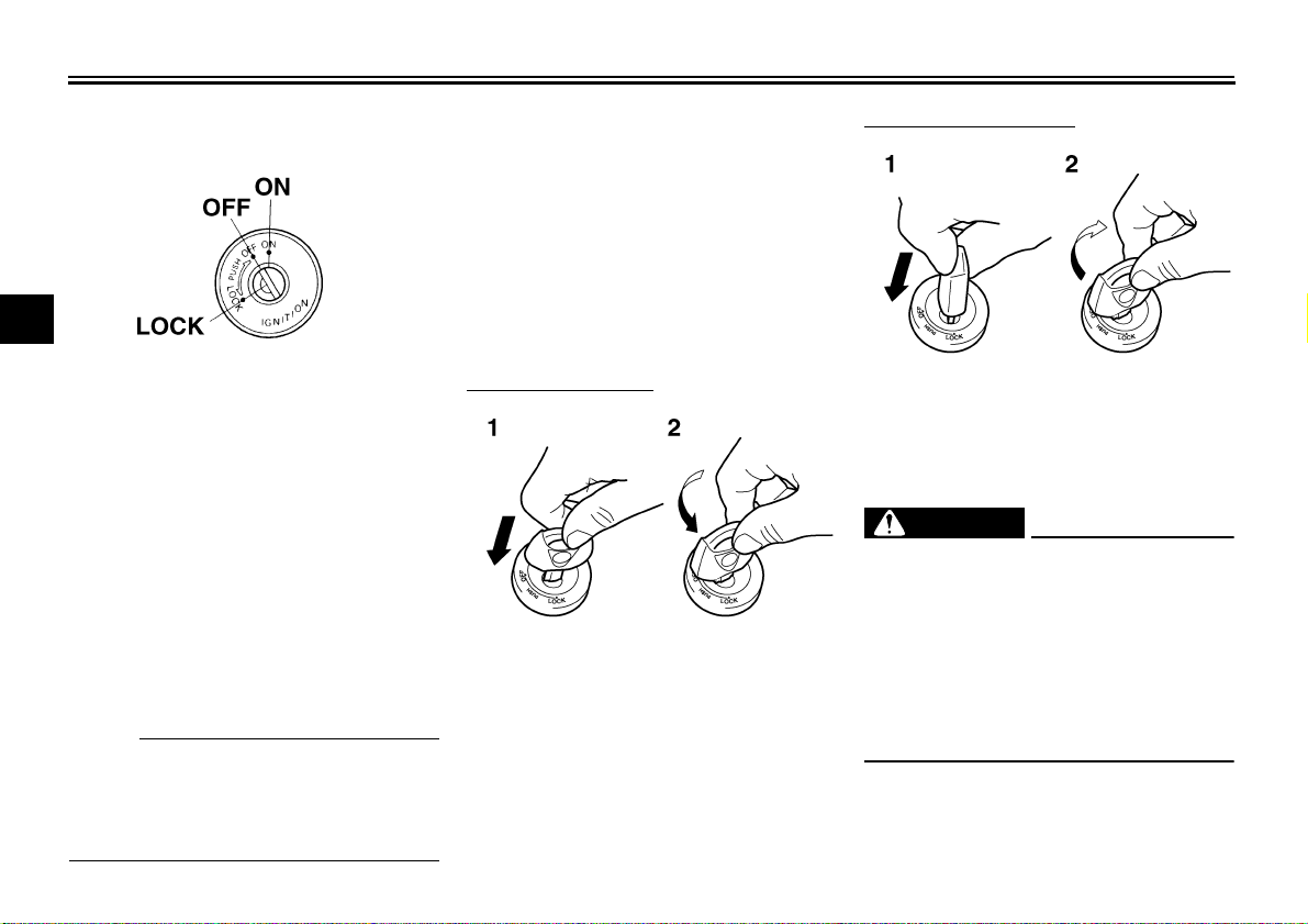
Main switch/steering lock
3
The main switch/steering lock controls
the ignition and lighting systems, and is
used to lock the steering. The various
positions are described below.
ON
All electrical circuits are supplied with
power, and the meter lighting, taillight,
license plate light and position lights
come on, and the engine can be started. The key cannot be removed.
NOTE:
The headlights come on automatically
when the engine is started and stay on
until the key is turned to “OFF”, even if
the engine stalls.
EAU10460
EAU26900
OFF
EAU10660
All electrical systems are off. The key
can be removed.
EAU10680
LOCK
The steering is locked, and all electrical
systems are off. The key can be removed.
To lock the steering
1. Push.
2. Turn.
1. Turn the handlebars all the way to
the left.
2. Push the key in from the “OFF” position, and then turn it to “LOCK”
while still pushing it.
3. Remove the key.
To unlock the steering
1. Push.
2. Turn.
Push the key in, and then turn it to
“OFF” while still pushing it.
EWA10060
WARNING
Never turn the key to “OFF” or
“LOCK” while the vehicle is moving,
otherwise the electrical systems will
be switched off, which may result in
loss of control or an accident. Make
sure that the vehicle is stopped before turning the key to “OFF” or
“LOCK”.
3-1
INSTRUMENT AND CONTROL FUNCTIONS
EAU11003
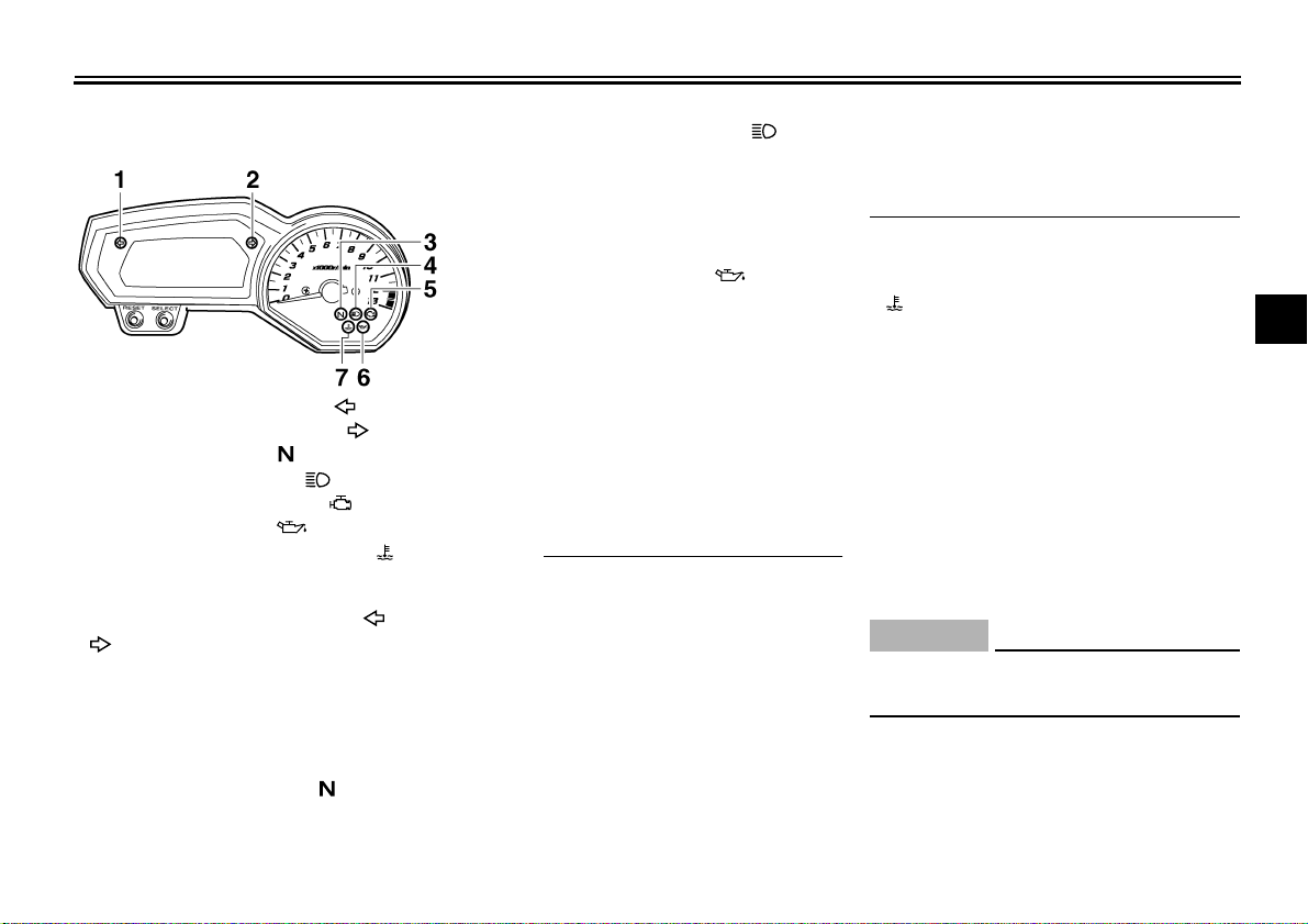
Indicator and warning lights
1. Left turn signal indicator light “”
2. Right turn signal indicator light “”
3. Neutral indicator light “”
4. High beam indicator light “”
5. Engine trouble warning light “”
6. Oil level warning light “”
7. Coolant temperature warning light “”
EAU11030
Turn signal indicator lights “” and
“”
The corresponding indicator light flashes when the turn signal switch is
pushed to the left or right.
EAU11060
Neutral indicator light “”
This indicator light comes on when the
transmission is in the neutral position.
High beam indicator light “”
EAU11080
This indicator light comes on when the
high beam of the headlight is switched
on.
EAU11250
Oil level warning light “”
This warning light comes on when the
engine oil level is low.
The electrical circuit of the warning light
can be checked by turning the key to
“ON”.
If the warning light does not come on
for a few seconds, then go off, have a
Yamaha dealer check the electrical circuit.
NOTE:
● Even if the oil level is sufficient, the
warning light may flicker when
riding on a slope or during sudden
acceleration or deceleration, but
this is not a malfunction.
● This model is also equipped with a
self-diagnosis device for the oil
level detection circuit. If the oil level detection circuit is defective, the
following cycle will be repeated until the malfunction is corrected: The
oil level warning light will flash ten
times, then go off for 2.5 seconds.
If this occurs, have a Yamaha
dealer check the vehicle.
EAU11423
Coolant temperature warning light
“”
This warning light comes on when the
engine overheats. When this occurs,
stop the engine immediately and allow
the engine to cool.
The electrical circuit of the warning light
can be checked by turning the key to
“ON”.
If the warning light does not come on
for a few seconds, then go off, have a
Yamaha dealer check the electrical circuit.
ECA10020
CAUTION:
Do not operate the engine if it is
overheated.
3
3-2
INSTRUMENT AND CONTROL FUNCTIONS
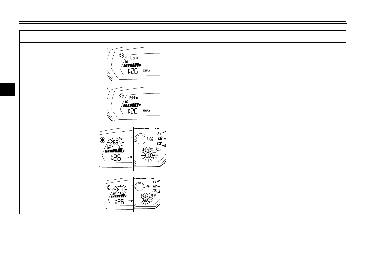
Coolant
temperature
Under 39 °C
(Under 103 °F)
Display Conditions What to do
Message “Lo” is displayed. OK. Go ahead with riding.
3
40–116 °C
(104–242 °F)
117–139 °C
(243–283 °F)
Above 140 °C
(Above 284 °F)
Temperature is displayed. OK. Go ahead with riding.
Temperature display flashes.
Warning light comes on.
Message “HI” flashes.
Warning light comes on.
Stop the vehicle and allow it to idle until
the coolant temperature goes down.
If the temperature does not go down,
stop the engine. (See page 6-39.)
Stop the engine and allow it to cool.
(See page 6-39.)
3-3
INSTRUMENT AND CONTROL FUNCTIONS
Engine trouble warning light “”
EAU11530
This warning light comes on or flashes
when an electrical circuit monitoring the
engine is defective. When this occurs,
have a Yamaha dealer check the selfdiagnosis system. (See page 3-4 for an
explanation of the self-diagnosis device.)
The electrical circuit of the warning light
can be checked by turning the key to
“ON”. If the warning light does not come
on for a few seconds, then go off, have
a Yamaha dealer check the electrical
circuit.
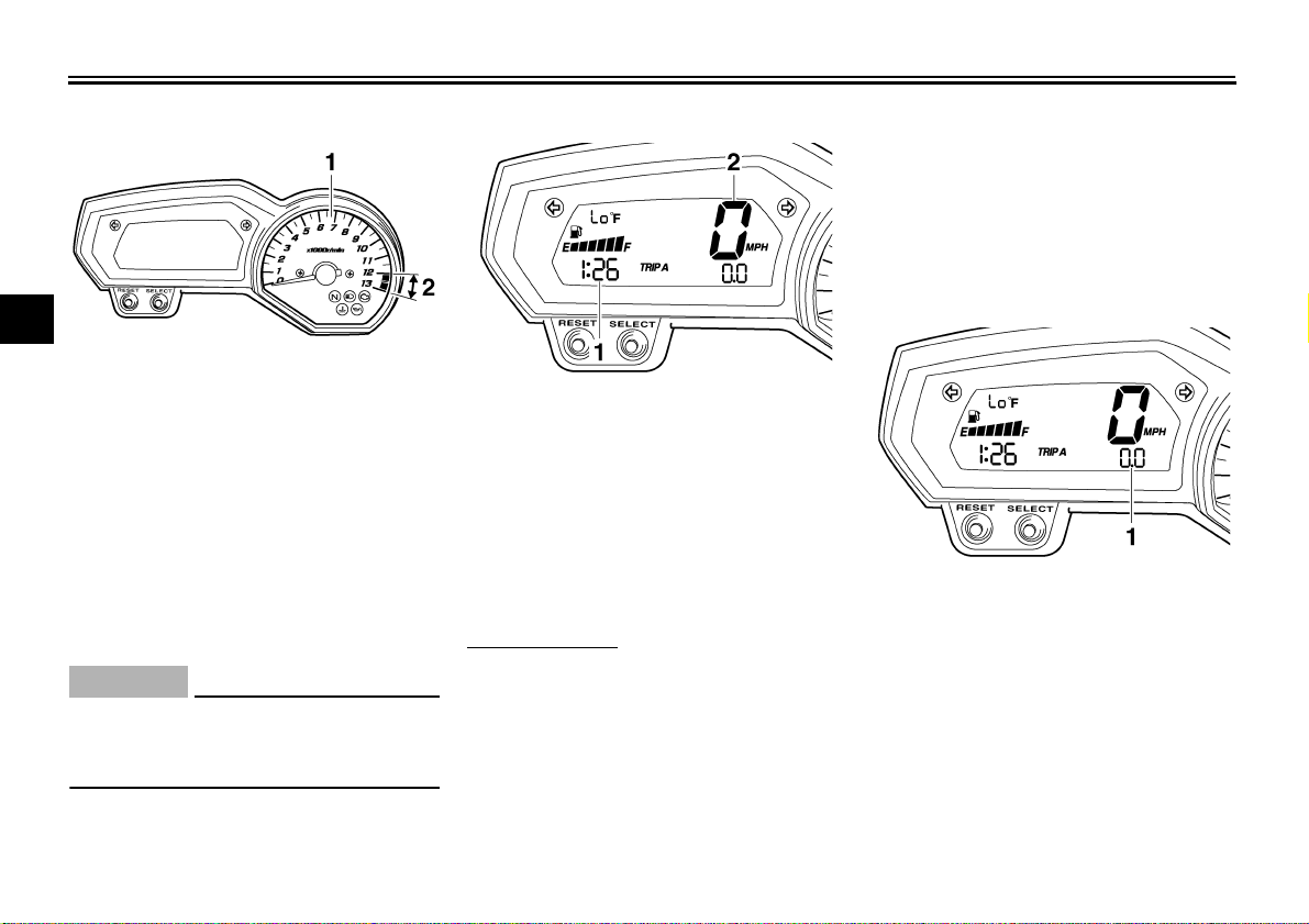
EAU40170
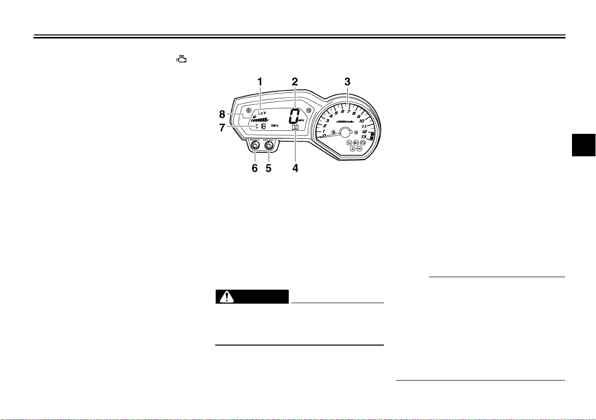
Multi-function meter unit
1. Coolant temperature display/air intake temperature display
2. Speedometer
3. Tachometer
4. Odometer/tripmeter/fuel reserve tripmeter
5. “SELECT” button
6. “RESET” button
7. Clock
8. Fuel meter
EWA12421
WARNING
Be sure to stop the vehicle before
making any setting changes to the
multi-function meter unit.
The multi-function meter unit is
equipped with the following:
● a speedometer (which shows the
riding speed)
3-4
● a tachometer (which shows engine
speed)
● an odometer (which shows the to-
tal distance traveled)
● two tripmeters (which show the
distance traveled since they were
last set to zero)
● a fuel reserve tripmeter (which
shows the distance traveled since
the left segment of the fuel meter
started flashing)
● a clock
● a fuel meter
● a coolant temperature display
● an air intake temperature display
● a self-diagnosis device
● an LCD and tachometer bright-
ness control mode
NOTE:
● Be sure to turn the key to “ON” be-
fore using the “SELECT” and “RE-
SET” buttons.
● To switch the speedometer and
odometer/tripmeter displays between kilometers and miles, press
the “SELECT” button for at least
one second.
3
INSTRUMENT AND CONTROL FUNCTIONS
Tachometer
3
1. Tachometer
2. Tachometer red zone
The electric tachometer allows the rider
to monitor the engine speed and keep it
within the ideal power range.
When the key is turned to “ON”, the tachometer needle will sweep once
across the r/min range and then return
to zero r/min in order to test the electrical circuit.
CAUTION:
Do not operate the engine in the tachometer red zone.
Red zone: 12000 r/min and above
ECA10031
Clock
1. Clock
2. Speedometer
The clock displays when the key is
turned to “ON”. In addition, the clock
can be displayed for 10 seconds by
pushing the “SELECT” button when the
main switch is in the “OFF” or “LOCK”
position.
To set the clock
1. Turn the key to “ON”.
2. Push the “SELECT” button and
“RESET” button together for at
least two seconds.
3. When the hour digits start flashing,
push the “RESET” button to set the
hours.
3-5
4. Push the “SELECT” button, and
the minute digits will start flashing.
5. Push the “RESET” button to set
the minutes.
6. Push the “SELECT” button and
then release it to start the clock.
Odometer and tripmeter modes
1. Odometer/tripmeter/fuel reserve tripmeter
Push the “SELECT” button to switch
the display between the odometer
mode “ODO” and the tripmeter modes
“TRIP A” and “TRIP B” in the following
order:
TRIP A → TRIP B → ODO → TRIP A
When the fuel amount in the fuel tank
decreases to 3.4 L (0.90 US gal) (0.75
Imp.gal), the left segment of the fuel
meter will start flashing, and the odom-
INSTRUMENT AND CONTROL FUNCTIONS
eter display will automatically change to
the fuel reserve tripmeter mode “F-
TRIP” and start counting the distance
traveled from that point. In that case,
push the “SELECT” button to switch the
display between the various tripmeter
and odometer modes in the following
order:
F-TRIP → TRIP A → TRIP B → ODO
→ F-TRIP
To reset a tripmeter, select it by pushing the “SELECT” button, and then
push the “RESET” button for at least
one second. If you do not reset the fuel
reserve tripmeter manually, it will reset
itself automatically and the display will
return to the prior mode after refueling
and traveling 5 km (3 mi).
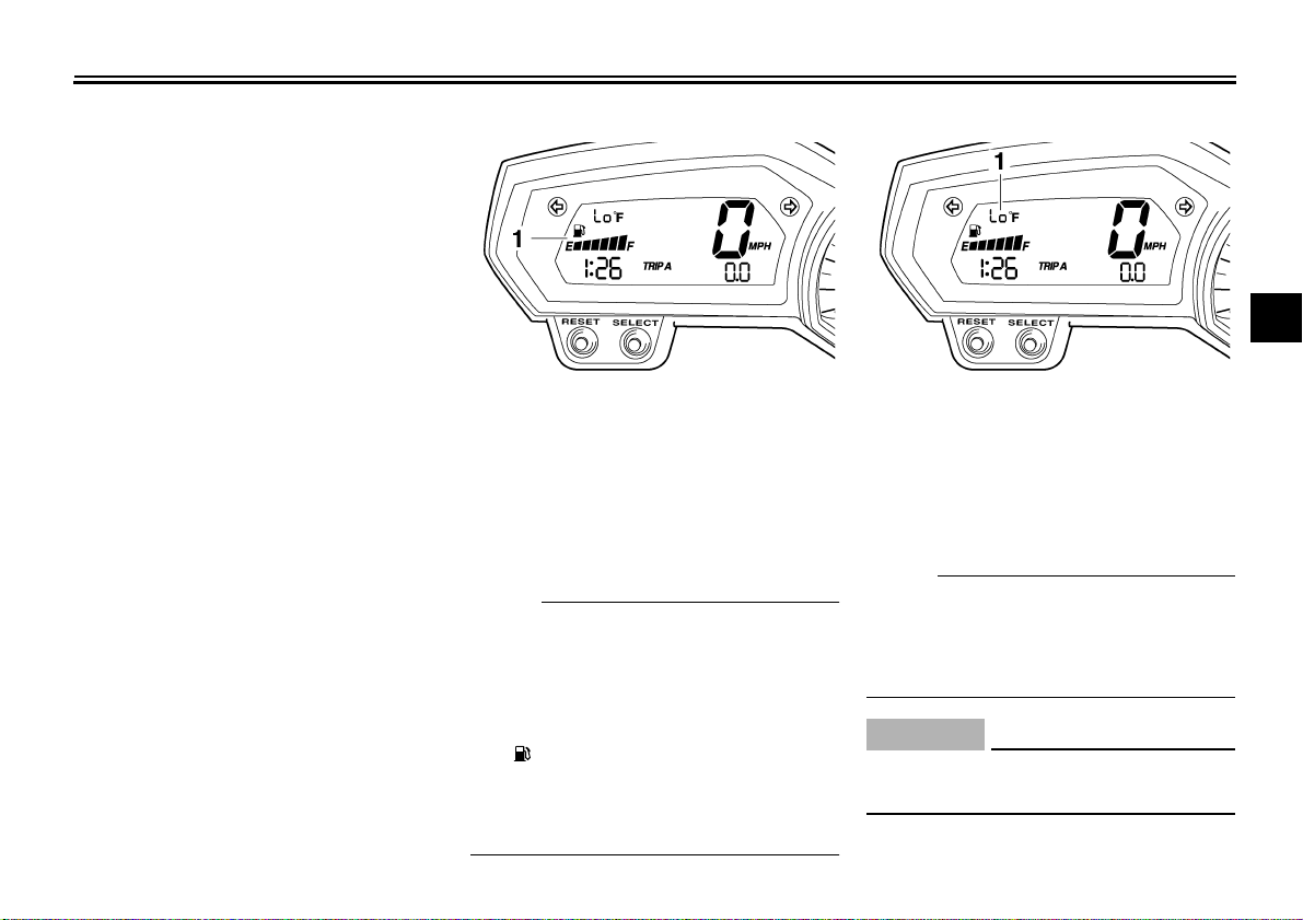
Fuel meter
1. Fuel meter 1. Coolant temperature display
The fuel meter indicates the amount of
fuel in the fuel tank. The display segments of the fuel meter disappear towards “E” (Empty) as the fuel level
decreases. When only one segment is
left near “E”, refuel as soon as possible.
NOTE:
This fuel meter is equipped with a selfdiagnosis system. If the electrical circuit
is defective, the following cycle will be
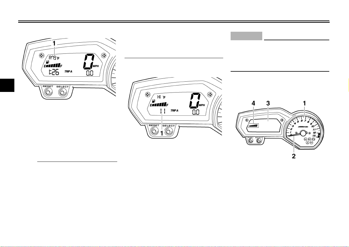
Coolant temperature mode
The coolant temperature display indicates the temperature of the coolant.
Push the “RESET” button to switch the
coolant temperature display to the air
intake temperature display.
NOTE:
When the coolant temperature display
is selected, “C” is displayed for one
second, and then the coolant tempera-
ture is displayed.
repeated until the malfunction is corrected:“E” (Empty),“F” (Full) and sym-
bol “” will flash eight times, then go off
for approximately 3 seconds. If this occurs, have a Yamaha dealer check the
CAUTION:
Do not operate the engine if it is
overheated.
electrical circuit.
3
ECA10020
3-6
INSTRUMENT AND CONTROL FUNCTIONS
Air intake temperature mode
3
1. Air intake temperature display
The air intake temperature display indicates the temperature of the air drawn
into the air filter case. Push the “RE-
SET” button to switch the coolant temperature display to the air intake
temperature display.
NOTE:
● Even if the air intake temperature
is set to be displayed, the coolant
temperature warning light comes
on when the engine overheats.
● When the key is turned to “ON”,
the coolant temperature is automatically displayed, even if the air
intake temperature was displayed
prior to turning the key to “OFF”.
● When the air intake temperature
display is selected, “A” is displayed
for one second, and then the air intake temperature is displayed.
Self-diagnosis device
1. Error code display
This model is equipped with a self-diagnosis device for various electrical circuits.
If any of those circuits are defective, the
engine trouble warning light will come
on, and then the display will indicate a
two-digit error code (e.g., 11, 12, 13).
If the display indicates any error codes,
note the code number, and then have a
Yamaha dealer check the vehicle.
ECA11590
CAUTION:
If the display indicates an error
code, the vehicle should be checked
as soon as possible in order to avoid
engine damage.
LCD and tachometer brightness
control mode
1. Tachometer panel
2. Tachometer needle
3. LCD
4. Brightness level
This function allows you to adjust the
brightness of the LCD and the tachometer panel and needle to suit the outside lighting conditions.
3-7
INSTRUMENT AND CONTROL FUNCTIONS
To set the brightness
1. Turn the key to “OFF”.
2. Push and hold the “SELECT” button.
3. Turn the key to “ON”, and then re-
lease the “SELECT” button after
five seconds.
4. Push the “RESET” button to select
the desired brightness level.
5. Push the “SELECT” button to confirm the selected brightness level.
The display will return to the odometer or tripmeter mode.
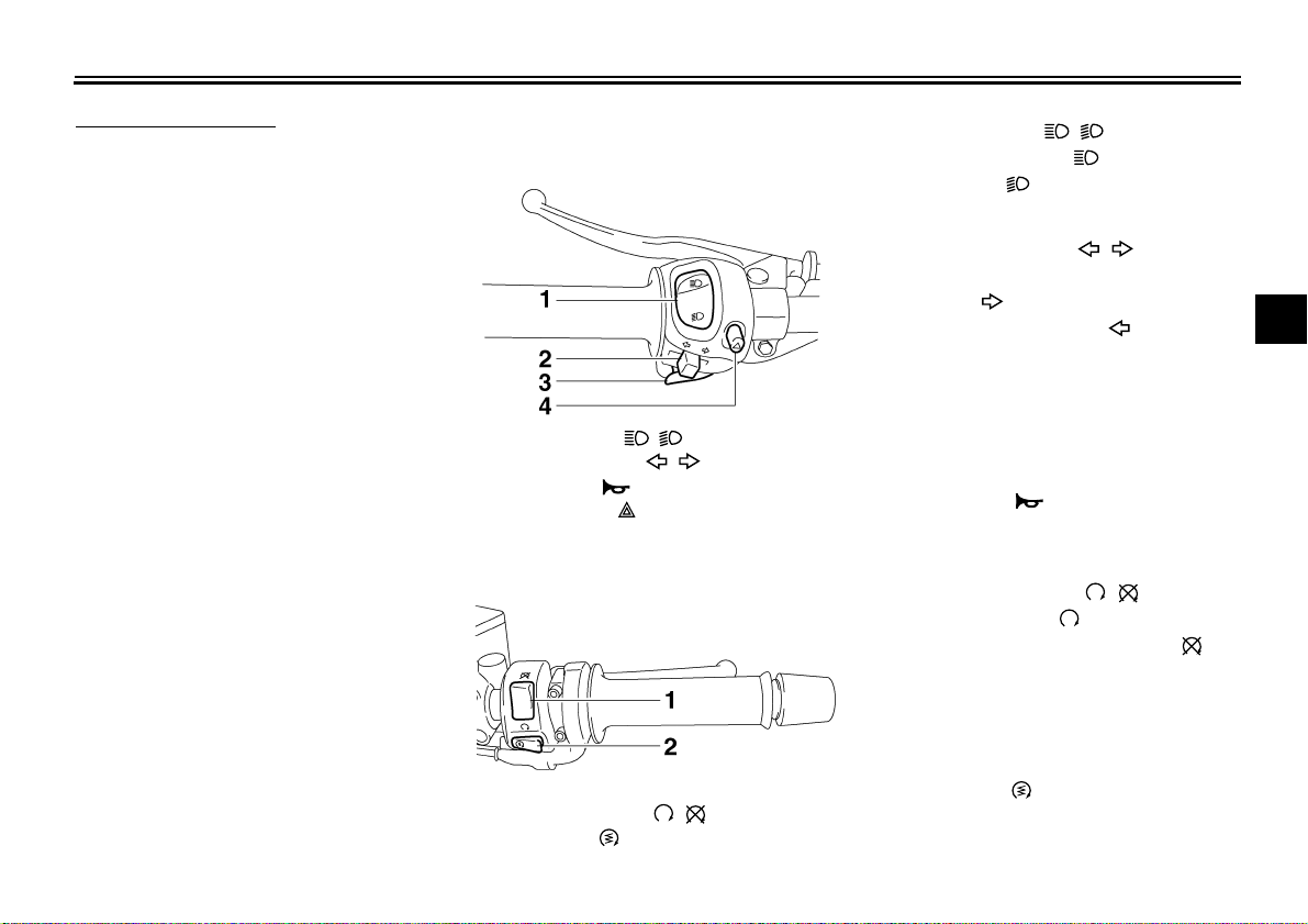
Handlebar switches
Left
1. Dimmer switch “ / ”
2. Turn signal switch “ / ”
3. Horn switch “”
4. Hazard switch “”
Right
EAU12344
Dimmer switch “ / ”
EAU12400
Set this switch to “” for the high
beam and to “” for the low beam.
EAU12460
Turn signal switch “ / ”
To signal a right-hand turn, push this
switch to “”. To signal a left-hand
turn, push this switch to “”. When re-
leased, the switch returns to the center
position. To cancel the turn signal
lights, push the switch in after it has returned to the center position.
EAU12500
Horn switch “”
Press this switch to sound the horn.
EAU12660
Engine stop switch “ / ”
Set this switch to “” before starting
the engine. Set this switch to “” to
stop the engine in case of an emergency, such as when the vehicle overturns
or when the throttle cable is stuck.
3
1. Engine stop switch “ / ”
2. Start switch “”
3-8
Start switch “”
EAU12710
Push this switch to crank the engine
with the starter.
INSTRUMENT AND CONTROL FUNCTIONS
CAUTION:
See page 5-1 for starting instructions prior to starting the engine.
Hazard switch “”
With the key in the “ON” position, turn
3
this switch to “” to turn on the hazard
lights (simultaneous flashing of all turn
signal lights).
The hazard lights are used in case of
an emergency or to warn other drivers
when your vehicle is stopped where it
might be a traffic hazard.
CAUTION:
Do not use the hazard lights for an
extended length of time with the engine not running, otherwise the battery may discharge.
ECA10050
EAU12764
ECA10061
EAU12820
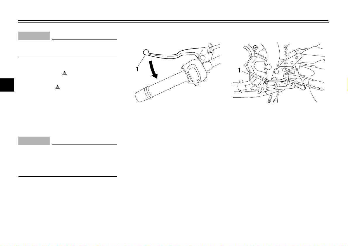
Clutch lever
1. Clutch lever 1. Shift pedal
The clutch lever is located at the left
handlebar grip. To disengage the
clutch, pull the lever toward the handlebar grip. To engage the clutch, release
the lever. The lever should be pulled
rapidly and released slowly for smooth
Shift pedal
The shift pedal is located on the left
side of the engine and is used in combination with the clutch lever when
shifting the gears of the 6-speed constant-mesh transmission equipped on
this motorcycle.
clutch operation.
The clutch lever is equipped with a
clutch switch, which is part of the ignition circuit cut-off system. (See page
3-19.)
EAU12870
3-9
INSTRUMENT AND CONTROL FUNCTIONS
EAU26822
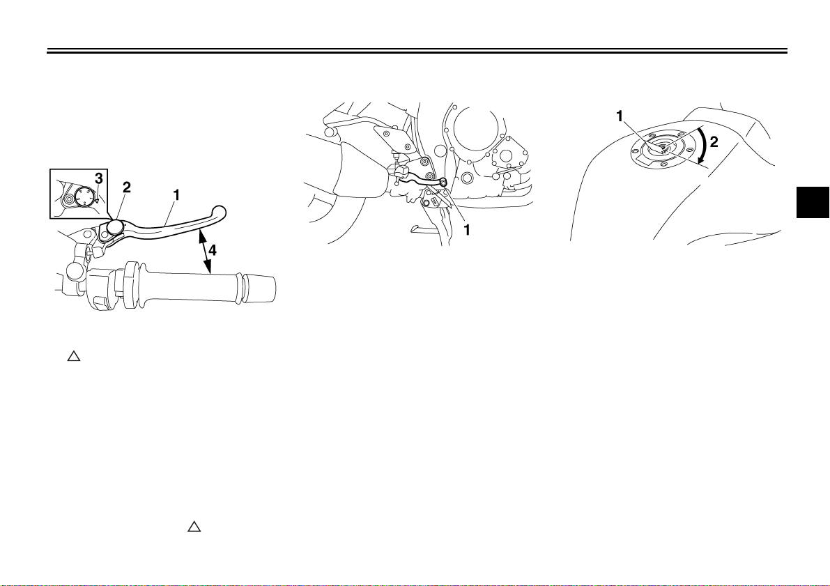
Brake lever
The brake lever is located at the right
handlebar grip. To apply the front
brake, pull the lever toward the handlebar grip.
1. Brake lever
2. Brake lever position adjusting dial
3. “” mark
4. Distance between brake lever and handlebar
grip
The brake lever is equipped with a position adjusting dial. To adjust the distance between the brake lever and the
handlebar grip, turn the adjusting dial
while holding the lever pushed away
from the handlebar grip. Make sure that
the appropriate setting on the adjusting
dial is aligned with the “” mark on the
brake lever.
EAU12941
Brake pedal
1. Brake pedal 1. Fuel tank cap lock cover
The brake pedal is on the right side of
the motorcycle. To apply the rear
brake, press down on the brake pedal.
Fuel tank cap
2. Unlock.
To open the fuel tank cap
Open the fuel tank cap lock cover, insert the key into the lock, and then turn
it 1/4 turn clockwise. The lock will be released and the fuel tank cap can be
opened.
To close the fuel tank cap
1. Push the fuel tank cap into position
with the key inserted in the lock.
2. Turn the key counterclockwise to
the original position, remove it, and
then close the lock cover.
3-10
EAU13070
3
INSTRUMENT AND CONTROL FUNCTIONS
NOTE:
The fuel tank cap cannot be closed unless the key is in the lock. In addition,
the key cannot be removed if the cap is
not properly closed and locked.
WARNING
3
Make sure that the fuel tank cap is
properly closed before riding.
EWA11090
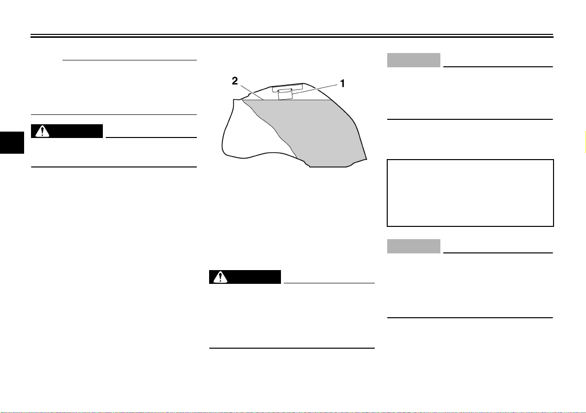
EAU13220
Fuel
1. Fuel tank filler tube
2. Fuel level
Make sure that there is sufficient fuel in
the tank. When refueling, be sure to insert the pump nozzle into the fuel tank
filler hole and to fill the tank to the bottom of the filler tube as shown.
EWA10880
WARNING
● Do not overfill the fuel tank, oth-
erwise it may overflow when the
fuel warms up and expands.
● Avoid spilling fuel on the hot en-
gine.
ECA10070
CAUTION:
Immediately wipe off spilled fuel
with a clean, dry, soft cloth, since
fuel may deteriorate painted surfaces or plastic parts.
EAU13300
Recommended fuel:
UNLEADED GASOLINE ONLY
Fuel tank capacity:
18.0 L (4.76 US gal) (3.96 Imp.gal)
Fuel reserve amount:
3.4 L (0.90 US gal) (0.75 Imp.gal)
ECA11400
CAUTION:
Use only unleaded gasoline. The use
of leaded gasoline will cause severe
damage to internal engine parts,
such as the valves and piston rings,
as well as to the exhaust system.
Your Yamaha engine has been designed to use regular unleaded gasoline with a pump octane number
[(R+M)/2] of 86 or higher, or a research
octane number of 91 or higher. If
3-11
INSTRUMENT AND CONTROL FUNCTIONS
knocking (or pinging) occurs, use a
gasoline of a different brand or premium unleaded fuel. Use of unleaded fuel
will extend spark plug life and reduce
maintenance costs.
Gasohol
There are two types of gasohol: gasohol containing ethanol and that containing methanol. Gasohol containing
ethanol can be used if the ethanol content does not exceed 10%. Gasohol
containing methanol is not recommended by Yamaha because it can
cause damage to the fuel system or vehicle performance problems.
EAU13441
Catalytic converter
This vehicle is equipped with catalytic
converters in the exhaust system.
EWA10860
WARNING
The exhaust system is hot after operation. Make sure that the exhaust
system has cooled down before doing any maintenance work.
ECA10700
CAUTION:
The following precautions must be
observed to prevent a fire hazard or
other damages.
● Use only unleaded gasoline.
The use of leaded gasoline will
cause unrepairable damage to
the catalytic converter.
● Never park the vehicle near pos-
sible fire hazards such as grass
or other materials that easily
burn.
● Do not allow the engine to idle
too long.
EAU39321
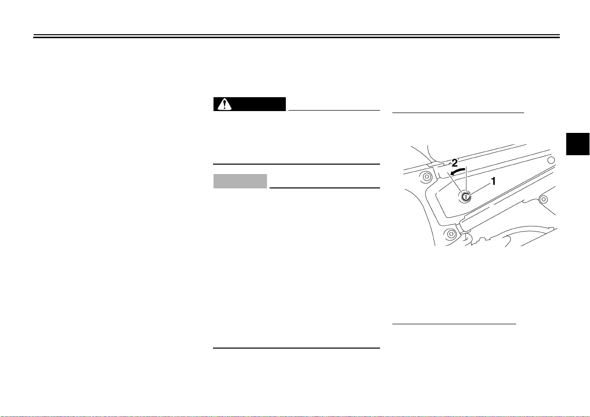
Seats
Passenger seat
To remove the passenger seat
1. Insert the key into the seat lock,
and then turn it counterclockwise.
3
1. Passenger seat lock
2. Unlock.
2. Pull the passenger seat forward,
and then lift it up.
To install the passenger seat
1. Place the passenger seat in the
original position, and then push the
rear of the seat down to lock it in
place.
3-12
INSTRUMENT AND CONTROL FUNCTIONS
3
NOTE:
Make sure that the seats are properly
secured before riding.
2. Remove the key.
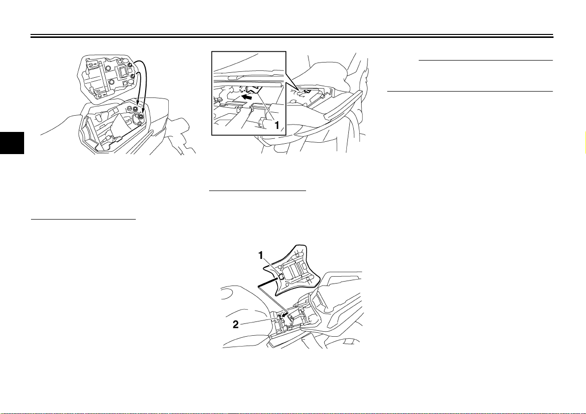
Rider seat
To remove the rider seat
1. Remove the passenger seat.
2. Push the rider seat lock lever, located under the back of the rider
seat, to the left as shown, and then
pull the seat off.
1. Rider seat lock lever
To install the rider seat
1. Insert the projection on the front of
the rider seat into the seat holder
as shown, and then push the rear
of the seat down to lock it in place.
1. Projection
2. Seat holder
2. Install the passenger seat.
3-13
Loading...