


 Loading...
POWER AMPLIFIER
OWNER’S MANUAL
BEDIENUNGSANLEITUNG
MODE D’EMPLOI
MANUAL DE INSTRUCCIONES
English
Deutsch
Français
Español
EN
DE
FR
ES
FCC INFORMATION (U.S.A.)
1.IMPORTANT NOTICE: DO NOT MODIFY THIS UNIT!
This product, when installed as indicated in the instructions contained in this manual, meets FCC requirements. Modifications not expressly approved by Yamaha may void your authority, granted by the FCC, to use the product.
2.IMPORTANT: When connecting this product to accessories and/or another product use only high quality shielded cables. Cable/s supplied with this product MUST be used. Follow all installation instructions. Failure to follow instructions could void your FCC authorization to use this product in the USA.
* This applies only to products (XP7000, XP5000) distributed by YAMAHA CORPORATION OF AMERICA. |
(oscillator) |
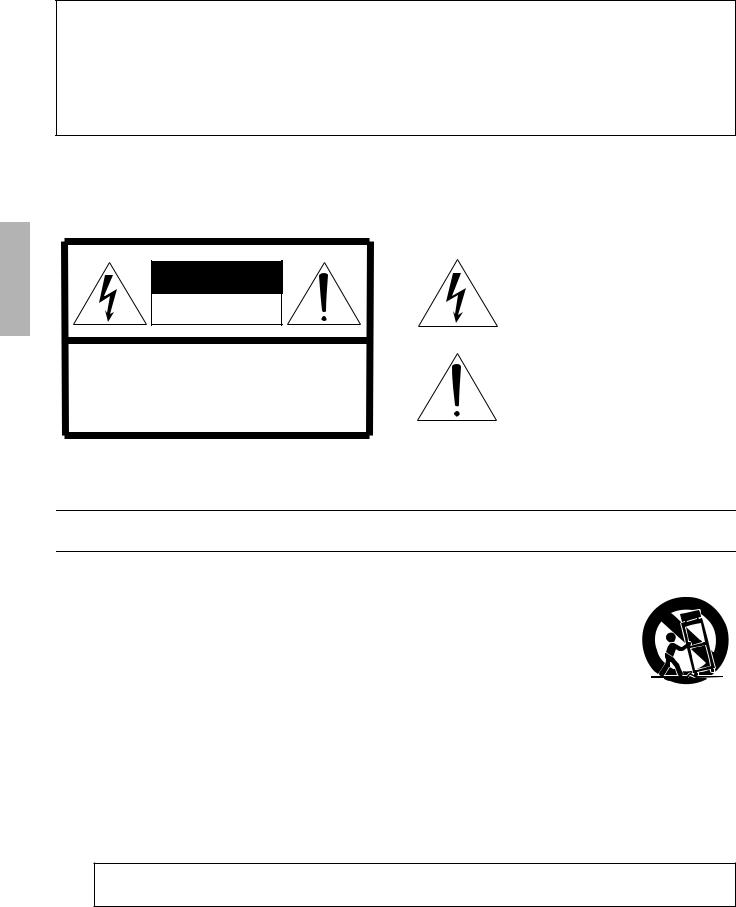
CAUTION
RISK OF ELECTRIC SHOCK
DO NOT OPEN
CAUTION: TO REDUCE THE RISK OF ELECTRIC SHOCK, DO NOT REMOVE COVER (OR BACK). NO USER-SERVICEABLE PARTS INSIDE. REFER SERVICING TO QUALIFIED SERVICE PERSONNEL.
The above warning is located on the top of the unit.
Explanation of Graphical Symbols
The lightning flash with arrowhead symbol within an equilateral triangle is intended to alert the user to the presence of uninsulated “dangerous voltage” within the product’s enclosure that may be of sufficient magnitude to constitute a risk of electric shock to persons.
The exclamation point within an equilateral triangle is intended to alert the user to the presence of important operating and maintenance (servicing) instructions in the literature accompanying the product.
IMPORTANT SAFETY INSTRUCTIONS
1Read these instructions.
2Keep these instructions.
3Heed all warnings.
4Follow all instructions.
5Do not use this apparatus near water.
6Clean only with dry cloth.
7Do not block any ventilation openings. Install in accordance with the manufacturer’s instructions.
8Do not install near any heat sources such as radiators, heat registers, stoves, or other apparatus (including amplifiers) that produce heat.
9Do not defeat the safety purpose of the polarized or grounding-type plug. A polarized plug has two blades with one wider than the other. A grounding type plug has two blades and a third grounding prong. The wide blade or the third prong are provided for your safety. If the provided plug does not fit into your outlet, consult an electrician for replacement of the obsolete outlet.
10Protect the power cord from being walked on or pinched particularly at plugs, convenience receptacles, and the point where they exit from the apparatus.
11Only use attachments/accessories specified by the manufacturer.
12Use only with the cart, stand, tripod, bracket, or table specified
by the manufacturer, or sold with the apparatus. When a cart is used, use caution when moving the cart/apparatus combination to avoid injury from tip-over.
13Unplug this apparatus during
lightning storms or when unused for long periods of time.
14Refer all servicing to qualified service personnel. Servicing is required when the apparatus has been damaged in any way, such as power-supply cord or plug is damaged, liquid has been spilled or objects have fallen into the apparatus, the apparatus has been exposed to rain or moisture, does not operate normally, or has been dropped.
WARNING
TO REDUCE THE RISK OF FIRE OR ELECTRIC SHOCK, DO NOT EXPOSE THIS APPARATUS TO RAIN OR MOISTURE.
(98-6500)
2 XP7000/XP5000/XP3500/XP2500/XP1000 Owner’s Manual

PRECAUTIONS
PLEASE READ CAREFULLY BEFORE PROCEEDING
* Please keep this manual in a safe place for future reference.
 WARNING
Always follow the basic precautions listed below to avoid the possibility of serious injury or even death from electrical shock, short-circuiting, damages, fire or other hazards. These precautions include, but are not limited to, the following:
Power supply/Power cord
•Only use the voltage specified as correct for the device. The required voltage is printed on the name plate of the device.
•Use only the included power cord.
•Do not place the power cord near heat sources such as heaters or radiators, and do not excessively bend or otherwise damage the cord, place heavy objects on it, or place it in a position where anyone could walk on, trip over, or roll anything over it.
•Be sure to connect to an appropriate outlet with a protective grounding connection. Improper grounding can result in electrical shock.
Do not open
•Do not open the device or attempt to disassemble the internal parts or modify them in any way. The device contains no user-serviceable parts. If it should appear to be malfunctioning, discontinue use immediately and have it inspected by qualified Yamaha service personnel.
Water warning
•Do not expose the device to rain, use it near water or in damp or wet conditions, or place containers on it containing liquids which might spill into any openings.
•Never insert or remove an electric plug with wet hands.
If you notice any abnormality
•If the power cord or plug becomes frayed or damaged, or if there is a sudden loss of sound during use of the device, or if any unusual smells or smoke should appear to be caused by it, immediately turn off the power switch, disconnect the electric plug from the outlet, and have the device inspected by qualified Yamaha service personnel.
•If this device should be dropped or damaged, immediately turn off the power switch, disconnect the electric plug from the outlet, and have the device inspected by qualified Yamaha service personnel.
 CAUTION
Always follow the basic precautions listed below to avoid the possibility of physical injury to you or others, or damage to the device or other property. These precautions include, but are not limited to, the following:
Power supply/Power cord
•Remove the electric plug from the outlet when the device is not to be used for extended periods of time, or during electrical storms.
•When removing the electric plug from the device or an outlet, always hold the plug itself and not the cord. Pulling by the cord can damage it.
Location
•Before moving the device, remove all connected cables.
•When setting up the device, make sure that the AC outlet you are using is easily accessible. If some trouble or malfunction occurs, immediately turn off the power switch and disconnect the plug from the outlet.
•Do not use the device in a confined, poorly-ventilated location. If this device is to be used in a small space other than an EIA-standard rack, make sure that there is adequate space between the device and surrounding walls or other devices: at least 5cm at the sides, 10cm behind and 10cm above. Inadequate ventilation can result in overheating, possibly causing damage to the device(s), or even fire.
•Do not expose the device to excessive dust or vibrations, or extreme cold or heat (such as in direct sunlight, near a heater, or in a car during the day) to prevent the possibility of panel disfiguration or damage to the internal components.
•Do not place the device in an unstable position where it might accidentally fall over.
•Do not block the vents. This device has ventilation holes at the front and rear to prevent the internal temperature from becoming too high. In particular, do not place the device on its side or upside down. Inadequate ventilation can result in overheating, possibly causing damage to the device(s), or even fire.
•Do not use the device in the vicinity of a TV, radio, stereo equipment, mobile phone, or other electric devices. Doing so may result in noise, both in the device itself and in the TV or radio next to it.
Connections
•Before connecting the device to other devices, turn off the power for all devices. Before turning the power on or off for all devices, set all volume levels to minimum.
•Use only speaker cables for connecting speakers to the speaker jacks. Use of other types of cables may result in fire.
•Be sure to connect to a properly grounded power source. A ground screw is provided on the rear panel of this device for maximum safety and shock prevention. If the mains outlet is not grounded, be sure to connect the ground screw to a confirmed ground point before plugging the device into the mains. Improper grounding can result in electrical shock.
Maintenance
• Remove the power plug from the AC outlet when cleaning the device.
(5)-4 1/2
XP7000/XP5000/XP3500/XP2500/XP1000 Owner’s Manual 3

Handling caution
•When turning on the AC power in your audio system, always turn on the device LAST, to avoid speaker damage. When turning the power off, the device should be turned off FIRST for the same reason.
•Do not insert your fingers or hands in any gaps or openings on the device (vents, etc.).
•Avoid inserting or dropping foreign objects (paper, plastic, metal, etc.) into any gaps or openings on the device (vents, etc.) If this happens, turn off the power immediately and unplug the power cord from the AC outlet. Then have the device inspected by qualified Yamaha service personnel.
•Do not use the device for a long period of time at a high or uncomfortable volume level, since this can cause permanent hearing loss. If you experience any hearing loss or ringing in the ears, consult a physician.
•Do not rest your weight on the device or place heavy objects on it, and avoid use excessive force on the buttons, switches or connectors.
•Do not use this device for any purpose other than driving loudspeakers.
Yamaha cannot be held responsible for damage caused by improper use or modifications to the device, or data that is lost or destroyed.
Always turn the power off when the device is not in use.
Even when the power switch is in the “STANDBY”, electricity is still flowing to the device at the minimum level. When you are not using the device for a long time, make sure you unplug the power cord from the wall AC outlet.
The performance of components with moving contacts, such as switches, volume controls, and connectors, deteriorates over time. Consult qualified Yamaha service personnel about replacing defective components.
Illustrations in this manual are for explanatory purposes only, and may not match the actual appearance of the product during operation.
Company names and product names used in this Owner’s Manual are trademarks or registered trademarks of their respective owners.
IMPORTANT NOTICE FOR THE UNITED KINGDOM
Connecting the Plug and Cord
WARNING: THIS APPARATUS MUST BE EARTHED
IMPORTANT. The wires in this mains lead are coloured in accordance with the following code:
GREEN-AND-YELLOW : EARTH
BLUE |
: |
NEUTRAL |
BROWN |
: |
LIVE |
As the colours of the wires in the mains lead of this apparatus may not correspond with the coloured markings identifying the terminals in your plug proceed as follows:
The wire which is coloured GREEN-and-YELLOW must be connected to the terminal in the plug which is marked by the letter E or by the safety earth symbol  or colored GREEN or GREEN- and-YELLOW.
The wire which is coloured BLUE must be connected to the terminal which is marked with the letter N or coloured BLACK.
The wire which is coloured BROWN must be connected to the terminal which is marked with the letter L or coloured RED.
• This applies only to products distributed by Yamaha-Kemble Music (U.K.) Ltd. |
(3 wires) |
||
|
|
|
|
|
|
|
|
This  mark indicates a dangerous electrically live terminal. When connecting an external wire to this terminal, it is necessary either to have “a person who have received appropriate guidance on handling” make the connection or to use leads or a cord that have been manufactured in such a way that the connection can be made simply and without problem.
(5)-4 2/2
4 XP7000/XP5000/XP3500/XP2500/XP1000 Owner’s Manual

Introduction
Thank you for purchasing a Yamaha XP7000, XP5000, XP3500, XP2500, XP1000 Series Power Amplifier.
The XP Series of power amplifiers was developed from Yamaha’s wealth of experience in building PA equipment and its tradition of careful attention to every detail of circuit design. These power amplifiers feature high power — thanks to EEEngine (Energy Efficient Engine) technology — and superb quality together with superior reliability and stability, guaranteeing the highest possible audio performance.
Main features include
•Three modes are provided to support a broad range of applications: STEREO mode which can be driven by two independent sources, PARALLEL mode in which a monaural source drives both channels, and BRIDGE mode in which the two internal amps function as a single high-power mono amp.
•Balanced XLR connector and Euroblock connector inputs, and Speakon connector and five-way binding post outputs are provided.
•A high pass filter switch that enables selection of the cutoff frequency (20Hz or 55Hz).
•Signal indicator, clip indicator and sophisticated dB step Volume control are provided for each channel.
•A PROTECTION indicator that shows the state of various protection systems (power on/off detection, output protection, DC detection), a TEMP indicator that indicates heat sink overheating, and a POWER/STANDBY indicator that indicates the power status.
•Variable-speed low-noise fans ensure high reliability.
•The XP7000 enables parallel connection of multiple high-impedance speakers that support 70V line output.
•The XP3500 enables parallel connection of multiple high-impedance speakers that support 100 V line output.
•A MONITOR/REMOTE terminal that allows monitoring or control over the amplifier via a network.
This Owner’s Manual applies to the XP7000, XP5000, XP3500, XP2500, XP1000 power amplifier. In order to take full advantage of your power amplifier and enjoy long and trouble-free operation, please read this Owner’s Manual carefully before using your Power Amplifier.
Contents |
|
Controls and Functions ........................... |
6 |
Front Panel ......................................................... |
6 |
Rear Panel ......................................................... |
7 |
Speaker Connections .............................. |
8 |
Stereo Mode ....................................................... |
8 |
Parallel Mode ..................................................... |
8 |
Bridged Mode |
|
(use as high-power mono amplifier) ................... |
9 |
High-impedance speaker connections .. |
10 |
Connection ............................................. |
11 |
Using a Euroblock connector ........................... |
11 |
Speaker Connection ......................................... |
11 |
Troubleshooting ..................................... |
12 |
Specifications ......................................... |
13 |
General Specifications ..................................... |
13 |
MONITOR/REMOTE PIN layout ...................... |
15 |
Dimensions ...................................................... |
15 |
Block Diagram .................................................. |
16 |
Performance Graphs ........................................ |
18 |
XP7000/XP5000/XP3500/XP2500/XP1000 Owner’s Manual 5

Controls and Functions
■ Front Panel
2
7 |
1 |
3 |
1POWER switch and indicator
Press this to turn the power on or off. The POWER/ STANDBY indicator lights up in green when the power is ON. If the amplifier has been set to STANDBY mode, the indicator is lit in orange.
2TEMP indicator
Lights up red if the heat sink temperature exceeds 85°C (185°F).
3PROTECTION indicator
When the protection system is active, the PROTECT indicator light up in red and the speakers are automatically disconnected from the amplifier’s outputs. The protection system activates in the following situations:
When the amplifier is turned on
The protection system activates for approximately three seconds when the amplifier is turned on. After three seconds, the protection system deactivates automatically and the amplifier is ready for normal operation.
If a DC voltage is detected at the amplifier’s outputs
XP7000/5000: Power shut down and the indicator is not lit.
XP3500/2500/1000: The protection system is active. Once the DC voltage problem is corrected, the protection system deactivates automatically and the amplifier is ready for normal operation.
If the amplifier overheats
When overheating occurs, the PROTECT/MUTE indicator lights. You should immediately turn off the amplifier and allow it time to cool down. See the Precautions section of this Owner’s Manual for ways to prevent the amplifier from overheating.
4CLIP indicator
Lights up red when the output signal distortion on the corresponding channel rises above 1% — indicating that “clipping” has occurred bacause the signal level is too high.
4
5 6 7
* The illustration shows model XP7000.
5SIGNAL indicator
Lights up green when the corresponding channel’s out-
put level exceeds 2 Vrms (equivalent to 1/2 W into an 8 Ω load, or 1 W into a 4 Ω load).
6Volume control knobs
Each control knob adjusts the volume of the corresponding channel, in 31 steps from -∞ dB to 0 dB.
*If you wish to lock in the knob settings, you can fasten the supplied security cover over the knobs so that the settings will not be disturbed.
● How to install the security cover
(1)Use the supplied hex wrench to remove the four attachment screws from the amplifier.
(2)Adjust the security cover to the position of screw holes. Fasten it into place using the same screws.
7Air intakes
The amplifier uses forced-air cooling. The cooling fans draw air in from the front and exhaust it through the rear. Please be sure that you do not block the air intakes or exhaust vents.
*The fans do not come on at initial power-on, but will switch on automatically when the temperature of the heat sink rises above 50°C (122°F). The fan speed will then vary automatically as the temperature changes.
Front |
Rear |
Air |
Air |
intake |
exhaust |
6 XP7000/XP5000/XP3500/XP2500/XP1000 Owner’s Manual
Loading...