


GB
RX-V2600
AV Receiver
Ampli-tuner audio-vidéo
OWNER'S MANUAL MODE D'EMPLOI BEDIENUNGSANLEITUNG BRUKSANVISNING MANUALE DI ISTRUZIONI
MANUAL DE INSTRUCCIONES GEBRUIKSAANWIJZING

CAUTION: READ THIS BEFORE OPERATING YOUR UNIT.
1To assure the finest performance, please read this manual carefully. Keep it in a safe place for future reference.
2Install this sound system in a well ventilated, cool, dry, clean place – away from direct sunlight, heat sources, vibration, dust, moisture, and/or cold. Allow ventilation space of at least 30 cm on the top, 20 cm on the left and right, and 20 cm on the back of this unit.
3Locate this unit away from other electrical appliances, motors, or transformers to avoid humming sounds.
4Do not expose this unit to sudden temperature changes from cold to hot, and do not locate this unit in an environment with high humidity (i.e. a room with a humidifier) to prevent condensation inside this unit, which may cause an electrical shock, fire, damage to this unit, and/or personal injury.
5Avoid installing this unit where foreign objects may fall onto this unit and/or this unit may be exposed to liquid dripping or splashing. On the top of this unit, do not place:
–Other components, as they may cause damage and/or discoloration on the surface of this unit.
–Burning objects (i.e. candles), as they may cause fire, damage to this unit, and/or personal injury.
–Containers with liquid in them, as they may fall and liquid may cause electrical shock to the user and/or damage to this unit.
6Do not cover this unit with a newspaper, tablecloth, curtain, etc. in order not to obstruct heat radiation. If the temperature inside this unit rises, it may cause fire, damage to this unit, and/or personal injury.
7Do not plug in this unit to a wall outlet until all connections are complete.
8Do not operate this unit upside-down. It may overheat, possibly causing damage.
9Do not use force on switches, knobs and/or cords.
10When disconnecting the power cable from the wall outlet, grasp the plug; do not pull the cable.
11Do not clean this unit with chemical solvents; this might damage the finish. Use a clean, dry cloth.
12Only voltage specified on this unit must be used. Using this unit with a higher voltage than specified is dangerous and may cause fire, damage to this unit, and/or personal injury. YAMAHA will not be held responsible for any damage resulting from use of this unit with a voltage other than specified.
13To prevent damage by lightning, keep the power cord and outdoor antennas disconnected from a wall outlet or the unit during a lightning storm.
14Do not attempt to modify or fix this unit. Contact qualified YAMAHA service personnel when any service is needed. The cabinet should never be opened for any reasons.
15When not planning to use this unit for long periods of time (i.e. vacation), disconnect the AC power plug from the wall outlet.
16Install this unit near the AC outlet and where the AC power plug can be reached easily.
17Be sure to read the “TROUBLESHOOTING” section on common operating errors before concluding that this unit is faulty.
18Before moving this unit, press MASTER ON/OFF to release it outward to the OFF position to turn off this unit, the main room, Zone 2 and Zone 3 and then disconnect the AC power plug from the AC wall outlet.
19VOLTAGE SELECTOR (Asia and General models only) The VOLTAGE SELECTOR on the rear panel of this unit must be set for your local main voltage BEFORE plugging into the AC main supply. Voltages are:
Asia model ................................AC 220/230–240 V, 50/60 Hz General model .............AC 110/120/220/230–240 V, 50/60 Hz
WARNING
TO REDUCE THE RISK OF FIRE OR ELECTRIC SHOCK, DO NOT EXPOSE THIS UNIT TO RAIN OR MOISTURE.
As long as this unit is connected to the AC wall outlet, it is not disconnected from the AC power source even if you turn off this unit by MASTER ON/OFF. In this state, this unit is designed to consume a very small quantity of power.
■ For U.K. customers
If the socket outlets in the home are not suitable for the plug supplied with this appliance, it should be cut off and an appropriate 3 pin plug fitted. For details, refer to the instructions described below.
Note
The plug severed from the mains lead must be destroyed, as a plug with bared flexible cord is hazardous if engaged in a live socket outlet.
■ Special Instructions for U.K. Model
IMPORTANT
THE WIRES IN MAINS LEAD ARE COLOURED IN ACCORDANCE WITH THE FOLLOWING CODE:
Blue: NEUTRAL
Brown: LIVE
As the colours of the wires in the mains lead of this apparatus may not correspond with the coloured markings identifying the terminals in your plug, proceed as follows:
The wire which is coloured BLUE must be connected to the terminal which is marked with the letter N or coloured BLACK. The wire which is coloured BROWN must be connected to the terminal which is marked with the letter L or coloured RED.
Making sure that neither core is connected to the earth terminal of the three pin plug.

CONTENTS
INTRODUCTION |
|
FEATURES............................................................. |
2 |
GETTING STARTED............................................ |
3 |
Supplied accessories .................................................. |
3 |
Installing batteries in the remote controls.................. |
4 |
Handling the remote control ...................................... |
5 |
Opening and closing the front panel door.................. |
5 |
CONTROLS AND FUNCTIONS ......................... |
6 |
Front panel................................................................. |
6 |
Remote control........................................................... |
8 |
Zone 2/Zone 3 remote control ................................. |
10 |
Front panel display .................................................. |
11 |
Rear panel ................................................................ |
13 |
PREPARATION |
|
CONNECTIONS .................................................. |
14 |
Before connecting speakers ..................................... |
14 |
Connecting speakers ................................................ |
15 |
Using bi-wire and bi-AMP connections .................. |
19 |
Information on cables and jacks |
|
used for connections............................................ |
20 |
Connecting HDMI components............................... |
23 |
Connecting video components................................. |
24 |
Connecting audio components................................. |
27 |
Connecting the antennas .......................................... |
29 |
Connecting the power cable..................................... |
30 |
Turning on and off this unit ..................................... |
30 |
Setting the speaker impedance................................. |
31 |
AUTO SETUP....................................................... |
32 |
Introduction.............................................................. |
32 |
Optimizer microphone setup.................................... |
32 |
Using AUTO SETUP .............................................. |
33 |
Confirming the results ............................................. |
35 |
BASIC OPERATION |
|
PLAYBACK.......................................................... |
37 |
Basic operations....................................................... |
37 |
Additional operations............................................... |
39 |
RECORDING ....................................................... |
46 |
FM/AM TUNING ................................................. |
47 |
Automatic tuning ..................................................... |
47 |
Manual tuning.......................................................... |
48 |
Automatic preset tuning........................................... |
48 |
Manual preset tuning ............................................... |
50 |
Selecting preset stations........................................... |
51 |
Exchanging preset stations ...................................... |
52 |
Receiving Radio Data System stations .................... |
53 |
Changing the Radio Data System mode .................. |
53 |
PTY SEEK function ................................................ |
54 |
EON function........................................................... |
55 |
SOUND FIELD PROGRAMS |
|
EDITING SOUND FIELD PARAMETERS |
......56 |
What is a sound field? ............................................. |
56 |
Changing parameter settings ................................... |
56 |
SOUND FIELD PROGRAM |
|
DESCRIPTIONS............................................... |
58 |
For movie/video sources.......................................... |
58 |
For music sources .................................................... |
60 |
SOUND FIELD PARAMETER |
|
DESCRIPTIONS............................................... |
61 |
SOUND FIELD PROGRAM |
|
SPEAKER LAYOUTS...................................... |
66 |
ADVANCED OPERATION |
|
SYSTEM OPTIONS ............................................. |
70 |
Changing parameter settings ................................... |
72 |
Input Select .............................................................. |
73 |
Manual Setup (Sound) ............................................. |
76 |
Manual Setup (Video) ............................................. |
80 |
Manual Setup (Basic) .............................................. |
83 |
Manual Setup (Option) ............................................ |
87 |
System Memory....................................................... |
92 |
Language ................................................................. |
93 |
ADVANCED SETUP............................................ |
94 |
Using ADVANCED SETUP ................................... |
94 |
REMOTE CONTROL FEATURES ................... |
96 |
Control area ............................................................. |
96 |
Controlling each component.................................... |
97 |
Setting remote control codes ................................... |
98 |
Using LEARN ....................................................... |
100 |
Using RE-NAME .................................................. |
102 |
Using MACRO ...................................................... |
103 |
Using CLEAR........................................................ |
105 |
ZONE 2/ZONE 3................................................. |
108 |
Connecting the Zone 2 and |
|
Zone 3 components ........................................... |
108 |
Selecting Zone 2 or Zone 3.................................... |
109 |
Controlling Zone 2 and Zone 3.............................. |
110 |
Using the control mode of |
|
Zone 2 and Zone 3............................................. |
111 |
HDMI ................................................................... |
112 |
What is HDMI? ..................................................... |
112 |
Setting the HDMI parameters................................ |
113 |
Basic HDMI operations ......................................... |
113 |
ADDITIONAL INFORMATION |
|
TROUBLESHOOTING ..................................... |
114 |
GLOSSARY......................................................... |
121 |
Audio information ................................................. |
121 |
Video information.................................................. |
124 |
Sound field program information .......................... |
124 |
Parametric equalizer information .......................... |
125 |
SPECIFICATIONS............................................. |
126 |
INTRODUCTION |
|
|
|
|
|
PREPARATION |
|
|
|
|
|
OPERATION |
BASIC |
|
|
|
|
PROGRAMS |
FIELD SOUND |
|
|
|
|
OPERATION |
ADVANCED |
|
|
|
|
INFORMATION |
ADDITIONAL |
|
|
|
|
English |
|
|
|
1

FEATURES
Built-in 7-channel power amplifier
Minimum RMS Output Power (0.04% THD, 20 Hz to 20 kHz, 8 Ω)
Front: 130 W + 130 W Center: 130 W
Surround: 130 W + 130 W Surround Back: 130 W + 130 W
Sound field features
Proprietary YAMAHA technology for the creation of sound fields
THX Select2
Dolby Digital/Dolby Digital EX decoder
DTS/DTS-ES Matrix 6.1, Discrete 6.1, DTS Neo:6 decoder, DTS 96/24
Dolby Pro Logic/Dolby Pro Logic  x decoder
Virtual CINEMA DSP
SILENT CINEMA™
HDMI (High-Definition Multimedia Interface)
HDMI interface for standard, enhanced or high-definition video as well as multi-channel digital audio
Analog video to HDMI digital video up-conversion (composite video ↔ S-video ↔ component video → HDMI digital video) and up-scaling (480i → 480p/ 1080i/720p and 480p → 1080i/720p) capabilities for
monitor out
Sophisticated AM/FM tuner
40-station random access preset tuning
Automatic preset tuning
Preset station shifting capability (preset editing)
Radio Data System
(U.K. and Europe models only)
Radio Data System tuning capability
Other features
YPAO (YAMAHA Parametric Room Acoustic Optimizer) for automatic speaker setup
192-kHz/24-bit D/A converter
GUI (graphical user interface) menus that allow you to optimize this unit to suit your individual audio/video system
GUI display menu language switching capability (English, Japanese, French, German and Spanish)
6 or 8-channel additional input jacks for discrete multi-channel input
Short message function
PURE DIRECT for pure fidelity sound with analog and PCM sources
S-video input/output capability
Component video input/output capability
Analog video I/P conversion from 480i (NTSC) or 576i (PAL) to 480p (NTSC) or 576p (PAL)
Optical and coaxial digital audio signal jacks
Sleep timer
Cinema and music night listening mode
Remote control with preset remote control codes and learning/macro capability
Zone 2/Zone 3 custom installation facility
Zone 2/Zone 3 remote control to control Zone 2 or Zone 3
Zone 2 OSD (on-screen display) capability
•yindicates a tip for your operation.
•Some operations can be performed by using either the buttons on the main unit or on the remote control. In cases when the button names differ between the main unit and the remote control, the button name on the remote control is given in parentheses.
•This manual is printed prior to production. Design and specifications are subject to change in part as a result of improvements, etc. In case of differences between the manual and product, the product has priority.
Manufactured under license from Dolby Laboratories. “Dolby”, “Surround EX”, and the double-D symbol are trademarks of Dolby Laboratories.
“DTS”, “DTS-ES”, “Neo:6” and “DTS 96/24” are trademarks of Digital Theater Systems, Inc.
“HDMI”, the “HDMI” logo and “High-Definition Multimedia Interface” are trademarks or registered trademarks of HDMI Licensing LLC.
“SILENT CINEMA” is a trademark of YAMAHA CORPORATION.
The THX logo is a trademark of THX Ltd. which may be registered in some jurisdictions. All rights reserved.
2
GETTING STARTED
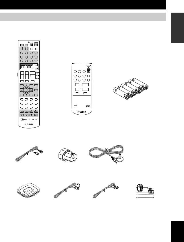
Supplied accessories
Please check that you received all of the following parts.
Remote control
POWER |
POWER |
STANDBY |
POWER |
|
|
|
|
|
|
TV |
AV |
|
|
|
|
|
|
|
|
A |
XMB |
AUDIO SEL |
SLEEP |
|
|
|
|
|
|
PHONO |
TUNER |
CD |
MULTI CH IN |
|
|
|
|
|
|
V-AUX |
CBL/SAT |
MD/TAPE |
CD-R |
Zone 2/Zone 3 |
|||||
DTV |
VCR 1 |
DVR/VCR2 |
DVD |
remote control |
|||||
|
|
|
|
|
|||||
|
|
|
|
|
|
|
|
|
POWER |
|
|
|
|
SELECT |
|
|
|
|
|
|
|
|
|
|
TUNER |
CD |
CD-R |
STANDBY |
|
+ |
+ |
|
+ |
AMP |
1 |
|
2 |
3 |
|
|
|
DTV |
CBL/SAT MD/TAPE |
PHONO |
|||||
|
|
|
|
SOURCE |
|||||
TV VOL |
CH |
VOLUME |
4 |
|
5 |
6 |
ENT |
||
|
|
|
|
|
|
||||
– |
– |
|
– |
TV |
VCR1 |
DVR/VCR2 |
DVD |
V-AUX |
|
|
|
||||||||
|
|
|
|
|
7 |
|
8 |
9 |
0 |
TV MUTE |
TV INPUT |
|
MUTE |
|
|
|
|
|
|
GUI TOP |
PRESET/CH |
EXIT |
PURE DIRECT |
|
+ |
|
+ |
|
|
TITLE |
|
MENU |
|
|
|
|
|||
BAND |
|
SRCH MODE |
|
PRESET |
|
VOLUME |
|||
|
|
|
|
|
|
||||
|
|
|
|
NIGHT |
|
– |
|
– |
|
|
ENTER |
|
|
AUDIO |
|
|
|
||
|
|
A/B/C/D/E-E/CAT. |
|
A/B/C/D/E |
|
|
|
||
|
|
|
|
STRAIGHT |
|
|
|
MUTE |
|
RETURN |
|
DISPLAY |
|
|
|
|
|
|
|
XM MEMORY |
|
|
|
EFFECT |
|
|
|
|
|
STEREO |
MUSIC |
ENTERTAIN |
MOVIE |
|
|
|
|
|
|
1 |
2 |
3 |
|
4 |
|
|
|
|
|
THX |
STANDARD |
SELECT |
EXTD SUR. |
|
|
|
|
|
|
5 |
6 |
7 |
|
8 |
ID1 ID2 |
|
ZONE 2 ZONE 3 |
||
|
|
|
|
|
|
||||
1 MEMORY 2 |
A |
SPEAKERS B |
|
|
|
|
|
||
9 |
0 |
+10 |
ENT. |
|
|
|
|
|
|
FREQ/TEXT |
EON |
MODE |
PTY SEEK START |
|
|
|
|
|
|
REC |
|
|
|
|
|
|
|
|
|
DISC SKIP |
|
|
|
|
|
|
|
|
|
OFF ON |
MACRO LEARN |
CLEAR RE–NAME |
|
|
|
|
|
||
Batteries (x6)
(AAA, LR03)
Power cable |
Speaker terminal |
Optimizer microphone |
|
wrench |
|
|
Indoor FM antenna |
Indoor FM antenna |
|
|
|
|
|
|
|
|
|
(U.S.A., Canada, Asia, |
(Australia, U.K. and |
75-ohm/300-ohm antenna |
|||||||
AM loop antenna |
General, China and |
Europe models) |
||||||||
adapter (U.K. model only) |
||||||||||
Korea models) |
|
|||||||||
|
|
|||||||||
|
|
|
|
|
|
|
|
|
||
|
|
|
|
|
|
|
|
|
|
|
|
|
|
|
|
|
|
|
|
|
|
|
|
|
|
|
|
|
|
|
|
|
INTRODUCTION
English
3
GETTING STARTED
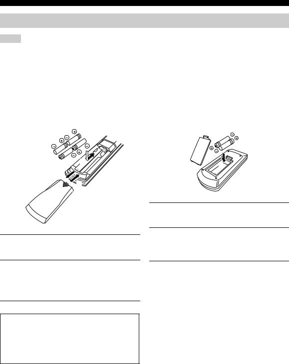
Installing batteries in the remote controls
Notes
•Change all of the batteries if you notice conditions such as the operation range of the remote control decreases, the indicator does not flash, or its light or display window become dim.
•Do not use old batteries together with new ones.
•Do not use different types of batteries (such as alkaline and manganese batteries) together. Read the packaging carefully as these different types of batteries may have the same shape and color.
•We strongly recommend using alkaline batteries.
•If the batteries have leaked, dispose of them immediately. Avoid touching the leaked material or letting it come into contact with clothing, etc. Clean the battery compartment thoroughly before installing new batteries.
•Do not throw away batteries with general house waste; dispose of them correctly in accordance with your local regulations.
■ Installing batteries |
■ Zone 2/Zone 3 remote control |
1
 3
3

 2 1
2 1
3
2
1Press the  part and slide the battery compartment cover off.
1Press the  part and slide the battery compartment cover off.
2Insert four supplied batteries
(AAA, LR03) according to the polarity markings on the inside of the battery compartment.
3Slide the cover back until it snaps into place.
If the remote control is without batteries for more than 2 minutes, or if exhausted batteries remain in the remote control, the contents of the memory may be cleared. When the memory is cleared, insert new batteries, set up the remote control code and program any acquired functions that may have been cleared.
2Insert two supplied batteries (AAA, LR03) according to the polarity markings (+ and –) on the inside of the battery compartment.
3Slide the cover back until it snaps into place.
4
GETTING STARTED
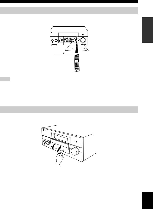
Handling the remote control
The remote control transmits a directional infrared ray.
Be sure to aim the remote control directly at the remote control sensor on the main unit during operation.
Approximately 6 m |
30 |
30 |
|
+ |
+ |
+ |
– |
– |
– |
INTRODUCTION
Notes
•Do not spill water or other liquids on the remote control.
•Do not drop the remote control.
•Do not leave or store the remote control in the following types of conditions:
–places of high humidity, such as near a bath
–places of high temperatures, such as near a heater or stove
–extremely low temperatures
–dusty places
Opening and closing the front panel door
When you want to use the controls behind the front panel door, open the door by gently pressing on the lower part of the panel. Keep the door closed when not using these controls.
To open, press gently on the lower part of the panel.
English
5
|
CONTROLS AND FUNCTIONS |
|
||||||||
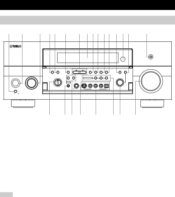
Front panel |
|
|
|
|
|
|
|
|
|
|
1 2 |
3 4 5 6 7 8 9 0 A B C D E |
F |
||||||||
|
|
|
|
|
|
|
|
|
|
PURE DIRECT |
|
|
|
|
|
|
|
|
|
|
VOLUME |
|
AUDIO |
MULTI CH |
|
|
PRESET/ |
PRESET/ |
|
TUNING |
TONE |
|
|
SELECT |
INPUT |
|
A/B/C/D/E |
TUNING |
TUNING |
FM/AM MEMORY MODE |
STRAIGHT CONTROL |
|
|
MAIN ZONE |
INPUT |
|
|
|
|
EDIT |
MAN'L/AUTO FM AUTO/MAN'L |
EFFECT |
|
|
|
|
|
|
|
|
|
|
|
||
|
|
SOURCE/ |
|
SPEAKERS |
|
ZONE ON/OFF |
ZONE CONTROL |
|
|
|
|
DVD REMOTEMD/TAPE |
|
|
MULTI ZONE |
|
|
PROGRAM |
|
||
|
DTV |
|
CD-R |
|
|
|
|
|
|
|
|
CBL/SAT |
|
CD |
A |
B |
|
ZONE 2 ZONE 3 |
|
|
|
|
|
|
|
|
|
|
|
|
||
ON/OFF |
VCR 1 |
|
PHONO YPAO |
SILENT CINEMA |
S VIDEO VIDEO |
L AUDIO R |
OPTICAL |
|
|
|
DVR/ |
|
|
|
|
|
|
|
|
|
|
|
|
TUNER |
|
|
|
|
|
|
|
|
|
VCR 2 |
|
|
|
|
|
|
|
|
|
|
V-AUX |
|
|
|
|
|
|
|
|
|
MASTER |
REC OUT/ZONE 2 |
OPTIMIZER |
|
|
|
|
|
|
||
|
|
|
MIC |
PHONES |
VIDEO/AUX |
|
|
|
||
ON OFF |
|
|
|
|
|
|
|
|
|
|
G |
H I J |
K |
L M |
N |
|
1 MASTER ON/OFF |
|
4 AUDIO SELECT |
|
||
Press inward to the ON position. |
|
Toggles the priority for the type of audio input jack |
|||
• Turns on this unit. |
|
between AUTO, HDMI, COAX/OPT and ANALOG when |
|||
• Turns on the main room. |
|
one component is connected to two or more input jacks on |
|||
• Sets Zone 2 and Zone 3 to the standby mode. |
the rear panel (see page 44). |
|
|||
Press again to release it outward to the OFF position. |
5 MULTI CH INPUT |
|
|||
• Turns off this unit. |
|
|
|||
|
Selects the input source connected to the MULTI CH |
||||
• Turns off the main room, Zone 2 and Zone 3. |
|||||
INPUT jacks. When selected, the MULTI CH INPUT |
|||||
See page 30 for details. |
|
||||
|
source takes priority over the input source selected with |
||||
2 MAIN ZONE ON/OFF |
|
||||
|
the INPUT selector (or the input selector buttons on the |
||||
Turns on this unit only or sets it to the standby mode. |
remote control). |
|
|||
y |
|
6 A/B/C/D/E |
|
||
In the standby mode, this unit consumes a small quantity of power.
Notes
•When you turn on this unit, there will be a 6 to 7 second delay before this unit can reproduce sound.
•This button is operational only when MASTER ON/OFF is pressed inward to the ON position.
3 INPUT selector
Selects the desired input source.
Selects one of the 5 preset station groups (A to E) when TUNER is selected as the input source (see page 51).
7 PRESET/TUNING l / h
Selects the preset station number (1 to 8) when TUNER is selected as the input source and the colon (:) is displayed next to the band indication in the front panel display.
Selects the tuning frequency when TUNER is selected as the input source and the colon (:) is not displayed in the front panel display.
See pages 47 to 52 for details.
6

8 Front panel display
Shows information about the operational status of this unit.
9 PRESET/TUNING (EDIT)
Switches the function of PRESET/TUNING l/ h between selecting preset station numbers and tuning when TUNER is selected as the input source (see pages 47 to 52).
0 FM/AM
Switches the reception band (FM or AM) when TUNER is selected as the input source (see page 47).
Note
The frequency of the previously received station is automatically recalled.
A MEMORY (MAN’L/AUTO FM)
Stores a station in the memory when TUNER is selected as the input source. Hold down for more than 3 seconds to start automatic preset tuning (see page 48).
BTUNING MODE (AUTO/MAN’L), DISPLAY
Switches the tuning mode between automatic (the AUTO indicator is turned on) and manual (the AUTO indicator is turned off) when TUNER is selected as the input source.
CSTRAIGHT (EFFECT)
Turns the sound field programs on or off. When STRAIGHT is selected, 2-channel or multi-channel input signals are output directly from the respective speakers without effect processing.
D Remote control sensor
Receives infrared signals from the remote control.
E TONE CONTROL
Use to adjust the balance of bass and treble for the front left and right and center channels (see page 39).
F PURE DIRECT
Turns on or off the PURE DIRECT mode (see page 42).
Note
The indicator around the button lights up when the unit is in the PURE DIRECT mode.
G REC OUT/ZONE 2
Selects the input source you want to direct to the audio/ video recorder and Zone 2 outputs independently of the input source you are listening to or watching in the main room. When set to the SOURCE/REMOTE position, the input source is directed to all outputs.
Note
The Zone 2 output is always identical with the input source you record.
CONTROLS AND FUNCTIONS
H OPTIMIZER MIC jack
Use to connect the supplied optimizer microphone to run AUTO SETUP (see page 32).
I SPEAKERS A/B
Turn on or off the set of front speakers connected to the SPEAKERS A and/or B terminals on the rear panel each time the corresponding button is pressed.
J  PHONES (SILENT CINEMA) jack
Outputs audio signals for private listening with headphones.
Notes
•When you connect headphones, no signals are output at the PRE OUT jacks or to the speakers.
•All Dolby Digital and DTS audio signals are mixed down to 2- channel stereo (front left and right channels).
K VIDEO AUX jacks
Input audio and video signals from an external source such as a game console. To reproduce source signals at these jacks, select V-AUX as the input source.
LMULTI ZONE buttons
ZONE 2 ON/OFF
Turns on Zone 2 only or sets it to the standby mode. See page 30 for details.
Note
This button is operational only when MASTER ON/OFF is pressed inward to the ON position.
ZONE 3 ON/OFF
Turns on Zone 3 only or sets it to the standby mode. See page 30 for details.
Note
This button is operational only when MASTER ON/OFF is pressed inward to the ON position.
ZONE CONTROL
Switches the zone you want to control between the main unit, Zone 2 and Zone 3 (see page 110).
After you press ZONE CONTROL, the indicator for the currently selected zone flashes in the front panel display for approximately 5 seconds. While the indicator is flashing, perform the desired operation.
M PROGRAM selector
Use to select sound field programs or adjust the balance of bass and treble in conjunction with TONE CONTROL.
N VOLUME
Controls the volume level of all audio channels.
Note
This does not affect the OUT (REC) level.
INTRODUCTION
English
7
CONTROLS AND FUNCTIONS
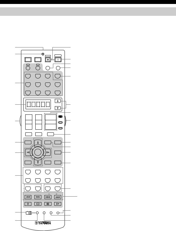
Remote control
This section describes the function of each control on the remote control used to control this unit. Set AMP/ SOURCE/TV to AMP to operate this unit. To operate other components, see “REMOTE CONTROL FEATURES” on page 96.
1 |
|
|
|
|
B |
2 |
POWER |
POWER |
STANDBY |
POWER |
|
|
|
||||
|
TV |
AV |
|
|
C |
|
A |
B |
AUDIO SEL |
SLEEP |
D |
|
|
|
|
|
E |
|
PHONO |
TUNER |
CD |
MULTI CH IN |
F |
|
|
|
|
|
|
3 |
V-AUX |
CBL/SAT |
MD/TAPE |
CD-R |
|
|
DTV |
VCR 1 |
DVR/VCR2 |
DVD |
|
1 Infrared window
Outputs infrared control signals. Aim this window at the component you want to operate.
2 Transmission indicator
Flashes while the remote control is sending infrared signals.
3 Input selector buttons
Select the input source and change the control area. Set AMP/SOURCE/TV to SOURCE and then press TUNER to select TUNER as the input source.
4 Display window
Shows the name of the selected input source that you can control.
5 Light button
Press to light up the remote control buttons and the display window.
4
5
6
7
8
9
0 A
SELECT
+ |
+ |
|
+ |
AMP |
|
|
|||
|
|
|
|
SOURCE |
TV VOL |
CH |
VOLUME |
||
– |
– |
|
– |
TV |
|
|
|
|
|
TV MUTE |
TV INPUT |
MUTE |
|
|
GUI TOP |
PRESET |
EXIT |
|
PURE DIRECT |
TITLE |
|
MENU |
|
|
BAND |
|
|
|
|
|
|
|
|
NIGHT |
|
ENTER |
|
|
AUDIO |
|
|
A/B/C/D/E |
|
|
|
|
|
|
STRAIGHT |
RETURN |
|
DISPLAY |
|
|
|
|
|
|
EFFECT |
STEREO |
MUSIC |
ENTERTAIN |
MOVIE |
|
1 |
2 |
3 |
|
4 |
THX |
STANDARD |
SELECT |
EXTD SUR. |
|
5 |
6 |
7 |
|
8 |
1 MEMORY 2 |
A |
SPEAKERS B |
||
9 |
0 |
+10 |
|
ENT. |
FREQ/TEXT |
EON |
MODE |
PTY SEEK START |
|
REC
DISC SKIP
OFF ON MACRO LEARN CLEAR RE–NAME
G6 GUI TOP, BAND
HDisplays the top screen in the graphical user interface (GUI) menu on your video monitor when AMP/SOURCE/
ITV is set to AMP.
Switches the reception band between FM and AM when AMP/SOURCE/TV is set to SOURCE and TUNER is
Jselected as the input source.
7 Cursor buttons k / n / l / h, ENTER
KSelects and adjusts the DSP program parameters or GUI
Lmenu items when AMP/SOURCE/TV is set to AMP.
MPress l/ hto select a preset station group (A to E) and k/ nto select a preset station number (1 to 8) when
NAMP/SOURCE/TV is set to SOURCE and TUNER is selected as the input source.
8 Sound field program / numeric buttons
Select sound field programs when AMP/SOURCE/TV is set to AMP.
OUse SELECT to play back 2-channel sources in the multichannel format (see page 41).
SUse EXTD SUR. to switch between 5.1 and 6.1/7.1 channel playback of multi-channel software (see page 40). Use numbers 1 to 8 to select preset stations when AMP/
PSOURCE/TV is set to SOURCE and TUNER is selected
Qas the input source.
R9 MEMORY 1/2
Use to recall favorite sound field programs, YPAO settings or additional preset stations (see page 92).
0 MACRO ON/OFF
Turns on or off the macro function (see page 104).
A MACRO
Programs a series of operations to be controlled with a single button (see page 103).
8
B STANDBY
Sets this unit, Zone 2 and Zone 3 to the standby mode (see page 30).
Note
This button is operational only when MASTER ON/OFF on the front panel is pressed inward to the ON position.
C POWER
Turns on this unit, Zone 2 and Zone 3 (see page 30).
Note
This button is operational only when MASTER ON/OFF on the front panel is pressed inward to the ON position.
D AUDIO SEL
Toggles the priority for the type of audio input jack between AUTO, HDMI, COAX/OPT and ANALOG when one component is connected to two or more input jacks on the rear panel (see page 44).
E SLEEP
Sets the sleep timer.
F MULTI CH IN
Selects MULTI CH INPUT when using an external decoder, etc.
G SELECT k / n
Selects another input source that you can control independently of the input source selected with the input selector buttons.
H VOLUME +/–
Increases or decreases the volume level.
I AMP/SOURCE/TV
Selects the component you want to control with the remote control.
AMP
Set to this position to operate this unit.
SOURCE
Set to this position to operate the component selected with an input selector button.
TV
Set to this position to operate the television assigned to either DTV or PHONO.
Note
If televisions are assigned to both DTV and PHONO, the one assigned to DTV takes priority and gets operated when AMP/ SOURCE/TV is set to TV.
y
To set the remote control codes for other components, see page 98.
CONTROLS AND FUNCTIONS
J MUTE
Mutes the sound. Press again to restore the audio output to the previous volume level.
K PURE DIRECT
Turns on or off the PURE DIRECT mode (see page 42).
L EXIT
Exits the GUI mode.
M NIGHT
Turns on or off the night listening modes (see page 42).
N STRAIGHT (EFFECT)
Switches the sound field programs off or on. When STRAIGHT is selected, 2-channel or multi-channel input signals are output directly from their respective speakers without effect processing.
O SPEAKERS A/B
Turns on or off the set of front speakers connected to the SPEAKERS A and/or B terminals on the rear panel each time the corresponding button is pressed.
P RE-NAME
Changes the name of the input source in the display window (see page 102).
Q CLEAR
Clears remote control codes or functions acquired from the learn, macro and rename features (see page 105).
R LEARN
Programs remote control codes or functions from other remote controls (see page 100).
SRadio Data System tuning buttons (U.K. and Europe models only)
These buttons are operational only when TUNER is selected as the input source.
FREQ/TEXT
Switches the Radio Data System display between the PS mode, PTY mode, RT mode, CT mode (if the station offers the corresponding data services) and the frequency display (see page 53).
PTY SEEK MODE
Sets this unit to the PTY SEEK mode (see page 54).
PTY SEEK START
Starts searching for a station after the desired program type has been selected in the PTY SEEK mode
(see page 54).
EON
Selects a radio program type (NEWS, INFO, AFFAIRS, SPORTS) tune in automatically (see page 55).
INTRODUCTION
English
9
CONTROLS AND FUNCTIONS
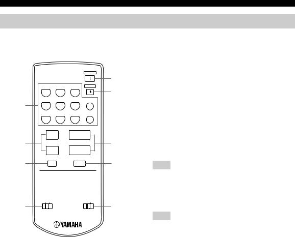
Zone 2/Zone 3 remote control
This section describes the function of each control on the Zone 2/Zone 3 remote control used to control Zone 2 or Zone 3.
|
|
|
|
POWER |
|
|
|
|
|
|
5 |
|
TUNER |
CD |
CD-R |
STANDBY |
|
|
1 |
2 |
3 |
|
6 |
|
DTV |
CBL/SAT MD/TAPE |
PHONO |
|
|
1 |
4 |
5 |
6 |
ENT |
|
|
VCR1 |
DVR/VCR2 |
DVD |
V-AUX |
|
|
7 |
8 |
9 |
0 |
|
|
+ |
+ |
|
|
|
2 |
PRESET |
VOLUME |
7 |
||
|
– |
– |
|
|
|
|
A/B/C/D/E |
|
|
|
|
3 |
|
|
MUTE |
|
8 |
ID1 ID2 |
ZONE 2 ZONE 3 |
4 |
9 |
1 Input selector buttons
Select the desired input source of Zone 2 or Zone 3 and change the control area.
2 PRESET +/–
Selects the preset station number (1 to 8) when TUNER is selected as the input source or Zone 2 or Zone 3.
3 A/B/C/D/E
Selects the preset station group (A to E) when TUNER is selected as the input source or Zone 2 or Zone 3.
4 ID1/ID2 switch
Switches the remote control ID between ID1 and ID2 (see page 99).
5 POWER
Turns on Zone 2 or Zone 3.
Note
This button is operational only when MASTER ON/OFF on the front panel is pressed inward to the ON position.
6 STANDBY
Sets Zone 2 or Zone 3 to the standby mode.
Note
This button is operational only when MASTER ON/OFF on the front panel is pressed inward to the ON position.
7 VOLUME +/–
Increases or decreases the volume level or Zone 2 or Zone 3.
8 MUTE
Mutes the sound of Zone 2 or Zone 3.
Press again to restore the audio output to the previous volume level.
9 ZONE 2/ZONE 3 switch
Switches between the operation mode of Zone 2 and that of Zone 3.
10
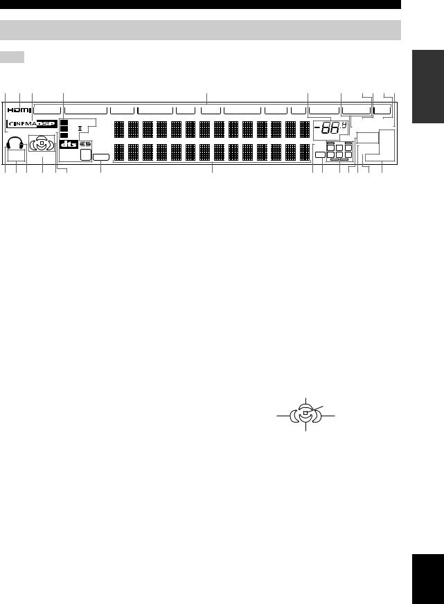
CONTROLS AND FUNCTIONS
Front panel display
Note
The XM indicator is only applicable to the U.S.A. model.
1 2 3 |
4 |
|
|
|
|
|
5 |
|
6 |
7 |
8 9 0 A |
||
|
V-AUX |
DVR/VCR 2 |
VCR 1 |
CBL/SAT |
DTV |
DVD |
MD/TAPE |
CD-R CD |
PHONO TUNER XM |
||||
|
|
DIGITAL |
|
|
|
|
|
|
|
STEREO TUNED |
|||
YPAO HiFi DSP |
PL |
x |
CS |
|
|
|
|
|
|
dB |
AUTO MEMORY |
||
EX |
|
|
|
|
|
|
|
ZONE2 |
PS |
||||
SP |
|
|
|
|
|
|
|
|
|
VOLUME MUTE |
PTY |
||
|
|
|
|
|
|
|
|
|
|
96/24 |
ZONE3 |
RT |
|
A B |
|
|
|
|
|
|
|
|
|
|
NIGHT |
CT |
|
|
DISCRETE 96 |
|
|
|
|
|
|
|
L C R |
||||
SILENT |
VIRTUAL |
PCM |
|
|
|
|
|
|
LFE SL SB SR |
SLEEP |
EON |
||
CINEMA |
MATRIX |
24 |
|
|
|
|
|
|
PTY HOLD |
||||
|
|
|
|
|
|
|
|
||||||
B C D E F G |
|
H |
|
|
|
I |
|
JK LMN O P |
|||||
INTRODUCTION
1 YPAO indicator
Lights up when the AUTO SETUP procedure is in progress and when the AUTO SETUP speaker settings are used without any modifications.
2 HDMI indicator
Lights up when HDMI components are assigned to the HDMI IN 1 and HDMI IN 2 jacks and they are recognized by this unit.
Turns off when no HDMI component is assigned to the either HDMI IN 1 or HDMI IN 2 jack or when no HDMI component is recognized by this unit although they are assigned to the HDMI IN jacks.
See page 112 for details.
3 CINEMA DSP indicator
Lights up when you select a CINEMA DSP sound field program.
4 Decoder indicators
When any of the decoders of this unit operate, the respective indicator lights up.
5 Input source indicators
Light up when the corresponding input source is selected.
6VOLUME level indicator
Indicates the volume level.
7MUTE indicator
Flashes while the MUTE function is on.
8 AUTO indicator
Lights up when this unit is in the automatic tuning mode.
9 STEREO indicator
Lights up when this unit is receiving a stereo signal for an FM stereo broadcast while the AUTO indicator is lit.
0 TUNED indicator
Lights up when this unit is tuned into a station.
A MEMORY indicator
Flashes to indicate that a station can be stored.
B Headphones indicator
Lights up when headphones are connected.
C SILENT CINEMA indicator
Lights up when headphones are connected and a sound field program is selected (see page 39).
D SP A B indicators
Light up according to the set of front speakers selected. Both indicators light up when both sets of front speakers are selected or when bi-wiring.
E VIRTUAL indicator
Lights up when Virtual CINEMA DSP is active (see page 44).
F Sound field indicators
Light up to indicate the active DSP sound fields.
Presence DSP sound field
|
Listening position |
Left surround |
Right surround |
DSP sound field |
DSP sound field |
Surround/surround back DSP sound field
G HiFi DSP indicator
Lights up when you select a HiFi DSP sound field program.
H PCM indicator
Lights up when this unit is reproducing PCM (pulse code modulation) digital audio signals.
I Multi-information display
Shows the name of the current sound field program and other information when adjusting or changing settings.
English
11

CONTROLS AND FUNCTIONS
J 96/24 indicator
Lights up when a DTS 96/24 signal is input to this unit.
K LFE indicator
Lights up when the input signal contains an LFE signal.
LInput channel and speaker indicators
Input channel indicators
Indicate the channel components of the current digital input signal.
L C R
SL SB SR
Presence and surround back speaker indicators
Light up according to the number of presence and surround back speakers set for Presence (see page 85) and Surround Back (see page 84) in Manual Setup when Test Tone in Manual Setup is set to On (see page 83).
y
You can make settings for the presence and surround back speakers automatically by running Auto Setup (see page 32) or manually by adjusting settings for Presence (see page 85) and Surround Back (see page 84) in Manual Setup.
M ZONE 2/ZONE 3 indicators
Light up when Zone 2 or Zone 3 is turned on.
N NIGHT indicator
Lights up when you select a night listening mode.
O SLEEP indicator
Lights up while the sleep timer is on.
PRadio Data System indicators (U.K. and Europe models only)
The name of the Radio Data System data offered by the currently received Radio Data System station lights up.
EON
Lights up when a Radio Data System station that offers the EON data service is being received.
PTY HOLD
Lights up while searching for stations in the PTY SEEK mode.
12
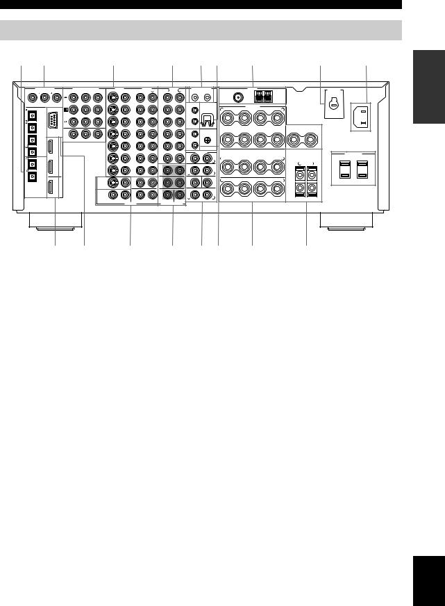
CONTROLS AND FUNCTIONS
Rear panel
1 |
2 |
|
|
|
|
3 |
|
|
|
4 |
|
|
5 6 |
|
|
7 |
|
|
|
8 |
9 |
0 |
|
DIGITAL INPUT |
COMPONENT VIDEO |
VIDEO |
|
AUDIO |
AUDIO |
CONTROL OUT |
|
|
TUNER |
|
|
|
|
VOLTAGE |
|
||||||||
|
|
COAXIAL |
Y |
PB |
PR |
S VIDEO |
VIDEO |
R |
L |
R |
L |
+12V 15mA MAX. |
FM ANT |
|
GND |
|
AM ANT |
|
|
||||
|
|
|
DVD |
|
|
|
|
|
|
(PLAY) |
|
75Ω |
|
|
|
|
|
|
SELECTOR |
|
|||
|
|
|
|
|
|
|
|
|
IN |
|
|
|
|
|
|
|
|
|
|
AC IN |
|||
|
|
|
|
|
|
|
DVD |
|
|
|
1 |
|
2 |
UNBAL. |
|
|
|
|
|
|
|
|
|
|
|
|
|
|
|
|
|
|
|
|
|
|
|
|
|
|
|
|
|
|
|||
CD |
DVD |
DVR/ |
|
|
|
|
|
|
|
MD/TAPE |
|
REMOTE |
WRENCH |
|
|
|
|
|
|
|
|
|
|
|
|
VCR 2 |
DTV |
|
|
|
|
|
|
|
|
|
|
HOLDER |
+ |
– |
SPEAKERS |
– |
+ |
|
|
|
|
CD |
OPTICAL |
|
|
|
|
|
DTV |
|
|
|
|
IN |
|
R |
A |
L |
|
|
|
||||
|
|
|
|
|
|
|
OUT |
|
|
|
|
|
|
|
|
|
|||||||
|
|
|
CBL/ |
|
|
|
|
|
|
(REC) |
|
1 |
|
|
|
|
|
|
|
|
|
|
|
|
|
|
|
|
|
|
|
|
(PLAY) |
|
|
|
|
|
|
|
|
|
|
|
|
||
|
|
|
SAT |
|
|
|
CBL/ |
|
|
IN |
|
OUT |
|
|
|
|
|
|
|
|
|
|
|
DVD |
|
|
|
|
|
|
|
|
|
|
|
|
|
|
|
|
|
|
|
|
|
||
|
|
|
|
|
|
SAT |
|
|
|
|
|
|
|
|
|
|
|
|
|
|
|
|
|
|
|
|
|
|
|
|
|
|
|
CD-R |
|
|
|
FRONT |
|
B |
|
|
CENTER |
|
|
|
|
DTV |
|
|
|
|
|
|
IN |
|
|
|
|
IN |
|
GND |
+ |
– |
– |
+ |
– |
+ |
|
|
|
|
RS-232C |
|
|
|
|
|
|
|
|
|
|
|
|
|
|
|
|
|
|
|
|||
|
|
|
|
|
|
|
|
|
|
OUT |
|
|
|
|
|
|
|
|
|
|
|
|
|
|
|
IN 1 |
|
MONITOR OUT |
|
|
VCR 1 |
|
|
(REC) |
|
2 |
|
|
|
|
|
|
|
|
|
|
|
CBL/SAT |
|
|
|
|
|
|
OUT |
|
|
CD |
|
OUT |
|
|
|
|
|
|
|
|
|
|
|
|
|
|
|
|
|
|
|
|
|
PHONO |
|
|
PRE OUT |
|
|
|
|
|
SPEAKER IMPEDANCE |
|
|
||
|
|
|
|
|
|
|
|
|
|
|
FRONT |
|
|
|
|
|
|
|
AC OUTLETS |
|
|||
|
|
|
|
|
|
|
|
|
|
|
|
|
|
|
|
SURROUND/ZONE 2(3) |
|
|
|
SWITCHED |
|
||
MD/TAPE |
|
IN 2 |
|
|
|
|
IN |
|
|
|
|
|
|
R |
+ |
– |
|
– |
+ |
L |
|
50W MAX.TOTAL |
|
|
|
|
|
|
|
|
|
|
|
|
R |
|
L |
|
|
|
|
|
R |
L |
|
|
|
|
|
|
|
|
|
|
DVR/VCR 2 |
|
|
FRONT(6CH)/SB(8CH) |
|
SURROUND |
|
|
|
|
|
|
|
|
|||
CD-R |
|
|
|
|
|
|
OUT |
|
|
|
|
|
|
|
|
|
|
|
|
|
|
|
|
|
|
|
|
|
|
|
|
|
|
|
|
R |
|
L |
|
|
|
|
|
+ |
|
|
|
|
|
|
|
|
MONITOR |
|
ZONE |
|
|
SURROUND |
|
SUBWOOFER |
CENTER |
+ |
– |
|
– |
+ |
|
|
|
|
|
|
|
|
|
|
|
|
|
|
|
|
|
|
|
|
|
|
|
||||||
|
|
OUT |
|
|
OUT |
|
2 |
|
|
|
|
|
|
R |
|
L |
|
|
|
||||
|
|
|
|
|
|
|
|
|
|
|
|
|
|
|
|
|
|
|
|||||
|
|
|
|
|
|
|
ZONE |
|
|
|
|
|
|
SINGLE |
|
|
|
|
|
– |
|
|
|
DIGITAL |
|
|
|
ZONE 2 |
|
|
|
|
|
|
|
(SB) |
|
|
|
|
|
|
|
|
|
||
|
|
|
VIDEO |
|
3 |
|
|
|
|
|
|
|
|
|
|
|
|
|
|
|
|
||
OUTPUT |
HDMI |
|
|
|
|
|
|
|
|
|
R |
|
L |
|
|
|
SINGLE |
|
|
|
|
|
|
|
|
|
|
|
|
|
|
|
|
|
|
|
|
|
|
|
PRESENCE/ZONE 2(3) |
|
|
||||
|
|
|
|
|
|
|
|
|
|
SUBWOOFER |
CENTER |
SURROUND BACK/PRESENCE |
|
SURROUND BACK |
|
|
|
||||||
|
|
|
|
|
|
|
OUTPUT |
|
|
MULTI CH INPUT |
|
|
|
|
|
|
|
|
|
|
|
|
|
|
|
|
|
|
|
|
|
|
|
|
|
|
|
|
|
|
|
|
|
|
(General model) |
||
|
|
A |
|
B |
|
|
C |
|
|
D |
|
E F |
|
|
G |
|
|
|
H |
|
|
||
INTRODUCTION
1 DIGITAL OUTPUT jacks
See pages 24, 25 and 27 for connection information.
2 DIGITAL INPUT jacks
See pages 24, 25 and 27 for details.
3 Video component jacks
See pages 24 and 25 for connection information.
4 Audio component jacks
See pages 24, 25 and 27 for connection information.
5 CONTROL OUT jacks
These are control expansion terminals for factory use only.
6 WRENCH HOLDER
Use to hook the supplied speaker terminal wrench when not in use (see page 16).
7 Antenna terminals
See page 29 for connection information.
8VOLTAGE SELECTOR
(Asia and General models only)
See page 30 for detailed information.
9 AC OUTLETS
Use to supply power to your other A/V components (see page 30).
0 AC IN
Use this inlet to plug in the supplied power cable (see page 30).
A HDMI IN/OUT connectors
See page 112 for connection information.
B RS-232C terminal
This is a control expansion terminal for factory use only. Consult you dealer for details.
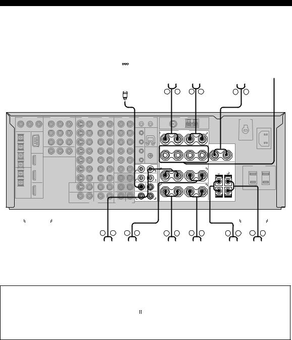
CZONE 2/ZONE 3 OUTPUT jacks
See page 108 for details.
DMULTI CH INPUT jacks
See page 26 for connection information.
E PRE OUT jacks
See page 28 for connection information.
FREMOTE 1/2 IN/OUT jacks
See page 108 for details.
GSpeaker terminals
See page 15 for connection information.
H PRESENCE/ZONE 2(3) speaker terminals
See page 17 for connection information.
English
13
CONNECTIONS
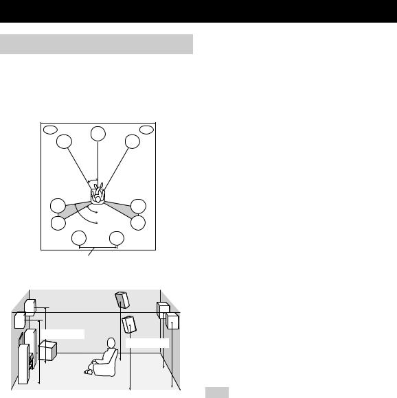
Before connecting speakers
The speaker layout below shows the standard ITU-R* speaker setting. You can use it to enjoy CINEMA DSP, multi-channel audio sources and THX.
*ITU-R is the radio communication sector of the ITU (International Telecommunication Union).
PL |
PR |
|
C |
FL |
FR |
30˚
SL |
|
SR |
|
|
60˚ |
SL |
80˚ |
SR |
|
SBL |
SBR |
More than 30 cm
1.8 m |
1.8 m |
Front speakers (FR and FL)
The front speakers are used for the main source sound plus effect sounds. Place these speakers an equal distance from the ideal listening position. The distance of each speaker from each side of the video monitor should be the same.
Center speaker (C)
The center speaker is for the center channel sounds (dialog, vocals, etc.). If for some reason it is not practical to use a center speaker, you can do without it. Best results, however, are obtained with the full system. Align the front face of the center speaker with the front face of your video monitor. Place the speaker centrally between the front speakers and as close to the monitor as possible, such as directly over or under it.
Surround speakers (SR and SL)
The surround speakers are used for effect and surround sounds. Place these speakers behind your listening position, facing slightly inwards, about 1.8 m above the floor.
Surround back speakers (SBR and SBL)
The surround back speakers supplement the surround speakers and provide for more realistic front-to-back transitions. Place these speakers directly behind the listening position and at the same height as the surround speakers. They should be positioned at least 30 cm apart. Ideally, they should be positioned at the same width as the front speakers.
Subwoofer
The use of a subwoofer, such as the YAMAHA Active Servo Processing Subwoofer System, is effective not only for reinforcing bass frequencies from any or all channels, but also for high fidelity reproduction of the LFE (lowfrequency effect) channel included in Dolby Digital and DTS software. The position of the subwoofer is not so critical, because low bass sounds are not highly directional. But it is better to place the subwoofer near the front speakers. Turn it slightly toward the center of the room to reduce wall reflections.
Presence speakers (PR and PL)
Presence speakers supplement the sound from the front speakers with extra ambient effects produced by CINEMA DSP (see page 58). These effects include sounds that filmmakers intend to locate a little farther back behind the screen in order to create more theater-like ambience. Place these speakers at the front of the room about 0.5 – 1 m outside the front speakers, facing slightly inwards, and about 1.8 m above the floor.
Note
Surround back and presence speakers do not output sound simultaneously. You can set to prioritize either set of speakers using the PR/SB Priority parameter in Manual Setup (see page 79).
14
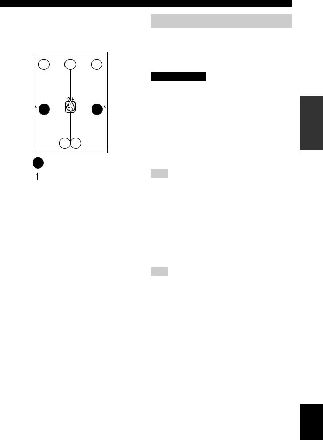
■ Di-pole speaker layout
Either di-pole or direct radiating speaker types can be used for THX surround. If you choose di-pole speakers, please place the surround and surround back speakers according to the speaker layout below.
FL |
C |
FR |
SL |
SR |
SBL SBR
: Di-pole speaker
: Direction of the di-pole speaker phase
CONNECTIONS
Connecting speakers
Be sure to connect the left channel (L), right channel (R), “+” (red) and “–” (black) properly. If the connections are faulty, no sound will be heard from the speakers, and if the polarity of the speaker connections is incorrect, the sound will be unnatural and lack bass.
CAUTION
•If you will use 6 ohm speakers, be sure to set this unit’s speaker impedance setting to 6 ohms before using (see page 31). If you will use 8 ohm speakers, use this unit’s initial setting for speaker impedance.
•Before connecting the speakers, make sure that this unit is disconnected from the power source.
•Do not let the bare speaker wires touch each other or do not let them touch any metal part of this unit. This could damage this unit and/or speakers.
•Use magnetically shielded speakers. If this type of speaker still creates interference with the monitor, place the speakers away from the monitor.
Note
A speaker cord is actually a pair of insulated cables running side by side. One cable is colored or shaped differently, perhaps with a stripe, groove or ridges. Connect the striped (grooved, etc.) cable to the “+” (red) terminals on this unit and your speaker. Connect the plain cable to the “–” (black) terminals.
■ Connecting to the speaker terminals
FRONT terminals
Connect one or two speaker systems to these terminals. If you use only one speaker system, connect it to either of the FRONT A or B terminals.
Note
The Canada model cannot output to two pairs of speaker systems simultaneously.
CENTER terminals
Connect a center speaker to these terminals.
SURROUND ZONE 2(3) terminals
Connect surround speakers to these terminals.
SUBWOOFER jack
Connect a subwoofer with a built-in amplifier, such as the YAMAHA Active Servo Processing Subwoofer System, to this jack.
SURROUND BACK terminals
Connect surround back speakers to these terminals.
If you only connect one surround back speaker, connect it to the left (L) terminals.
PREPARATION
English
15
CONNECTIONS
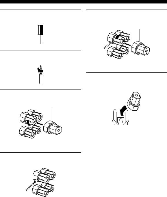
1Remove approximately 10 mm of insulation from each of the speaker cables.
10 mm
2Twist the exposed wires of the cable together to prevent short circuits.
3Loosen the knob using the supplied speaker terminal wrench.
Speaker terminal wrench
Red: positive (+)
Black: negative (–)
4Insert one bare wire into the hole on the side of each terminal.
Red: positive (+)
Black: negative (–)
5Tighten the knob to secure the wire using the supplied speaker terminal wrench.
Speaker terminal wrench
Red: positive (+)
Black: negative (–)
6Hook the speaker terminal wrench onto WRENCH HOLDER on the rear panel of this unit when not in use.
16
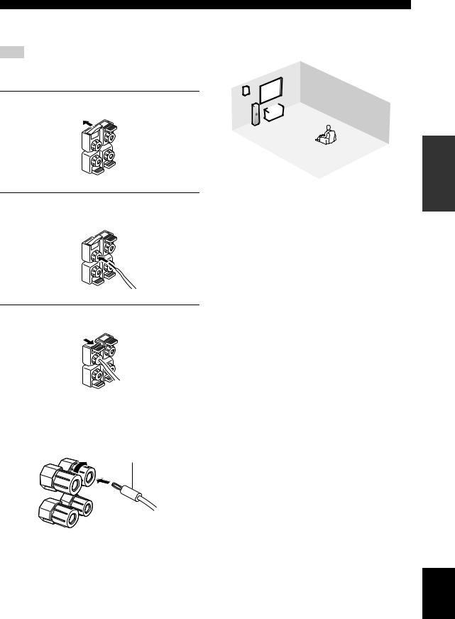
PRESENCE/ZONE 2(3) terminals
Connect presence speakers to these terminals.
Note
You can also use these terminals to connect the Zone 2 speakers (see page 109).
1 Open the tab.
2Insert one bare wire into the hole of each terminal.
3 Return the tab to secure the wire.
CONNECTIONS
■ Speaker layout
Refer to the following illustration as to where to place each speaker in your listening room.
|
9 |
|
|
10 |
2 |
|
|
4 |
|
|
|
|
1 |
7 |
|
|
|
||
3 |
|
|
|
|
|
|
|
|
8 |
|
5 |
|
|
6 |
|
|
|
|
1Subwoofer
2Front right speaker
3Front left speaker
4Center speaker
5Surround back right speaker
6Surround back left speaker
7Surround right speaker
8Surround left speaker
9Presence right speaker
10Presence left speaker
PREPARATION
■ Connecting the banana plug
(With the exception of U.K., Europe and Asia models) First, tighten the knob and then insert the banana plug connector into the end of the corresponding terminal.
Banana plug
(With the exception of U.K., Europe and Asia models)
y
You can also use banana plugs with the PRESENCE/ZONE 2(3) speaker terminals. Open the tab and then insert one banana plug connector into the hole of each terminal. Do not attempt to close the tabs after connecting the banana plugs.
English
17
CONNECTIONS
|
|
|
|
|
|
Front speakers (A) |
|
||||||||||||||||||||
|
|
|
|
|
|
|
Right |
Left |
|
||||||||||||||||||
Subwoofer with |
|
|
|
|
|
|
|
|
|
|
|
|
|
|
|
|
|
|
|
|
|
||||||
|
|
|
|
|
|
|
|
|
|
|
|
|
|
|
|
|
|
|
|
|
|||||||
built-in amplifier |
|
|
|
|
|
|
|
|
|
|
|
|
|
Center |
Front |
||||||||||||
|
|
|
|
|
|
|
|
|
|
|
|
|
|
|
|
|
|
|
|
speaker |
speakers |
||||||
|
|
|
|
|
|
|
|
|
|
|
|
|
|
|
|
|
|
|
|
|
|
|
|
|
|
|
(B) |
|
|
|
|
|
|
|
|
|
|
|
|
|
|
|
|
|
|
|
|
|
|
|
|
|
|
|
|
|
|
|
|
|
|
|
|
|
|
|
|
|
|
|
|
|
|
|
|
|
|
|
|
|
|
|
|
|
|
|
|
|
|
|
|
|
|
|
|
|
|
|
|
|
|
|
|
|
|
|
|
|
|
|
|
|
|
|
|
|
|
|
|
|
|
|
|
|
|
|
|
|
|
|
|
|
|
|
|
|
|
|
|
|
|
|
|
|
|
|
|
|
|
|
|
|
|
|
|
|
|
|
|
|
|
|
|
|
|
|
|
(General model)
PRE OUT
FRONT
R 
 L
L
SURROUND
R 
 L
L
SUBWOOFER CENTER
SINGLE (SB)
R L
SURROUND BACK/PRESENCE
|
+ |
– |
SPEAKERS |
– |
+ |
|
|
R |
A |
L |
|
||||
|
|
|
|
|
|||
FRONT |
|
B |
|
|
CENTER |
|
|
|
+ |
– |
– |
+ |
– |
+ |
|
|
|
|
|
|
|
SPEAKER IMPEDANCE |
|
|
|
SURROUND/ZONE 2(3) |
|
|
|
||
R |
+ |
– |
|
– |
+ |
L |
|
|
|
|
|
|
|
R |
L |
|
|
|
|
|
|
+ |
|
R |
+ |
– |
|
– |
+ |
L |
|
|
|
|
|
|
|
– |
|
|
|
|
|
SINGLE |
|
|
|
|
|
SURROUND BACK |
|
PRESENCE/ZONE 2(3) |
|||
|
|
|
|
|
|
|
|
|
|
|
|
|
|
|
|
|
|
|
|
|
|
|
|
|
|
|
|
|
|
|
|
|
|
|
|
|
|
|
|
|
|
|
|
|
|
|
|
|
|
|
|
|
|
|
|
|
|
|
|
|
|
|
|
|
|
|
|
|
|
|
|
|
|
|
|
|
|
|
|
|
|
|
|
|
|
|
|
|
|
|
|
|
|
|
|
|
|
|
|
|
|
|
|
|
|
|
|
|
|
|
|
|
|
|
|
|
|
|
|
|
|
|
|
|
|
|
|
|
|
|
|
|
|
|
|
|
|
|
|
|
|
|
|
|
|
|
|
|
|
|
|
|
|
|
|
|
|
|
|
|
|
|
|
|
|
|
|
|
|
|
|
|
|
|
|
|
|
|
Right |
|
|
Left |
|
Right |
|
Left |
|
Right |
|
Left |
|||||||||||||||||||
|
|
|
Surround speakers |
Surround back speakers |
Presence speakers |
|||||||||||||||||||||||||||||
•You can connect both surround back and presence speakers to this unit, but they do not output sound simultaneously. You can set to prioritize either set of speakers using the PR/SB Priority parameter in Manual Setup (see page 79).
•The surround back speakers output the surround back channel included in Dolby Digital EX and DTS-ES software and operate
only when the Dolby Digital EX, DTS-ES, Dolby Pro Logic x, THX Select2, THX Music, THX Games or THX Surround EX decoder is turned on.
•The presence speakers output ambient effects created by the DSP sound fields. They do not output sound when other sound fields are selected.
18
Using bi-wire and bi-AMP connections
Some of the speakers commercially available these days have speaker wire connections that allow bi-wiring or biamplification to enhance the performance of the speaker system. This unit allows you to make bi-wire and bi-AMP connections to one speaker system. Check if your speakers support bi-wiring or bi-amplification. As these speakers are shipped to you, you will note gold-plated shorting bars or bridges, one connecting the two red input terminals and the other connecting the two black input terminals. Remove these shorting bars or bridges only if you plan to bi-wire or bi-AMP your speakers.
■ Conventional connection
If you want to connect your speakers as traditional loudspeakers using the conventional connection method, connect your speakers using the regular left and right speaker wire connections and ignore the second set of terminals.
R + |
– |
A |
– |
+ |
L |
FRONT + |
– |
B |
– |
+ |
|
Shorting bars |
|
|
|
Shorting bars |
|
|
|
|
|
||
or bridges |
|
|
|
|
or bridges |
This unit
■ Bi-wire connection
The bi-wire connection separates the woofer from the combined midrange and tweeter section. A bi-wire compatible speaker has four binding post terminals. These two sets of terminals allow the speaker to be split into two independent sections. This split connects the mid and high frequency drivers to one set of terminals and the low frequency driver to the other pair.
Notes
•Remove the shorting bars or bridges to separate the LPF (low pass filter) and HPF (high pass filter) crossovers.
•To use the bi-wire connections, press SPEAKERS A on the front panel so that SP A lights up in the front panel display.
CONNECTIONS
R + |
– |
A |
– |
+ |
L |
FRONT + |
– |
B |
– |
+ |
|
|
|
|
|
|
This unit
■ Bi-AMP connection
The bi-AMP connection uses two amplifiers for both speakers. One amplifier is connected to the woofer section of a loudspeaker while the other is connected to the combined mid and tweeter section. With this arrangement each amplifier operates over a restricted frequency range. This restricted range presents each amplifier with a much simpler job and each amplifier is less likely to influence the sound in some way. The internal crossover of the speaker consists of a LPF (low pass filter) and a HPF (high pass filter). As its name implies, the LPF passes frequencies below a cutoff and rejects frequencies above the cutoff frequency. Likewise, the HPF passes frequencies above its cutoff.
Notes
•Remove the shorting bars or bridges to separate the LPF (low pass filter) and HPF (high pass filter) crossovers.
•To activate the bi-AMP connections, set BI-AMP to ON in ADVANCED SETUP (see page 95).
•To make the bi-AMP connections, use the FRONT and SURROUND BACK terminals as shown below.
R + |
– A – |
+ L |
FRONT
R + |
– |
– |
+ L |
SINGLE
SURROUND BACK
This unit
PREPARATION
English
19

CONNECTIONS
Information on cables and jacks used for connections
CAUTION
Do not connect this unit or other components to the main power until all connections between components are complete.
■ Cable indications
For analog signals |
|
left analog cables |
L |
right analog cables |
R |
For digital signals |
|
optical cables |
O |
|
|
coaxial cables |
C |
|
|
For video signals |
|
video cables |
V |
|
|
S-video cables |
S |
|
|
For HDMI signals |
|
■ Analog jacks
You can input analog signals from audio components by connecting audio pin cables to the analog jacks on this unit. Connect red plugs to the right jacks and white plugs to the left jacks.
■ Digital jacks
This unit has digital jacks for direct transmission of digital signals through either coaxial or fiber optic cables. You can use the digital jacks to input PCM, Dolby Digital and DTS bitstreams. When you connect components to both the COAXIAL and OPTICAL jacks, priority is given to signals input at the COAXIAL jack. All digital input jacks are compatible with 96-kHz sampling digital signals.
Note
This unit handles digital and analog signals independently. Thus audio signals input at the analog jacks are only output at the analog OUT (REC) jacks. Likewise, audio signals input at the digital (OPTICAL or COAXIAL) jacks are only output at the DIGITAL OUTPUT jacks.
20
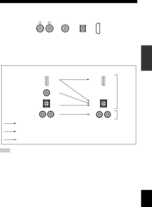
CONNECTIONS
■ Audio jacks
This unit has four types of audio jacks (analog audio, digital audio coaxial, digital audio optical and HDMI). Connection depends on the availability of audio jacks on your other components.
|
AUDIO |
DIGITAL AUDIO |
DIGITAL AUDIO |
HDMI |
||||
R |
L |
(COAXIAL) |
(OPTICAL) |
|
|
|
||
|
|
|
|
|
|
|
|
|
|
|
|
|
|
|
|
|
|
|
|
|
|
|
|
|
|
|
AUDIO jacks |
DIGITAL AUDIO (OPTICAL) jacks |
For conventional analog audio signals. |
For digital audio signals transmitted via digital optical |
DIGITAL AUDIO (COAXIAL) jacks |
cables. |
|
|
For digital audio signals transmitted via digital coaxial |
HDMI jacks |
cables. |
For HDMI digital audio signals. |
■ Audio signal flow for OUT (REC) |
|
Input |
Output |
OUT (REC) |
|
HDMI |
|
DIGITAL AUDIO |
Digital audio |
(COAXIAL) |
|
DIGITAL AUDIO |
|
(OPTICAL) |
|
AUDIO |
Analog audio |
Through
Digital output
Analog output
Notes
•The audio signals input at the HDMI IN 1 or HDMI IN 2 jack are output at the DIGITAL OUTPUT jacks only and are not output at the analog OUT (REC) jacks.
•2-channel as well as multi-channel PCM, Dolby Digital and DTS signals input at the HDMI IN 1 or HDMI IN 2 jack can be output at the HDMI OUT jack only when HDMI Set is set to Other (see page 92).
•2-channel PCM, Dolby Digital and DTS signals except multi-channel PCM signals input at the HDMI IN 1 or HDMI IN 2 jack can be output at the DIGITAL AUDIO (OPTICAL) jacks.
•Copy-protected 2-channel PCM signals with over 48 kHz/16 bit input at the HDMI IN 1 or HDMI IN 2 jack are not output at the DIGITAL AUDIO (OPTICAL) jacks.
PREPARATION
English
21
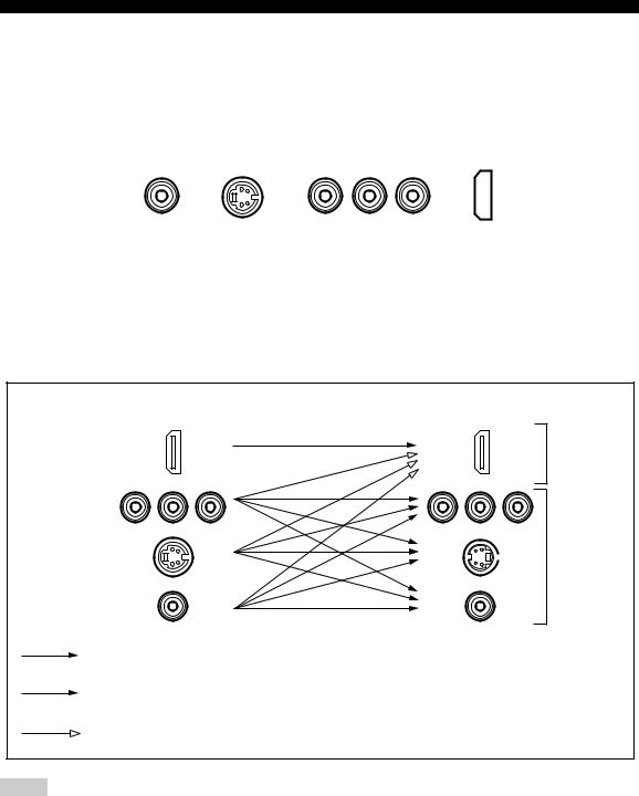
CONNECTIONS
■ Video jacks
This unit has four types of video jacks (composite, component, S-video and HDMI). Connection depends on the availability of input jacks on your monitor. When Conversion is set to On (see page 81), the analog video signals input at the VIDEO, S VIDEO and COMPONENT VIDEO jacks can be output at the VIDEO, S VIDEO and COMPONENT VIDEO jacks interchangeably. In addition, when Conversion is set to On (see page 81) and HDMI Up-Scaling is set to On (see page 81), the analog video signals input at the VIDEO, S VIDEO and COMPONENT VIDEO jacks can be digitally up-converted and output at the HDMI OUT jack.
|
|
COMPONENT VIDEO |
||||
VIDEO |
S VIDEO |
Y |
PB |
HDMI |
||
PR |
||||||
|
|
|
|
|
|
|
VIDEO jacks
For conventional composite video signals.
S VIDEO jacks
For S-video signals, separated into luminance (Y) and color (C) video signals to achieve high-quality color reproduction.
■ Video signal flow for MONITOR OUT
COMPONENT VIDEO jacks
For component signals, separated into luminance (Y) and color difference (PB, PR) to provide the best quality in picture reproduction.
HDMI jacks
For HDMI digital video signals.
HDMI
COMPONENT VIDEO
Input |
Output |
(MONITOR OUT) |
Digital video
S VIDEO |
Analog video |
VIDEO
Through
Component I/P (see page 81) only when Conversion is set to On (see page 81)
HDMI Up-Scaling (see page 81) only when Conversion is set to On (see page 81)
Notes
•The analog video signals output at the COMPONENT VIDEO jacks can be deinterlaced from 480i (NTSC) or 576i (PAL) to 480p (NTSC) or 576p (PAL). Set Component I/P to On in Manual Setup to activate this feature (see page 81).
•The analog video signals input at the COMPONENT VIDEO jacks and output at the S VIDEO or VIDEO jacks cannot be converted to 480p (NTSC) or 576p (PAL) /1080i/720p.
•The analog video signals output at the HDMI jack can be up-scaled to 480p/1080i/720p.
•When the analog video signals are input at the COMPONENT VIDEO, S VIDEO and VIDEO jacks, the priority order of the input signals is as follows where the analog video signals input at the COMPONENT VIDEO jacks have the top priority.
1.COMPONENT VIDEO
2.S VIDEO
3.VIDEO
22
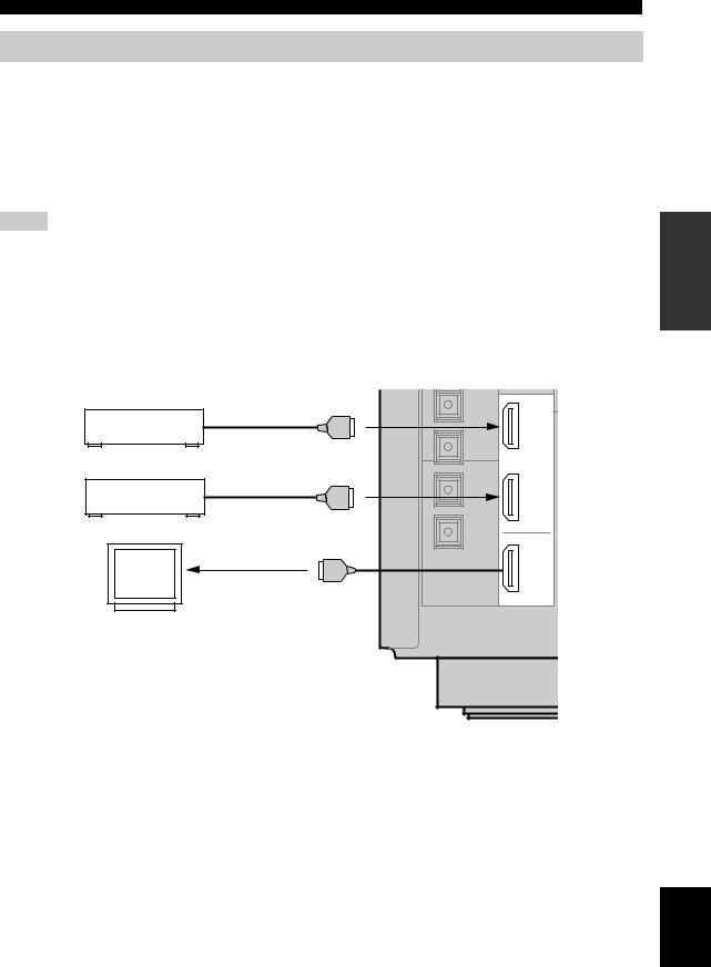
CONNECTIONS
Connecting HDMI components
This unit has the HDMI IN 1 and HDMI IN 2 jacks for digital audio and video signal input as well as the HDMI OUT jack for digital audio and video signal output. Connect the HDMI IN 1 or HDMI IN 2 jack of this unit to the HDMI OUT jack of other HDMI components (such as a DVD player). Connect the HDMI OUT jack of this unit to the HDMI IN jack of other HDMI components (such as a TV and a projector).
The video or audio signals input at the HDMI IN 1 or HDMI IN 2 jack you selected using the HDMI IN menu in I/O Assignment (see page 74) or the INPUT selector on the front panel are output at the HDMI OUT jack of this unit. In addition, the audio signals input at the HDMI IN 1 or HDMI IN 2 jack are output to speakers, headphones and the DIGITAL OUTPUT jacks.
Notes
•We recommend using an HDMI cable shorter than 5 meters with the HDMI logo printed on it.
•Digital audio signals input at the HDMI IN jacks are not output at the analog AUDIO OUT jacks.
•Some audio signals may not be output at the DIGITAL OUTPUT jacks depending on the signal type.
•The analog video signals input at the composite video, S-video and component video jacks can be digitally up-converted and up-scaled to 480p/1080i/720p to be output at the HDMI OUT jack. Set Conversion to On in Manual Setup (see page 81) and adjust settings for HDMI Up-Scaling to activate this feature (see page 81).
•Some video monitors connected to this unit via a DVI connection fail to recognize the HDMI audio signals being input if they are in the standby mode. In this case, the HDMI indicator flashes irregularly and HDCP ERROR appears in the front panel display as if the DVI monitors do not support the HDCP copy protection standards.
|
IN 1 |
DVD Player |
HDMI out |
|
|
|
IN 2 |
Cable TV or |
HDMI out |
Satellite tuner |
|
|
OUT |
Video |
HDMI in |
|
|
monitor |
|
|
HDMI |
PREPARATION
English
23
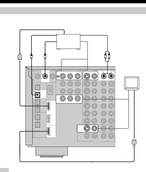
CONNECTIONS
Connecting video components
■ Connecting a DVD player
HDMI out |
|
Optical out |
Audio out |
Coaxial out |
Video out |
|
DVD player |
O |
C |
|
|
|
|
|
R |
L |
DIGITAL INPUT |
COMPONENT VIDEO |
VIDEO |
AUDIO |
|||||
|
COAXIAL |
Y |
PB |
PR |
S VIDEO |
VIDEO |
R |
L |
|
|
DVD |
|
|
|
|
|
|
|
|
|
|
|
|
DVD |
|
|
|
DVD |
|
|
|
|
|
|
Video |
|
|
|
|
|
|
|
|
|
OPTICAL |
|
|
|
|
|
|
monitor |
|
DVD |
|
|
|
|
|
|
|
|
|
|
|
|
|
|
|
|
Video in |
|
IN 1 |
|
MONITOR OUT |
|
|
|
|
|
|
IN 2 |
|
|
|
|
|
|
|
|
|
|
|
MONITOR |
|
|
|
|
|
OUT |
|
|
OUT |
|
|
|
|
DIGITAL |
HDMI |
|
|
|
|
|
|
|
OUTPUT |
|
|
|
|
|
|
|
|
|
|
|
|
|
|
OUTPUT |
|
|
HDMI in
Note
Check the availability of jacks on your DVD player and select one type of connection for audio/video input/output. However, in case you make an HDMI connection, you can make both audio and video connections using a single HDMI cable.
24

CONNECTIONS
■ Connecting other video components
HDMI out |
|
|
|
|
|
|
|
Cable TV or |
|
|
|
|
|
Optical out |
satellite tuner |
|
Audio out |
|
|
|
|
|
|
|
|
||
|
|
Video out |
|
|
|
|
O |
|
|
|
|
|
R L |
|
|
|
|
|
|
|
DIGITAL INPUT |
COMPONENT VIDEO |
VIDEO |
|
AUDIO |
||
COAXIAL |
Y |
PB |
PR |
S VIDEO VIDEO |
R |
L |
DVR/ |
|
Video |
VCR 2 |
DTV |
|
OPTICAL |
|
monitor |
|
CBL/ |
|
|
SAT |
CBL/ |
|
|
|
|
|
SAT |
|
|
IN |
IN 1 |
|
VCR 1 |
CBL/SAT |
|
OUT |
IN 2 |
|
|
OUT |
|
|
HDMI |
|
|
C |
|
R L R L |
|
|
Audio in |
Video out |
DVD recorder |
|
|
or VCR |
Audio out |
Video out |
|
|
Coaxial out |
|
HDMI in |
HDMI out
Note
Check the availability of jacks on your other video components and select one type of connection for audio/video input/output. However, in case you make an HDMI connection, you can make both audio and video connections using a single HDMI cable.
PREPARATION
English
25
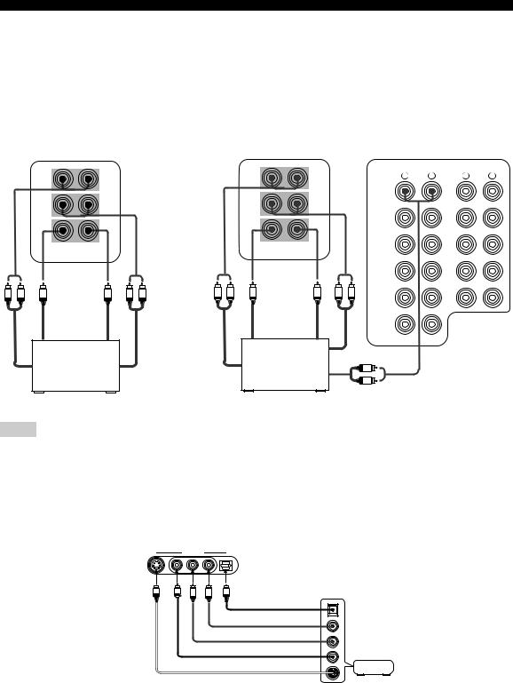
CONNECTIONS
■ Connecting to the MULTI CH INPUT jacks
This unit is equipped with 6 additional input jacks (left and right FRONT, CENTER, left and right SURROUND and SUBWOOFER) for discrete multi-channel input from a multi-format player, external decoder, sound processor or pre-amplifier.
If you set INPUT CH to 8ch in Multi CH Assign (see page 75), you can use the input jacks assigned as FRONT INPUT in Multi CH Assign (see page 75) together with the MULTI CH INPUT jacks to input 8-channel signals.
Connect the output jacks on your multi-format player or external decoder to the MULTI CH INPUT jacks. Be sure to match the left and right outputs to the left and right input jacks for the front and surround channels.
|
For 6-channel input |
|
|
For 8-channel input |
|
|
|
|
|
FRONT(6CH)/SB(8CH) |
|
|
FRONT(6CH)/SB(8CH) |
|
AUDIO |
|
AUDIO |
|
|
|
|
|
R |
L |
R |
L |
|
|
|
|
|
|
|
(PLAY) |
|
|
|
|
|
|
DVD |
|
IN |
|
|
SURROUND |
|
|
SURROUND |
|
|
|
|
|
|
|
|
|
|
|
||
|
|
|
|
|
|
|
MD/TAPE |
|
|
|
|
|
|
DTV |
|
OUT |
|
|
|
|
|
|
|
|
|
|
|
|
|
|
|
|
|
(REC) |
|
|
|
|
|
|
|
|
(PLAY) |
|
|
|
|
|
SUBWOOFER CENTER |
CBL/ |
|
IN |
|
|
SUBWOOFER CENTER |
|
|
|
|
|
||
|
|
|
SAT |
|
|
|
||
|
|
|
|
|
|
|
||
|
MULTI CH INPUT |
|
|
MULTI CH INPUT |
|
|
CD-R |
|
|
|
|
|
|
|
|
||
|
|
|
|
|
|
|
|
|
|
|
|
|
|
IN |
|
OUT |
|
|
|
|
|
|
|
|
|
|
|
|
|
|
|
VCR 1 |
|
(REC) |
|
|
Subwoofer |
|
|
Subwoofer |
|
|
|
|
R L |
R L |
R L |
R L |
|
|
|
||
|
out |
|
|
out |
OUT |
|
CD |
|
|
|
|
|
|
|
|
||
|
Center |
|
|
Center |
IN |
|
|
|
|
out |
|
|
out |
DVR/VCR 2 |
|
|
|
|
|
|
|
|
|
|
|
|
|
Multi-format player/ |
|
|
Multi-format player/ |
Surround out |
|
|
|
Front |
External decoder |
Surround |
Surround |
External decoder |
R |
|
|
|
|
|
L |
|
|
|
|||
out |
|
out |
back out |
|
|
|
|
|
|
|
Front out |
|
|
|
|||
|
|
|
|
|
|
|
|
|
Notes
•When you select MULTI CH INPUT as the input source, this unit automatically turns off the digital sound field processor, and you cannot select sound field programs.
•This unit does not redirect signals input at the MULTI CH INPUT jacks to accommodate for missing speakers. We recommend that you connect at least a 5.1-channel speaker system before using this feature.
•When headphones are used, only front L/R channels are output.
■ Connecting to the VIDEO AUX jacks on the front panel
Use these jacks to connect any video source, such as a game console or video camera, to this unit.
VIDEO AUX
S VIDEO |
VIDEO |
L AUDIO R |
OPTICAL |
S |
V |
L |
R |
O |
Optical out |
|
Audio out R |
|
Audio out L |
Game |
Video out |
console or |
video camera |
|
S-video out |
|
26
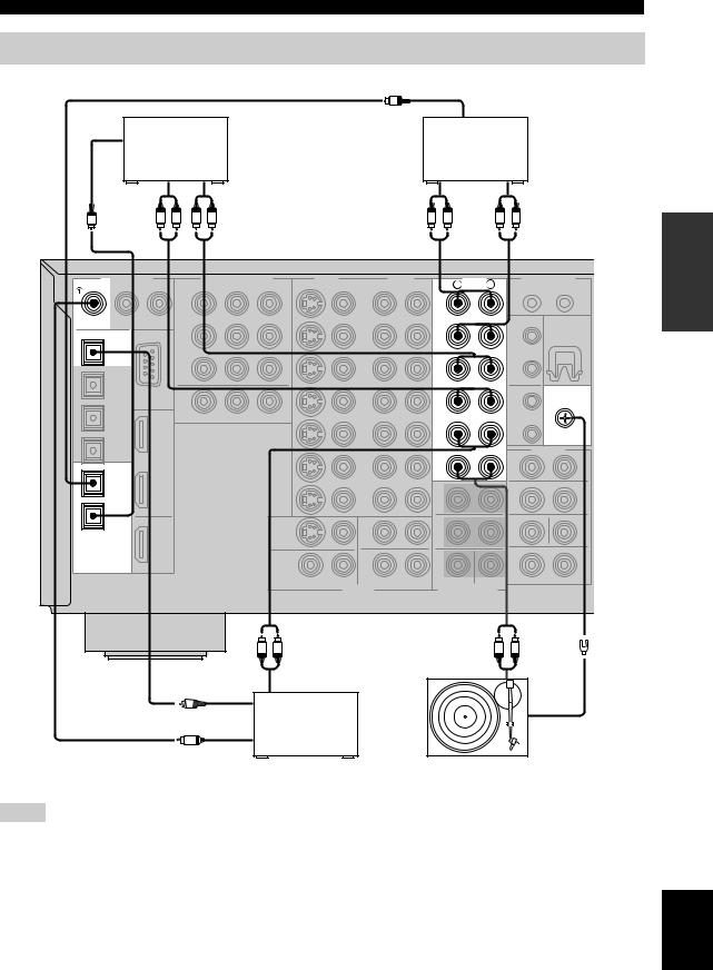
CONNECTIONS
Connecting audio components
|
|
|
O |
|
|
|
|
|
Optical in |
|
|
Optical in |
|
|
MD recorder or |
||
|
CD recorder |
|
|||
|
|
|
tape deck |
||
|
|
|
|
|
|
|
Audio in |
Audio out |
Audio out |
|
Audio in |
O |
R L |
R L |
R |
L |
R L |
|
|
|
|
|
|
DIGITAL INPUT
COAXIAL
CD
 CD OPTICAL
 MD/TAPE
 CD-R
CD-R
DIGITAL
OUTPUT
R |
AUDIO |
L |
|
(PLAY) |
|
IN |
|
MD/TAPE |
|
OUT |
|
(REC) |
|
(PLAY) |
|
IN |
|
CD-R |
|
|
GND |
OUT |
|
(REC) |
|
CD |
|
PHONO |
|
R L R L
|
|
Audio out |
Optical out |
Audio out |
|
|
|
|
O |
|
|
Coaxial out |
CD player |
GND |
C |
|
|
|
|
Turntable |
Notes
•Check the availability of jacks on your audio components and select one type of connection for audio/video input/output.
•PHONO jacks are for connecting a turntable with an MM or high-output MC cartridge. If you have a turntable with a low-output MC cartridge, use an in-line boosting transformer or MC-head amplifier when connecting to these jacks.
•Connect your turntable to the GND terminal to reduce noise in the signal. However you may hear less noise without the connection to the GND terminal for some record players.
PREPARATION
English
27

CONNECTIONS
■ Connecting an external amplifier
If you want to increase the power output to the speakers, or want to use another amplifier, connect an external amplifier to the PRE OUT jacks as follows.
Notes
•When audio pin plugs are connected to the PRE OUT jacks for output to an external amplifier, it is not necessary to use the corresponding SPEAKERS terminals. Set the volume of the external amplifier connected to this unit to the maximum.
•The signal output at the FRONT PRE OUT and CENTER PRE OUT jacks are affected by the TONE CONTROL settings.
•If SPEAKERS A is turned off and SPEAKERS B is set to Zone B (see page 88), signals will only be output at the FRONT PRE OUT jacks.
PRE OUT
FRONT
1
R L
SURROUND
2
R L
SUBWOOFER CENTER
3


 5
5
SINGLE
(SB)
4
R L
SURROUND BACK/PRESENCE
1FRONT PRE OUT jacks
Front channel line output jacks.
2SURROUND PRE OUT jacks
Surround channel line output jacks.
3SUBWOOFER PRE OUT jack
Connect a subwoofer with built-in amplifier, such as the YAMAHA Active Servo Processing Subwoofer System, to this jack.
4SURROUND BACK/PRESENCE PRE OUT jacks
Surround back or presence channel line output jacks. If you only connect one external amplifier for the surround back channel, connect it to the left (L) jack.
5 CENTER PRE OUT jack
Center channel line output jack.
Notes
•Each PRE OUT jack outputs the same channel signal as the corresponding speaker terminals. However, when both surround back and presence speakers are setup in this unit, the signals output at SURROUND BACK/PRESENCE PRE OUT jacks may not correspond to the correct speakers.
•Adjust the volume level of the subwoofer with the control on the subwoofer.
•Some signals may not be output at the SUBWOOFER PRE OUT jack depending on the Speaker Set settings (see page 83).
28
 Loading...