


G B R
RX-496RDS/496 RX-396RDS/396
Natural Sound Stereo Receiver
Récepteur stéréo
Natural Sound Stereoreceiver
Natural Sound Stereoreceiver
Ricevitore stereo a suono naturale
Receptor estéreo de Sonido Natural
Natural Sound Stereo Ontvanger
OWNER’S MANUAL MODE D’EMPLOI BEDIENUNGSANLEITUNG BRUKSANVISNING MANUALE DI ISTRUZIONI
MANUAL DE INSTRUCCIONES GEBRUIKSAANWIJZING
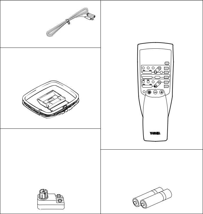
SUPPLIED ACCESSORIES ACCESSOIRES FOURNIS MITGELIEFERTE ZUBEHÖRTEILE MEDFÖLJANDE TILLBEHÖR ACCESSORI IN DOTAZIONE ACCESORIOS INCLUIDOS BIJGELEVERDE ACCESSOIRES
●After unpacking, check that the following parts are included.
●Après le déballage, vérifier que les pièces suivantes sont incluses.
●Nach dem Auspacken überprüfen, ob die folgenden Teile vorhanden sind.
●Kontrollera efter det apparaten packats upp att följande delar finns med.
●Verificare che tutte le parti seguenti siano contenute nell’imballaggio dell’apparecchio.
●Desembalar el aparato y verificar que los siguientes accesorios están en la caja.
●Controleer na het uitpakken of de volgende onderdelen voorhanden zijn.
●Indoor FM Antenna
●Antenne FM intérieure
● UKW-Innenantenne ● FM inomhusantenn ● Antenna FM interna
●Antena FM interior
●FM Binnenantenne
●AM Loop Antenna
●Cadre-antenne AM
●MW-Rahmenantenne
●AM ramantenn
●Antenna AM ad anello
●Antena de cuadro de AM
●AM Lusantenne
●75-ohm/300-ohm antenna adapter (U.K. model only)
●Adaptateur d’antenne 75 ohms/300 ohms (Modèle pour le Royaume-Uni seulement)
●75 Ohm/300 Ohm Antennenstecker (Nur GroßbritannienModell)
●75 ohm/300 ohm antennadapter (Endast modell för Storbritannien)
●Adattatore per antenna da 75 e 300 ohm (Solo modello per la Gran Bretagna)
●Adaptador de antena de 75 ohmios/300 ohmios (Sólo modelo para Reino Unido)
●75 ohm/300 ohm antenne-adapter (Alleen modellen voor Groot-Brittannië)
●Remote Control Transmitter
●Télécommande
●Fernbedienung
●Fjärrkontroll
●Telecomando
●Transmisor de control remoto
●Afstandbediening
YAMAHA HiFi SYSTEM
REMOTE CONTROL TRANSMITTER
|
|
|
AUX |
DIR A DIR B |
REC/PAUSE |
PLAY |
TAPE 2 |
|
|
A/B |
TAPE 1 |
– PRESET |
+ A/B/C/D/E |
TUNER |
|
|
DISC |
PLAY |
CD |
|
|
|
PHONO |
STANDBY/ON |
VOLUME |
|
|
SLEEP |
|
|
|
●Batteries (size AA, R6, UM-3)
●Piles (taille AA, R6, UM-3)
●Batterien (Größe AA, R6, UM-3)
●Batterier (storlek AA, R6, UM-3)
●Batterie (dimensioni AA, R6, UM-3)
●Pilas (tamaño AA, R6, UM-3)
●Batterijen (maat AA, R6, UM-3)
2

Thank you for selecting this YAMAHA Stereo receiver.
FEATURES
● Minimum RMS Output Power per Channel
RX-496RDS and RX-496
75W + 75W (8Ω ) RMS Output
Power, 0.04% THD, 20–20,000 Hz
RX-396RDS and RX-396
50W + 50W (8Ω ) RMS Output
Power, 0.04% THD, 20–20,000 Hz
●High Dynamic Power, Low Impedance Drive Capability
●Continuously Variable LOUDNESS Control
●40-Station Random Access Preset Tuning
●Automatic Preset Tuning
●Preset Station Shifting Capability (Preset Editing)
●IF Count Direct PLL Synthesizer Tuning System
●SLEEP Timer
●Remote Control Capability
●RX-496RDS and RX-396RDS only
Multi-Functions for RDS Broadcast Reception
● RX-496RDS and RX-496 only
PURE DIRECT Switch to Reproduce the Purest Source Sound
English
CONTENTS
SUPPLIED ACCESSORIES ........................... |
2 |
FEATURES ..................................................... |
3 |
CAUTION ........................................................ |
4 |
NOTES ABOUT THE REMOTE CONTROL |
|
TRANSMITTER ............................................... |
5 |
CONNECTIONS .............................................. |
6 |
CONTROLS AND THEIR FUNCTIONS ........ |
10 |
BASIC OPERATIONS ................................... |
14 |
TUNING OPERATIONS ................................ |
17 |
PRESET TUNING ......................................... |
18 |
RECEIVING RDS STATIONS |
|
RX-496RDS and RX-396RDS only ......... |
21 |
TROUBLESHOOTING .................................. |
26 |
SPECIFICATIONS ......................................... |
27 |
3

CAUTION : READ THIS BEFORE OPERATING YOUR UNIT.
1.To assure the finest performance, please read this manual carefully. Keep it in a safe place for future reference.
2.Install this unit in a cool, dry, clean place – away from windows, heat sources, sources of excessive vibration, dust, moisture and cold. Avoid sources of humming (transformers, motors). To prevent fire or electrical shock, do not expose the unit to rain or water.
3.Never open the cabinet. If something drops into the set, contact your dealer.
4.Do not use force on switches, controls or connection wires. When moving the unit, first disconnect the power plug and the wires connected to other equipment. Never pull the wires themselves.
5.The openings on the cabinet assure proper ventilation of the unit. If these openings are obstructed, the temperature inside the cabinet will rise rapidly. Therefore, avoid placing objects against these openings, and install the unit in wellventilated condition. Be sure to allow a space of at least 20 cm behind, 20 cm on the both sides and 30 cm above the top panel of the unit. Otherwise it may not only damage the unit, but also cause fire.
6.Always set the VOLUME control to “–∞ ” before starting the audio source play. Increase the volume gradually to an appropriate level after playback has been started.
7.Do not attempt to clean the unit with chemical solvents; this might damage the finish. Use a clean, dry cloth.
8.Be sure to read the “TROUBLESHOOTING” section regarding common operating errors before concluding that the unit is faulty.
9.When not planning to use this unit for long periods of time (ie., vacation, etc.), disconnect the AC power plug from the wall outlet.
10.To prevent lightning damage, disconnect the AC power plug and antenna cable when there is an electrical storm.
11.Grounding or polarization – Precautions should be taken so that the grounding or polarization of an appliance is not defeated.
12.Do not connect audio equipment to the AC outlet on the rear panel if the equipment requires more power than the outlet is rated to provide.
13.Voltage Selector (General Model only)
The voltage selector on the rear panel of this unit must be set for your local main voltage BEFORE plugging into the AC main supply.
Voltages are 110/120/220/240 V AC, 50/60 Hz.
IMPORTANT
Please record the serial number of this unit in the space below.
Model:
Serial No.:
The serial number is located on the rear of the unit. Retain this Owner’s Manual in a safe place for future reference.
WARNING
TO REDUCE THE RISK OF FIRE OR ELECTRIC SHOCK, DO NOT EXPOSE THIS UNIT TO RAIN OR MOISTURE.
This unit is not disconnected from the AC power source as long as it is connected to the wall outlet, even if this unit itself is turned off. This state is called the standby mode. In this state, this unit is designed to consume a very small quantity of power.
For U.K. customers
If the socket outlets in the home are not suitable for the plug supplied with this appliance, it should be cut off and an appropriate 3 pin plug fitted. For details, refer to the instructions described below.
Note: The plug severed from the mains lead must be destroyed, as a plug with bared flexible cord is hazardous if engaged in a live socket outlet.
Special Instructions for U.K. Model
IMPORTANT
THE WIRES IN MAINS LEAD ARE COLOURED IN ACCORDANCE WITH THE FOLLOWING CODE:
Blue: NEUTRAL
Brown: LIVE
As the colours of the wires in the mains lead of this apparatus may not correspond with the coloured markings identifying the terminals in your plug, proceed as follows: The wire which is coloured BLUE must be connected to the terminal which is marked with the letter N or coloured BLACK. The wire which is coloured BROWN must be connected to the terminal which is marked with the letter L or coloured RED. Making sure that neither core is connected to the earth terminal of the three pin plug.
FREQUENCY STEP switch (General Model only)
Because the interstation frequency spacing differs in different areas, set the FREQUENCY STEP switch (located at the rear) according to the frequency spacing in your area. Before setting this switch, disconnect the AC power plug of this unit from the AC outlet.
4
WARNING
Do not change the IMPEDANCE SELECTOR switch setting while the power to this unit is on, otherwise this unit may be damaged.
IF THIS UNIT FAILS TO TURN ON WHEN THE STANDBY/ON SWITCH IS PRESSED;
The IMPEDANCE SELECTOR switch may not be set to either end. If so, set the switch to either end when this unit is in the standby mode.
IMPEDANCE SELECTOR |
(U.S.A. model) |
|
A OR B:4ΩMIN. /SPEAKER |
A B:8ΩMIN. /SPEAKER |
A OR B:6ΩMIN. /SPEAKER |
A B:I2ΩMIN. /SPEAKER |
IMPEDANCE SELECTOR |
SET BEFORE POWER ON |
A |
English
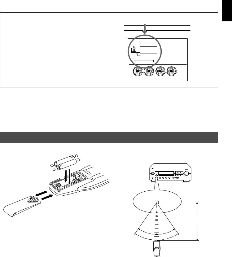
NOTES ABOUT THE REMOTE CONTROL TRANSMITTER
Battery installation |
|
|
|
|
Remote control transmitter operation range |
||||||||||||||||
|
|
|
|
|
|
|
|
|
|
|
|
|
|
|
|
|
|
|
|
|
|
|
|
|
|
|
|
|
|
|
|
|
|
|
|
|
|
|
|
|
|
|
|
|
|
|
|
|
|
|
|
|
|
|
|
|
|
|
|
|
|
|
|
|
|
|
|
|
|
|
|
|
|
|
|
|
|
|
|
|
|
|
|
|
|
|
|
|
|
|
|
|
|
|
|
|
|
|
|
|
|
|
|
|
|
|
|
|
|
|
|
|
|
|
|
|
|
|
|
|
|
|
|
|
|
|
|
|
|
|
|
|
|
|
|
|
|
|
|
|
|
|
|
|
|
|
|
|
|
|
|
|
|
|
|
|
|
|
|
|
|
|
|
|
|
|
|
|
|
|
|
|
|
|
|
|
|
|
|
|
|
|
|
|
|
|
|
|
|
|
|
|
|
|
|
|
|
|
|
|
|
|
|
|
|
|
|
|
|
|
|
|
|
|
|
|
|
|
|
2
1
3
Battery replacement
If you find that the remote control transmitter must be used closer to the main unit, the batteries are weak. Replace both batteries with new ones.
Notes
●Use only AA, R6, UM-3 batteries for replacement.
●Be sure the polarities are correct. (See the illustration inside the battery compartment.)
●Remove the batteries if the remote control transmitter is not used for an extended period of time.
●If batteries leak, dispose of them immediately. Avoid touching the leaked material or letting it come in contact with clothing, etc. Clean the battery compartment thoroughly before installing new batteries.
Remote control sensor
Within approximately 6 m (19.7 feet)
30 |
|
° |
° |
30 |
|
|
|
Notes
●There should be no large obstacles between the remote control transmitter and the main unit.
●If the remote control sensor is directly illuminated by strong lighting (especially an inverter type of fluorescent lamp etc.), it might cause the remote control transmitter not to work correctly. In this case, reposition the main unit to avoid direct lighting.
5

CONNECTIONS
Never plug in this unit and other components until all connections are completed.
CONNECTIONS WITH OTHER COMPONENTS
When making connections between this unit and other components, be sure all connections are made correctly, that is to say L (left) to L, R (right) to R, “+” to “+” and “–” to “–”. Also, refer to the owner’s manual for each component to be connected to this unit.
*If you have YAMAHA components numbered as 1, 3, 4, etc. on the rear panel, connections can be made easily by making sure to connect the output (or input) terminals of each component to the same-numbered terminals of this unit.
Speakers A
Right |
Left |
|
Turntable |
Tape deck, |
|
MD recorder, etc. |
|
|
|
|
OUTPUT |
GND |
LINE OUT LINE IN |
|
|
2 |
|
|
|
|
|
|
|
|
* |
|
|
|
|
|
(U.S.A. model) |
|
|
|
|
|
|
|
|
|
75Ω |
|
|
|
|
|
|
|
|
UNBAL. |
|
|
|
|
|
|
A OR B:4ΩMIN. /SPEAKER |
|
|
|
|
|
|
|
|
A B:8ΩMIN. /SPEAKER |
|
FM |
|
|
|
|
|
|
|
|
ANT |
|
|
|
|
|
|
A OR B:6ΩMIN. /SPEAKER |
1 |
GND |
|
|
REMOTE CONTROL |
|
|
A B:I2ΩMIN. /SPEAKER |
||
|
|
|
IN |
OUT |
|
|
IMPEDANCE SELECTOR |
* |
|
|
|
|
|
SET BEFORE POWER ON |
|||
|
|
|
|
|
|
|
||
GND |
|
|
|
|
|
|
|
|
AM |
|
|
|
|
|
|
|
|
ANT |
|
|
|
|
|
|
|
A |
PHONO |
CD |
AUX |
TAPE 1 |
TAPE 2 |
|
|
|
|
|
|
PLAY /MD REC |
PLAY |
REC |
|
|
|
|
|
|
|
|
|
|
|
|
B |
|
|
|
|
|
|
|
CAUTION SEE INSTRUCTION MANUAL FOR CORRECT SETTING. |
I20V 60Hz |
|
1 |
3 |
4 |
3 or 5 4 or |
6 |
I00W MAX. TOTAL |
||
|
|
SWITCHED |
||||||
|
|
|
|
|
|
|
|
|
|
|
AUDIO SIGNAL |
|
|
|
SPEAKERS |
AC OUTLETS |
|
To AC outlet
OUTPUT |
AUDIO OUT |
LINE OUT |
LINE IN |
|
CD player |
Video cassette player, |
Tape deck, |
||
LD player, etc. |
MD recorder, etc. |
|||
|
||||
*1, *2 : See page 7.
Right |
Left |
Speakers B
6
1
AC* OUTLETS (SWITCHED)
(U.S.A., Canada, Europe and General models)
......................................................... |
2 SWITCHED OUTLETS |
(U.K. and Australia models) ................ |
1 SWITCHED OUTLET |
Use these to connect the power cords from your components to this unit.
The power to the SWITCHED outlets is controlled by this unit’s STANDBY/ON switch or the provided remote control transmitter’s STANDBY/ON key. These outlets will supply power to any component whenever this unit is turned on.
The maximum power (total power consumption of components) that can be connected to the SWITCHED AC OUTLETS is 100 watts.
2
GND* terminal (For turntable use)
Connecting the ground wire of the turntable to the GND terminal will normally minimize hum, but in some cases better results may be obtained with the ground wire disconnected.
English
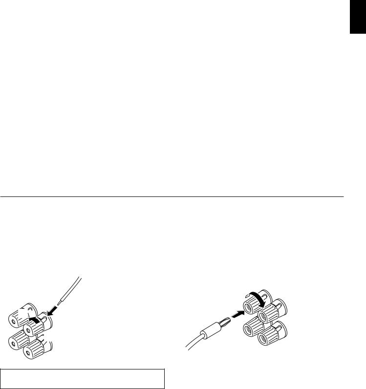
CONNECTING SPEAKERS
Connect the SPEAKERS terminals to your speakers with wire of the proper gauge (cut as short as possible). If the connections are faulty, no sound will be heard from the speakers. Make sure that the polarity of the speaker wires is correct, that is the + and – markings are observed. If these wires are reversed, the sound will be unnatural and lack bass.
Caution
Do not let the bare speaker wires touch each other or any metal part of this unit. This could damage this unit and/or speakers.
How to Connect:
Red: positive (+) Black: negative (–)
2
1

 3
3
Unscrew the knob.
Insert the bare wire. [Remove approx. 5mm (1/4”) insulation from the speaker wires.]
Tighten the knob and secure the wire.
Use speakers with the specified impedance shown on the rear of this unit.
Note
One or two speaker systems can be connected to this unit. If you use only one speaker system, connect it to either the SPEAKERS A or B terminals.
<U.S.A., Canada, Australia and General models only>
Banana Plug connections are also possible. Simply insert the Banana Plug connector into the corresponding terminal.
7
IMPEDANCE SELECTOR switch
Be sure to switch the position only when the power to this unit is not on.
Select the position whose requirements your speaker system meets.
WARNING
Do not change the IMPEDANCE SELECTOR switch setting while the power to this unit is on, otherwise this unit may be damaged.
IF THIS UNIT FAILS TO TURN ON WHEN THE STANDBY/ON SWITCH IS PRESSED;
The IMPEDANCE SELECTOR switch may not be set to either end. If so, set the switch to either end when this unit is in the standby mode.
IMPEDANCE SELECTOR |
(U.S.A. model) |
|
A OR B:4ΩMIN. /SPEAKER |
A B:8ΩMIN. /SPEAKER |
A OR B:6ΩMIN. /SPEAKER |
A B:I2ΩMIN. /SPEAKER |
IMPEDANCE SELECTOR |
SET BEFORE POWER ON |
A |
(Left position)
If you use one pair of speakers, the impedance of each speaker must be 4Ω or higher.
If you use two pairs of speakers, the impedance of each speaker must be 8Ω or higher.
(Right position)
<For U.S.A. model only>
If you use one pair of speakers, the impedance of each speaker must be 6Ω or higher.
If you use two pairs of speakers, the impedance of each speaker must be 12Ω or higher.
<For Canada model only>
The impedance of each speaker must be 6Ω or higher.
<Except U.S.A. and Canada models>
If you use one pair of speakers, the impedance of each speaker must be 8Ω or higher.
If you use two pairs of speakers, the impedance of each speaker must be 16Ω or higher.
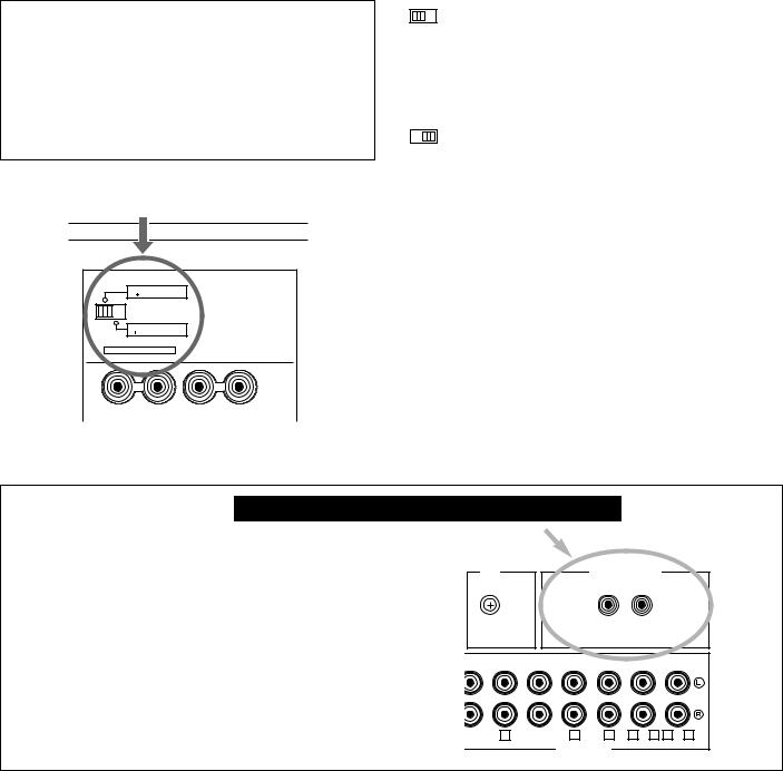
For Custom Installer For U.S.A., Canada and Australia models only
REMOTE CONTROL (IN, OUT) terminals
These terminals are used for custom installation system. When this unit is connected to the components for custom installation system, you can operate this unit with the system remote control.
Connect the REMOTE CONTROL IN terminal of this unit to the output terminal of the central controller for custom installation system.
By connecting the REMOTE CONTROL OUT terminal of this unit to the REMOTE CONTROL IN terminal of the other component, you can also operate the component with the system remote control. In this way, up to 6 components can be connected in series.
GND |
|
|
REMOTE CONTROL |
|
|
|
|
|
IN |
OUT |
|
PHONO |
CD |
AUX |
TAPE 1 |
TAPE 2 |
|
|
|
|
PLAY /MD REC |
PLAY |
REC |
1 |
3 |
4 3 or 5 4 or 6 |
AUDIO SIGNAL
8
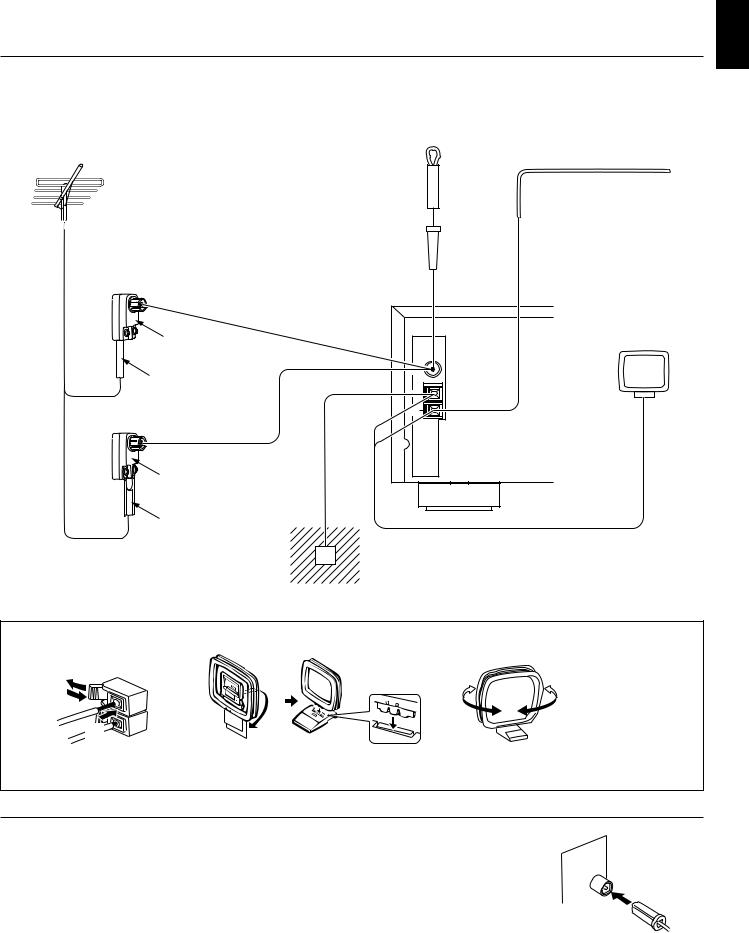
ANTENNA CONNECTIONS
●Each antenna should be connected to the designated terminal(s) correctly, referring to the following diagram.
●Both AM and FM indoor antennas are supplied to this unit. In general, these antennas will provide sufficient signal strength. Nevertheless, a properly installed outdoor antenna will give clearer reception than an indoor one. If you experience poor reception quality, an outdoor antenna may result in improvement.
Outdoor FM antenna |
Outdoor AM antenna |
||
|
|
|
|
Indoor FM antenna (included)
English
75-ohm/300-ohm antenna adapter
75-ohm coaxial cable
75-ohm/300-ohm antenna adapter
75Ω |
UNBAL. |
FM |
ANT |
GND |
AM |
ANT |
AM loop antenna (included)
300-ohm feeder
Ground
Connecting the AM loop antenna
1 |
2 |
3 |
Orient so that the best reception is obtained.
*The AM loop antenna should be placed apart from the main unit. The antenna may be hung on a wall.
*The AM loop antenna should be kept connected, even if an outdoor AM antenna is connected to this unit.
GND terminal
For maximum safety and minimum interference, connect the GND terminal to a good earth ground, which is a metal stake driven into moist earth.
Notes
●When connecting the indoor FM antenna, insert its connector into the FM ANT
terminal firmly. ● If you need an outdoor
FM antenna to improve FM reception quality, either
300-ohm feeder or coaxial cable may be used. In locations troubled by electrical interference, a coaxial cable is preferable.
9
 Loading...