


FOREWORD
This Supplementary Service Manual has been prepared to introduce new service and data for the FZS600 2000. For complete service information procedures it is necessary to use this Supplementary Service Manual together with the following manual.
FZS600 SERVICE MANUAL: 5DM1-AE1
FZS600 2000
SUPPLEMENTARY
SERVICE MANUAL1999 by Yamaha Motor Co., Ltd.
First Edition, June 1999
Any reproduction or unauthorized use without the written permission of Yamaha Motor Co., Ltd. is expressly prohibited.
EB001000
NOTICE
This manual was produced by the Yamaha Motor Company primarily for use by Yamaha dealers and their qualified mechanics. It is not possible to include all the knowledge of a mechanic in one manual, so it is assumed that anyone who uses this book to perform maintenance and repairs on Yamaha scooter has a basic understanding of the mechanical ideas and the procedures of scooter repair. Repairs attempted by anyone without this knowledge are likely to render the scooter unfit for use.
Yamaha Motor Company, Ltd. is continually striving to improve all its models. Modifications and significant changes in specifications or procedures will be forwarded to all authorized Yamaha dealers and will appear in future editions of this manual where applicable.
NOTE:
Designs and specifications are subject to change without notice.
IMPORTANT INFORMATION
Particularly important information is distinguished in this manual by the following.
|
|
The Safety Alert Symbol means ATTENTION! BECOME ALERT! YOUR |
|||
|
|
SAFETY IS INVOLVED! |
|||
WARNING |
Failure to follow WARNING instructions could result in severe injury or death to |
||||
|
|
|
|||
the motorcycle operator, a bystander or a person inspecting or repairing the |
|||||
|
|
||||
|
|
motorcycle. |
|||
|
|
A CAUTION indicates special precautions that must be taken to avoid damage |
|||
CAUTION: |
|
||||
|
|
to the motorcycle. |
|||
NOTE: |
|||||
A NOTE provides key information to make procedures easier or clearer. |
|||||

YP002000
HOW TO USE THIS MANUAL
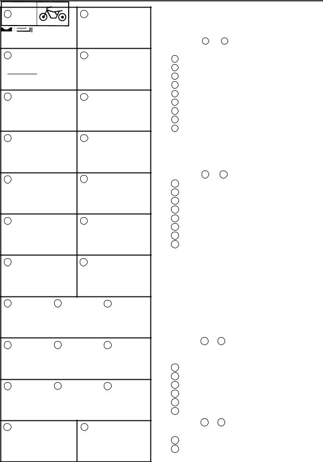
This manual is intended as a handy, easy-to-read reference book for the mechanic. Comprehensive explanations of all installation, removal,disassembly, assembly, repair and inspection procedures are laid out with the individual steps in sequential order.
1The manual is divided into chapters. An abbreviation and symbol in the upper right corner of each page indicate the current chapter. Refer to ªSYMBOLSº on the following page.
2Each chapter is divided into sections. The current section title is shown at the top of each page, except in Chapter 3 (ªPeriodic Inspections and Adjustmentsº), where the sub-section title (-s) appear.
(In Chapter 3, ªPeriodic Inspections and Adjustmentsº, the sub-section title appears at the top of each page, instead of the section title.)
3Sub-section titles appear in smaller print than the section title.
4To help identify parts and clarify procedure steps, there are exploded diagrams at the start of each removal and disassembly section.
5Numbers are given in the order of the jobs in the exploded diagram. A circled number indicates a disassembly step.
6Symbols indicate parts to be lubricated or replaced (see ªSYMBOLSº).
7A job instruction chart accompanies the exploded diagram, providing the order of jobs, names of parts, notes in jobs, etc.
8Jobs requiring more information (such as special tools and technical data) are described sequentially.
2 |
1 |
4 |
3 |
5 |
8 |

 6
6
7 
1 |
2 |
GEN |
SPEC |
|
INFO |
||
|
||
3 |
4 |
|
CHK |
ENG |
|
ADJ |
||
|
||
5 |
6 |
|
COOL |
CARB |
|
7 |
8 |
|
CHAS |
ELEC |
|
9 |
10 |
|
TRBL |
|
|
SHTG |
|
|
11 |
12 |
13 |
14 |
15 |
16 |
17 |
18 |
19 |
20 |
21 |
22 |
23 |
24 |
25 |
EB003000
SYMBOLS
The following symbols are not relevant to every vehicle.
Symbols 1 to 9 indicate the subject of each chapter.
1General information
2Specifications
3Periodic inspection and adjustment
4Engine
5Cooling system
6Carburetor(-s)
7Chassis
8Electrical system
9Troubleshooting
Symbols 10 to 17 indicate the following.
10Serviceable with engine mounted
11Filling fluid
12Lubricant
13Special tool
14Tightening torque
15Wear limit, clearance
16Engine speed
17Electrical data
Symbols 18 to 23 in the exploded diagrams indicate the types of lubricants and lubrication points.
18Apply engine oil
19Apply gear oil
20Apply molybdenum disulfide oil
21Apply wheel bearing grease
22Apply lightweight lithium-soap base grease
23Apply molybdenum disulfide grease
Symbols 24 to 25 in the exploded diagrams indicate the following:
24Apply locking agent (LOCTITE )
25Use new one
CONTENTS
GENERAL INFORMATION
FEATURES . . . . . . . . . . . . . . . . . . . . . . . . . . . . . . . . . . . . . . . . . . . . . . . . . . . 1 SPEEDOMETER . . . . . . . . . . . . . . . . . . . . . . . . . . . . . . . . . . . . . . . . . . . 1
SPECIFICATIONS
GENERAL SPECIFICATIONS . . . . . . . . . . . . . . . . . . . . . . . . . . . . . . . . . . . 2 MAINTENANCE SPECIFICATIONS . . . . . . . . . . . . . . . . . . . . . . . . . . . . . . 3 ENGINE . . . . . . . . . . . . . . . . . . . . . . . . . . . . . . . . . . . . . . . . . . . . . . . . . . . 3 CHASSIS . . . . . . . . . . . . . . . . . . . . . . . . . . . . . . . . . . . . . . . . . . . . . . . . . . 4 CABLE ROUTING . . . . . . . . . . . . . . . . . . . . . . . . . . . . . . . . . . . . . . . . . . . . . 7
PERIODIC INSPECTIONS AND ADJUSTMENTS
PERIODIC MAINTENANCE/LUBRICATION INTERVALS . . . . . . . . . . . 19
CHASSIS . . . . . . . . . . . . . . . . . . . . . . . . . . . . . . . . . . . . . . . . . . . . . . . . . . . . . 21 ADJUSTING THE FRONT FORK LEGS . . . . . . . . . . . . . . . . . . . . . . . 21
CHASSIS
FRONT FORK . . . . . . . . . . . . . . . . . . . . . . . . . . . . . . . . . . . . . . . . . . . . . . . . . 22 CHECKING THE FRONT FORK LEGS . . . . . . . . . . . . . . . . . . . . . . . . 23 ASSEMBLING THE FRONT FORK LEGS . . . . . . . . . . . . . . . . . . . . . . 23
ELECTRICAL
SIGNAL SYSTEM . . . . . . . . . . . . . . . . . . . . . . . . . . . . . . . . . . . . . . . . . . . . . . 26 CIRCUIT DIAGRAM . . . . . . . . . . . . . . . . . . . . . . . . . . . . . . . . . . . . . . . . . 26 SIGNAL SYSTEM CHECK . . . . . . . . . . . . . . . . . . . . . . . . . . . . . . . . . . . 28 CLOCK . . . . . . . . . . . . . . . . . . . . . . . . . . . . . . . . . . . . . . . . . . . . . . . . . . . . . . . 31
FZS600 2000 WIRING DIAGRAM
GEN
FEATURES INFO
GENERAL INFORMATION
FEATURES
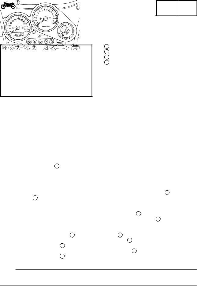
SPEEDOMETER
1 Speedometer
2 Odometer/Tripmeter/Clock
3 ªSELECTº button
4 ªRESETº button
This speedometer is equipped with:
an odometer
two tripmeters
a clock
Odometer and tripmeter modes
When set to ªODOº, the motorcycle's total mileage is indicated.
When set to ªTRIP 1º or ªTRIP 2º, the motorcycle's mileage since the tripmeter was last reset is indicated. Use the tripmeters to estimate how far you can ride on a tank of fuel. This information will enable you to plan fuel stops in the future.
Selecting a mode
Push the ªSELECTº button3 to change between the odometer mode ªODOº, the tripmeter modes ªTRIP 1º and ªTRIP 2º, and the clock mode in the following order:
ªODOº ªTRIP 1º ªTRIP 2º Clock ªODOº
Resetting a meter
To reset either tripmeter 1 or 2 to 0.0, select either by pushing the ªSELECTº button3 and push the ªRESETº button4 for at least one second.
Clock mode
To change the display to the clock mode, push the ªSELECTº button3 .
To change the display back to the odometer mode, push the ªSELECTº button3 .
To set the clock
1.Push both the ªSELECTº button3 and ªRESETº button4 for at least two seconds.
2.When the hour digits start flashing, push the ªRESETº button4 to set the hours.
3.Push the ªSELECTº button3 to change the minutes.
4.When the minute digits start flashing, push the ªRESETº button4 to set the minutes.
5.Push the ªSELECTº button3 to start the clock.
NOTE:
After setting the clock, be sure to push the ªSELECTº button before turning the main switch to ªOFFº, otherwise the clock will not be set.
±1±

|
GENERAL SPECIFICATIONS |
|
SPEC |
|
|||
SPECIFICATIONS |
|
|
|
||||
|
|
|
|||||
GENERAL SPECIFICATIONS |
|
|
|
|
|
|
|
|
|
|
|
|
|
|
|
Model |
|
|
|
FZS600 |
|
|
|
|
|
|
|
|
|
||
Model code: |
|
5DM7 |
|
|
|
||
|
|
5DM8 |
|
|
|
||
|
|
5DM9 |
|
|
|
||
|
|
|
|
|
|
|
|
Fuel: |
|
|
|
|
|
|
|
Type |
|
Regular unleaded gasoline |
|
|
|
||
Fuel tank capacity |
|
20 |
L |
|
|
|
|
Fuel reserve amount |
|
3.5 L |
|
|
|
|
|
|
|
|
|
|
|
|
|
Tire pressure: |
|
|
|
|
|
|
|
Maximum load-except motorcycle |
|
187 kg |
|
|
|
||
Loading condition A* |
|
0 90 kg |
|
|
|
||
front |
|
225 kPa (2.25 kg/cm2, 2.25 bar) |
|||||
rear |
|
250 kPa (2.5 kg/cm2, 2.5 bar) |
|||||
Loading condition B* |
|
90 |
187 kg |
|
|
|
|
front |
|
225 kPa (2.25 kg/cm2, 2.25 bar) |
|||||
rear |
|
290 kPa (2.9 kg/cm2, 2.9 bar) |
|||||
High-speed riding |
|
225 kPa (2.25 kg/cm2, 2.25 bar) |
|||||
front |
|
||||||
rear |
|
290 kPa (2.9 kg/cm2, 2.9 bar) |
|||||
Bulb voltage, wattage quantity: |
|
|
|
|
|
|
|
Headlight |
|
12 V |
60 W/55 W 1 |
|
|
|
|
Marker light |
|
12 |
V |
5 W 1 |
|
|
|
Brake/tail light |
|
12 |
V |
21 W/5 W 2 |
|
|
|
Front turn signal light |
|
12 |
V |
21 W 2 |
|
|
|
Rear turn signal light |
|
12 |
V |
21 W 2 |
|
|
|
Meter light |
|
12 |
V |
2 W 3 |
|
|
|
Indicator light |
|
|
|
|
|
|
|
Neutral indicator light |
|
14 |
V |
1.4 W 1 |
|
|
|
High beam indicator light |
|
14 |
V |
1.4 W 1 |
|
|
|
Oil level warning light |
|
14 |
V |
1.4 W 1 |
|
|
|
Turn indicator light |
|
14 |
V |
1.4 W 2 |
|
|
|
Fuel level warning light |
|
12 |
V |
2 W 1 |
|
|
|
Engine temperature warning light |
|
LED |
|
|
|
|
|
*Load is the total weight of cargo, rider, passenger and accessories.
±2±
|
|
MAINTENANCE SPECIFICATIONS |
|
SPEC |
|
||
MAINTENANCE SPECIFICATIONS |
|
|
|
|
|||
|
|
|
|
||||
ENGINE |
|
|
|
|
|
|
|
|
|
|
|
|
|
|
|
Item |
|
|
Standard |
|
|
Limit |
|
|
|
|
|
|
|
|
|
Valve spring: |
|
|
|
|
|
|
|
Free length |
|
IN/EX |
40.09 mm |
|
|
37.5 mm |
|
Set length (valve closed) |
IN/EX |
34.5 mm |
|
|
|
||
Compressed pressure |
IN/EX |
131.4 X 153.0 N (13.4 X 15.6 kg) |
|
|
|
||
Tilt limit |
|
IN/EX |
|
|
|
2.5_/1.8 mm |
|
Direction of winding |
|
IN/EX |
Clockwise |
|
|
|
|
|
|
|
|
|
|
|
|
Carburetor: |
|
|
|
|
|
|
|
I.D. mark |
|
|
5DM1 01 (GB) (N) (SF) (DK) (D) (NL) |
|
|
|
|
|
|
|
(B) (F) (E) (P) (IRL) (GR) |
|
|
|
|
|
|
|
5DM2 11 (D) (F) |
|
|
|
|
Main jet |
(M.J) |
|
#115 |
|
|
|
|
Main air jet |
(M.A.J) |
#80 |
|
|
|
||
Jet needle |
(J.N) |
|
5D86-3/5 (GB) (N) (SF) (DK) (D) (NL) |
|
|
|
|
|
|
|
(B) (F) (E) (P) (IRL) (GR) |
|
|
|
|
|
|
|
5D92-3/5 (D) (F) |
|
|
|
|
Needle jet |
(N.J) |
|
P-0 |
|
|
|
|
Pilot air jet |
(P.A.J.1) |
#130 |
|
|
|
||
Pilot outlet |
(P.O) |
|
0.95 |
|
|
|
|
Pilot jet |
(P.J) |
|
#12.5 |
|
|
|
|
Bypass 1 |
(B.P.1) |
0.9 |
|
|
|
||
Bypass 2 |
(B.P.2) |
0.8 |
|
|
|
||
Bypass 3 |
(B.P.3) |
0.8 |
|
|
|
||
Pilot screw |
(P.S) |
|
2 |
|
|
|
|
Valve seat size |
(V.S) |
|
1.0 |
|
|
|
|
Starter jet |
(G.S.1) |
0.6 |
|
|
|
||
Starter jet |
(G.S.2) |
0.8 |
|
|
|
||
Throttle valve size |
(TH.V) |
#110 |
|
|
|
||
Fuel level |
(F.L) (with |
3.5 mm |
|
|
|
||
|
special tool) |
|
|
|
|
|
|
Engine idle speed |
|
|
1,150 X 1,250 r/min |
|
|
|
|
Intake vacuum |
|
|
30.7 X 33.3 kPa (230 X 250 mmHg) |
|
|
|
|
|
|
|
|
|
|
|
|
±3±
|
MAINTENANCE SPECIFICATIONS |
|
|
|
SPEC |
|
||||||
CHASSIS |
|
|
|
|
|
|
|
|
|
|
|
|
|
|
|
|
|
|
|
|
|
|
|
|
|
|
|
|
|
|
|
|
|
|
|
|
|
|
Item |
|
Standard |
|
|
|
|
|
|
Limit |
|||
|
|
|
|
|
|
|
|
|
|
|
|
|
Front suspension: |
|
|
|
|
|
|
|
|
|
|
|
|
Front fork travel |
|
120 mm |
|
|
|
|
|
|
|
|||
Fork spring free length |
316.8 mm |
|
|
|
|
|
|
319 mm |
||||
Fitting length |
|
309.8 mm |
|
|
|
|
|
|
|
|||
Collar length |
|
183 mm |
|
|
|
|
|
|
|
|||
Spring Rate |
(K1) |
7.35 N/mm (0.75 kg/mm) |
|
|
|
|
|
|
|
|||
|
(K2) |
13.72 N/mm (1.4 kg/mm) |
|
|
|
|
|
|
|
|||
Stroke |
(K1) |
0 70 mm |
|
|
|
|
|
|
|
|||
|
(K2) |
70 120 mm |
|
|
|
|
|
|
|
|||
Optional spring |
|
No |
|
|
|
|
|
|
|
|||
Oil capacity |
|
465 cm3 |
|
|
|
|
|
|
|
|||
Oil level |
|
132 mm |
|
|
|
|
|
|
|
|||
Oil grade |
|
Fork oil 10W or equivalent |
|
|
|
|
|
|
|
|||
|
|
|
|
|
|
|
|
|
|
|
|
|
Drive chain: |
|
|
|
|
|
|
|
|
|
|
|
|
Type/manufacturer |
50VA7/DAIDO |
|
|
|
|
|
|
|
||||
No. of links |
|
110 |
|
|
|
|
|
|
|
|
|
|
Chain free play |
|
30 45 mm |
|
|
|
|
|
|
|
|||
TIGHTENING TORQUES |
|
|
|
|
|
|
|
|
|
|
|
|
CHASSIS |
|
|
|
|
|
|
|
|
|
|
|
|
|
|
|
|
|
|
|
|
|
|
|||
|
|
|
|
|
Tightening |
|
|
|
||||
Part to be tightened |
|
Thread size |
|
torque |
|
Remarks |
||||||
|
|
|
|
|
Nm |
|
m kg |
|
|
|||
Holder, clutch lever 1 |
|
M6 1.0 |
|
11 |
|
1.1 |
|
|
|
|||
|
|
|
|
|
|
|
|
|
|
|
|
|
±4±
MAINTENANCE SPECIFICATIONS |
|
SPEC |
|
||
ELECTRICAL |
|
|
|
|
|
|
|
|
|
|
|
|
|
|
|
|
|
Item |
Standard |
|
|
Limit |
|
|
|
|
|
|
|
Ignition system: |
|
|
|
|
|
Ignition timing (B.T.D.C.) |
10_/1,250 r/min |
|
|
|
|
Advanced timing (B.T.D.C.) |
50_/4,500 r/min |
|
|
|
|
Advance type |
Digital type |
|
|
|
|
|
|
|
|
|
|
T.C.I.: |
189 231 Ω Y-L |
|
|
|
|
Pickup coil resistance |
|
|
|
||
T.C.I. unit model/manufacturer |
J4T095/MITSUBISHI |
|
|
|
|
|
|
|
|
|
|
Charging system: |
|
|
|
|
|
Type |
A.C. magneto |
|
|
|
|
Model/manufacturer |
F4T359/MITSUBISHI |
|
|
|
|
Standard output |
14 V 18 A at 5,000 r/min |
|
|
|
|
Stator coil resistance |
0.36 0.44 Ω at 20_C/W-W |
|
|
|
|
Starter motor: |
|
|
|
|
|
Model/manufacturer |
SM-13/MITSUBA |
|
|
|
|
I.D. number |
SM-13 |
|
|
|
|
Output |
0.7 kW |
|
|
|
|
Armature coil resistance |
0.0015 0.0025 Ω at 20_C |
|
|
|
|
Brush overall length |
10 mm |
|
|
4 mm |
|
Brush spring pressure |
7.64 10.00 N (779 1,020 gf) |
|
|
|
|
Commutator dia. |
28 mm |
|
|
27 mm |
|
Mica undercut (depth) |
0.7 mm |
|
|
|
|
Mica undercut (width) |
0.8 mm |
|
|
|
|
|
|
|
|
|
|
Starter relay: |
|
|
|
|
|
Model/manufacturer |
MS5F-631/JIDECO |
|
|
|
|
Amperage rating |
180 A |
|
|
|
|
Coil winding resistance |
4.18 4.62 Ω at 20_C |
|
|
|
|
Horn: |
|
|
|
|
|
Type |
Plane type |
|
|
|
|
Quantity |
1 pcs |
|
|
|
|
Model manufacturer |
YF-12/NIKKO |
|
|
|
|
Maximum amperage |
3.0 A |
|
|
|
|
Performance |
105 113 db/2 m |
|
|
|
|
Coil winding resistance |
1.15 1.25 Ω at 20_C |
|
|
|
|
Flasher/hazard relay: |
|
|
|
|
|
Type |
Full transistor type |
|
|
|
|
Model/manufacturer |
FE246BH/DENSO |
|
|
|
|
Self cancelling device |
No |
|
|
|
|
Hazard flasher device |
Yes |
|
|
|
|
Flasher frequency |
75 95 cyl/min |
|
|
|
|
Wattage |
21 W 2 + 3.4 W |
|
|
|
|
|
|
|
|
|
|
Thermostat switch: |
|
|
|
|
|
Model/manufacture |
4BA/DENSO |
|
|
|
|
|
|
|
|
|
|
±5±
 Loading...