


XW4024-120/240-60 XW4548-120/240-60 XW6048-120/240-60
Installation Guide
XW Power System
XW Power Distribution Panel
XW System Control Panel
XW Solar Charge Controller
XW Automatic Generator Start

XW Power System
Installation Guide
About Xantrex
Xantrex Technology Inc. is a world-leading supplier of advanced power electronics and controls with products from 50 watt mobile units to 2.5 MW utility-scale systems for wind, solar, batteries, fuel cells, micro turbines, and backup
power applications in both grid-connected and stand-alone systems. Xantrex products include inverters, battery chargers, programmable power supplies, and variable speed drives that convert, supply, control, clean, and distribute electrical power.
Trademarks
XW Power System is a trademark of Xantrex International. Xantrex is a registered trademark of Xantrex International.
Other trademarks, registered trademarks, and product names are the property of their respective owners and are used herein for identification purposes only.
Notice of Copyright
XW Power System Installation Guide © May 2007 Xantrex International. All rights reserved.
Exclusion for Documentation
UNLESS SPECIFICALLY AGREED TO IN WRITING, XANTREX TECHNOLOGY INC. (“XANTREX”)
(a)MAKES NO WARRANTY AS TO THE ACCURACY, SUFFICIENCY OR SUITABILITY OF ANY TECHNICAL OR OTHER INFORMATION PROVIDED IN ITS MANUALS OR OTHER DOCUMENTATION.
(b)ASSUMES NO RESPONSIBILITY OR LIABILITY FOR LOSSES, DAMAGES, COSTS OR EXPENSES, WHETHER SPECIAL, DIRECT, INDIRECT, CONSEQUENTIAL OR INCIDENTAL, WHICH MIGHT ARISE OUT OF THE USE OF SUCH INFORMATION. THE USE OF ANY SUCH INFORMATION WILL BE ENTIRELY AT THE USER’S RISK; AND
(c)REMINDS YOU THAT IF THIS MANUAL IS IN ANY LANGUAGE OTHER THAN ENGLISH, ALTHOUGH STEPS HAVE BEEN TAKEN TO MAINTAIN THE ACCURACY OF THE TRANSLATION, THE ACCURACY CANNOT BE GUARANTEED. APPROVED XANTREX CONTENT IS CONTAINED WITH THE ENGLISH LANGUAGE VERSION WHICH IS POSTED AT WWW.XANTREX.COM.
Due to continuous quality improvement and product updates, the illustrations shown in this manual may not exactly match the unit purchased.
Date and Revision
May 2007, Revision A
Part Number
975-0239-01-01
Product Numbers
865-1000 (XW 6048-120/240-60)
865-1005 (XW4548-120/240-60)
865-1010 (XW4024-120/240-60)
Contact Information
Telephone: |
1-800-670-0707 |
(toll free in North America) |
Telephone: |
1-360-925-5097 |
(direct) |
Fax: |
1-800-994-7828 |
(toll free in North America) |
Fax: |
1-360-925-5143 |
(direct) |
Email: |
customerservice@xantrex.com |
|
Web: |
www.xantrex.com |
|

About This Guide
Purpose
The purpose of this Installation Guide is to provide explanations and procedures for installing the XW Power System.
Scope
The Guide provides safety guidelines, detailed planning and procedures for installing the XW Inverter/Charger and related system components (the “XW Power System”). It does not provide details about configuration, operation, maintenance or troubleshooting. See the Operation Guide or Owner’s Manual of each device for this information. This Guide also does not provide details about particular brands of batteries. You need to consult individual battery manufacturers for this information.
Audience
The Guide is intended for anyone who needs to install the XW Power System.
Installers should be certified technicians or electricians.
Organization
This guide is organized into four chapters and three appendices.
Chapter 1, “Introduction” lists and describes the components and basic features of the XW Power System.
Chapter 2, “Inverter/Charger Installation” describes how to mount and install the XW Inverter/Charger, and the XW Power Distribution Panel and XW Conduit Box.
Chapter 3, “Xanbus Network Installation” provides detailed information for planning and installing the components necessary for network communication on a Xanbus system.
Chapter 4, “XW Solar Charge Controller Installation” describes how to mount and connect the XW Charge Controller as part of the XW System.
Chapter 5, “XW System Accessories Installation” describes how to mount and install the XW System Control Panel and the Automatic Generator Start.
Appendix A, “Specifications” provides the electrical and environmental specifications for the XW Series.
Appendix B, “Wiring Diagrams” illustrate the most basic configurations and are for reference only. Specific installations may require additional equipment to meet national or local electric codes. Ensure all safety requirements are strictly followed.
Appendix C, “Alternate System Configurations” provides wiring diagrams for inverter/charger installations that do not require use of the power distribution panel and the XW Conduit Box.
975-0239-01-01 |
iii |

About This Guide
Conventions Used
The following conventions are used in this guide.
WARNING
Warnings identify conditions or practices that could result in personal injury or loss of life.
 CAUTION
Cautions identify conditions or practices that could result in damage to the XW Power System components or other equipment.
Related Information
Additional information about operating the XW Inverter/Charger, see the XW
Inverter/Charger Operation Guide (975-0240-01-01).
For more information about related components, refer to:
•XW Power System Intallation Overview (975-0238-01-01)
•XW System Control Panel Owner’s Guide (975-0298-01-01)
•XW Solar Charge Controller Owner’s Guide (975-0283-01-01)
•XW Automatic Generator Start Owner’s Guide (975-0307-01-01)
These guides are available at www.xantrex.com. Printed copies should be included with the components.
For more information about Xantrex Technology, Inc. as well as its products and services visit www.xantrex.com.
iv |
975-0239-01-01 |

Important Safety Instructions
 WARNING
This chapter contains important safety and operating instructions as required by UL and CSA standards for inverters used in residential applications. Read and keep this
Installation Guide for future reference.
1.Before using the inverter, read all instructions and cautionary markings on the unit, the batteries, and all appropriate sections of this manual.
2.Use of accessories not recommended or sold by Xantrex Technology Inc. may result in a risk of fire, electric shock, or injury to persons.
3.The inverter is designed to be permanently connected to your AC and DC electrical systems. Xantrex recommends that all wiring be done by a certified technician or electrician to ensure adherence to the local and national electrical codes applicable in your jurisdiction.
4.To avoid a risk of fire and electric shock, make sure that existing wiring is in good condition and that wire is not undersized. Do not operate the inverter with damaged or substandard wiring.
5.Do not operate the inverter if it has been damaged in any way. If the unit is damaged, see the Warranty and Product Information section at the end of this manual.
6.This unit does not have any user-serviceable parts. Do not disassemble the inverter except where noted for connecting wiring and cabling. See the Warranty Section in the XW Inverter/Charger Operation Guide and other component manuals for instructions on obtaining service. Attempting to service the unit yourself may result in a risk of electrical shock or fire. Internal capacitors remain charged after all power is disconnected.
7.To reduce the risk of electrical shock, disconnect both AC and DC power from the inverter before attempting any maintenance or cleaning or working on any components connected to the inverter. Turning off controls will not reduce this risk.
8.The inverter must be provided with an equipment-grounding conductor connected to the AC input ground.
9.Do not expose this unit to rain, snow, or liquids of any type. This product is designed for indoor use only. Damp environments will significantly shorten the life of this product and corrosion caused by dampness will not be covered by the product warranty.
10.To reduce the chance of short-circuits, always use insulated tools when installing or working with this equipment.
11.Remove personal metal items such as rings, bracelets, necklaces, and watches when working with batteries.
975-0239-01-01 |
v |

Important Safety Instructions
Limitations on Use
WARNING: Limitations on Use
The XW Power System is not intended for use in connection with life support systems or other medical equipment or devices.
Explosive Gas Precautions
1.Working in the vicinity of lead acid batteries is dangerous. Batteries generate explosive gases during normal operation. Therefore, you must read this guide and follow the instructions exactly before installing or using your inverter/charger.
2.To reduce the risk of battery explosion, follow these instructions and those published by the battery manufacturer and the manufacturer of the equipment in which the battery is installed.
FCC Information to the User
This equipment has been tested and found to comply with the limits for a Class B digital device, pursuant to part 15 of the FCC Rules. These limits are designed to provide reasonable protection against harmful interference in a residential installation. This equipment generates, uses and can radiate radio frequency energy and, if not installed and used in accordance with the instructions, may cause harmful interference to radio communications. However, there is no guarantee that interference will not occur in a particular installation. If this equipment does cause harmful interference to radio or television reception, which can be determined by turning the equipment off and on, the user is encouraged to try to correct the interference by one or more of the following measures:
•Reorient or relocate the receiving antenna.
•Increase the separation between the equipment and the receiver.
•Connect the equipment to a circuit different from that to which the receiver is connected.
•Consult the dealer or an experienced radio/TV technician for help.
vi |
975-0239-01-01 |

Contents
Important Safety Instructions - - - - - - - - - - - - - - - - - - - - - - - - - - - - - - - - - - - - - - - - - - - - - - - - -v
Limitations on Use - - - - - - - - - - - - - - - - - - - - - - - - - - - - - - - - - - - - - - - - - - - - - - - - - - - - - - - - - - - - vi Explosive Gas Precautions - - - - - - - - - - - - - - - - - - - - - - - - - - - - - - - - - - - - - - - - - - - - - - - - - - - - - - vi FCC Information to the User - - - - - - - - - - - - - - - - - - - - - - - - - - - - - - - - - - - - - - - - - - - - - - - - - - - - - vi
1 Introduction
System Overview - - - - - - - - - - - - - - - - - - - - - - - - - - - - - - - - - - - - - - - - - - - - - - - - - - - - - - - - - - - 1–2 System Diagram - - - - - - - - - - - - - - - - - - - - - - - - - - - - - - - - - - - - - - - - - - - - - - - - - - - - - - - - - - 1–2 System Components and Accessories - - - - - - - - - - - - - - - - - - - - - - - - - - - - - - - - - - - - - - - - - - - - - - 1–3 XW Inverter/Charger - - - - - - - - - - - - - - - - - - - - - - - - - - - - - - - - - - - - - - - - - - - - - - - - - - - - - - 1–3 XW Conduit Box - - - - - - - - - - - - - - - - - - - - - - - - - - - - - - - - - - - - - - - - - - - - - - - - - - - - - - - - - 1–3 XW Power Distribution Panel Panel and XW Conduit Box - - - - - - - - - - - - - - - - - - - - - - - - - - - - - 1–4 XW Connection Kit for INV2 - - - - - - - - - - - - - - - - - - - - - - - - - - - - - - - - - - - - - - - - - - - - - - - - 1–5 XW Solar Charge Controller - - - - - - - - - - - - - - - - - - - - - - - - - - - - - - - - - - - - - - - - - - - - - - - - - 1–6 XW System Control Panel - - - - - - - - - - - - - - - - - - - - - - - - - - - - - - - - - - - - - - - - - - - - - - - - - - - 1–6 XW Automatic Generator Start - - - - - - - - - - - - - - - - - - - - - - - - - - - - - - - - - - - - - - - - - - - - - - - - 1–7
2 Inverter/Charger Installation
Pre-Installation - - - - - - - - - - - - - - - - - - - - - - - - - - - - - - - - - - - - - - - - - - - - - - - - - - - - - - - - - - - - |
- 2–2 |
Location - - - - - - - - - - - - - - - - - - - - - - - - - - - - - - - - - - - - - - - - - - - - - - - - - - - - - - - - - - - - - - |
- 2–2 |
Knockout Preparation - - - - - - - - - - - - - - - - - - - - - - - - - - - - - - - - - - - - - - - - - - - - - - - - - - - - - |
- 2–2 |
Clearance Requirements - - - - - - - - - - - - - - - - - - - - - - - - - - - - - - - - - - - - - - - - - - - - - - - - - - - |
- 2–3 |
Mounting - - - - - - - - - - - - - - - - - - - - - - - - - - - - - - - - - - - - - - - - - - - - - - - - - - - - - - - - - - - - - |
- 2–3 |
Step 1: Installing the Mounting Plate - - - - - - - - - - - - - - - - - - - - - - - - - - - - - - - - - - - - - - - - - - - - - |
- 2–4 |
Step 2: Mounting the Inverter - - - - - - - - - - - - - - - - - - - - - - - - - - - - - - - - - - - - - - - - - - - - - - - - - - |
- 2–6 |
Step 3: Mounting the XW Power Distribution Panel and XW Conduit Box- - - - - - - - - - - - - - - - - - - - |
- 2–7 |
Step 4: Wiring the Inverter - - - - - - - - - - - - - - - - - - - - - - - - - - - - - - - - - - - - - - - - - - - - - - - - - - - - |
- 2–8 |
Batteries - - - - - - - - - - - - - - - - - - - - - - - - - - - - - - - - - - - - - - - - - - - - - - - - - - - - - - - - - - - - - - |
- 2–9 |
Battery Bank Requirements - - - - - - - - - - - - - - - - - - - - - - - - - - - - - - - - - - - - - - - - - - - - - - |
- 2–9 |
Battery Cable Requirements - - - - - - - - - - - - - - - - - - - - - - - - - - - - - - - - - - - - - - - - - - - - - - |
- 2–9 |
Torque Values for the XW Series Inverter/Charger - - - - - - - - - - - - - - - - - - - - - - - - - - - - - - |
2–10 |
Torque Values for the XW Power Distribution Panel - - - - - - - - - - - - - - - - - - - - - - - - - - - - - |
2–11 |
Inverter Grounding - - - - - - - - - - - - - - - - - - - - - - - - - - - - - - - - - - - - - - - - - - - - - - - - - - - - - - - |
2–11 |
Backfeed Protection Requirements - - - - - - - - - - - - - - - - - - - - - - - - - - - - - - - - - - - - - - - - - - - - |
2–11 |
Wiring the Inverter to the XW Power Distribution Panel - - - - - - - - - - - - - - - - - - - - - - - - - - - - - |
2–12 |
Grounding the DC System - - - - - - - - - - - - - - - - - - - - - - - - - - - - - - - - - - - - - - - - - - - - - - - |
2–12 |
Installing the Battery Temperature Sensor - - - - - - - - - - - - - - - - - - - - - - - - - - - - - - - - - - - - |
2–13 |
Making DC Connections - - - - - - - - - - - - - - - - - - - - - - - - - - - - - - - - - - - - - - - - - - - - - - - - - - - |
2–14 |
Making AC Connections - - - - - - - - - - - - - - - - - - - - - - - - - - - - - - - - - - - - - - - - - - - - - - - - - - - |
2–16 |
AC Connections and Communication Ports - - - - - - - - - - - - - - - - - - - - - - - - - - - - - - - - - - - |
2–16 |
975-0239-01-01 |
vii |

Contents
Accessing the AC Terminal Block and AC Ground Bar - - - - - - - - - - - - - - - - - - - - - - - - - - - |
2–17 |
Grounding the AC System - - - - - - - - - - - - - - - - - - - - - - - - - - - - - - - - - - - - - - - - - - - - - - - |
2–18 |
AC Wiring to the Inverter AC Distribution Panel - - - - - - - - - - - - - - - - - - - - - - - - - - - - - - - - |
2–19 |
AC Wiring to the XW Power Distribution Panel - - - - - - - - - - - - - - - - - - - - - - - - - - - - - - - - |
2–19 |
Wiring the XW Inverter/Charger to a XW Power Distribution Panel - - - - - - - - - - - - - - - - - - - |
2–21 |
Generator Wiring to the XW Inverter/Charger using a XW Power Distribution Panel - - - - - - - |
2–22 |
AUX Port - - - - - - - - - - - - - - - - - - - - - - - - - - - - - - - - - - - - - - - - - - - - - - - - - - - - - - - - - - - - - |
2–23 |
AUX+12V Voltage Supply - - - - - - - - - - - - - - - - - - - - - - - - - - - - - - - - - - - - - - - - - - - - - - |
2–23 |
AUX-RPO: User Remote Power Off (RPO) - - - - - - - - - - - - - - - - - - - - - - - - - - - - - - - - - - - |
2–24 |
User Line Wiring - - - - - - - - - - - - - - - - - - - - - - - - - - - - - - - - - - - - - - - - - - - - - - - - - - - - - |
2–24 |
AUX Port Terminal Assignments - - - - - - - - - - - - - - - - - - - - - - - - - - - - - - - - - - - - - - - - - - |
2–24 |
Basic Functional Test - Single Inverter - - - - - - - - - - - - - - - - - - - - - - - - - - - - - - - - - - - - - - - - - - - - |
2–25 |
Confirm All Connections - - - - - - - - - - - - - - - - - - - - - - - - - - - - - - - - - - - - - - - - - - - - - - - - - - - |
2–25 |
Applying DC Power to the Inverter - - - - - - - - - - - - - - - - - - - - - - - - - - - - - - - - - - - - - - - - - - - - |
2–25 |
Enable the Inverter - - - - - - - - - - - - - - - - - - - - - - - - - - - - - - - - - - - - - - - - - - - - - - - - - - - - - - - |
2–26 |
AC Voltage Check - - - - - - - - - - - - - - - - - - - - - - - - - - - - - - - - - - - - - - - - - - - - - - - - - - - - - - - |
2–27 |
Confirming Battery Charger Operation - - - - - - - - - - - - - - - - - - - - - - - - - - - - - - - - - - - - - - - - - |
2–27 |
Step 5: Installing Additional Inverters - - - - - - - - - - - - - - - - - - - - - - - - - - - - - - - - - - - - - - - - - - - - - |
2–29 |
Installation Steps - - - - - - - - - - - - - - - - - - - - - - - - - - - - - - - - - - - - - - - - - - - - - - - - - - - - - - - - |
2–29 |
Parts List for Dual-Inverter Configurations - - - - - - - - - - - - - - - - - - - - - - - - - - - - - - - - - - - - - - - |
2–30 |
Converting a Single-Inverter Power Distribution Panel to a Dual-Inverter Power Distribution Panel |
2–30 |
DC Wiring for a Dual-Inverter System - - - - - - - - - - - - - - - - - - - - - - - - - - - - - - - - - - - - - - - |
2–30 |
AC Wiring for a Dual-Inverter System - - - - - - - - - - - - - - - - - - - - - - - - - - - - - - - - - - - - - - - |
2–32 |
Parts List for a Triple-Inverter Configuration - - - - - - - - - - - - - - - - - - - - - - - - - - - - - - - - - - - - - |
2–34 |
Converting a Single-Inverter Power Distribution Panel to a Triple-Inverter Power Distribution Panel 2–34 |
|
DC Wiring for a Triple-Inverter System - - - - - - - - - - - - - - - - - - - - - - - - - - - - - - - - - - - - - - |
2–34 |
AC Wiring for a Triple-Inverter System - - - - - - - - - - - - - - - - - - - - - - - - - - - - - - - - - - - - - - |
2–36 |
Xanbus and AC Sync Cable - - - - - - - - - - - - - - - - - - - - - - - - - - - - - - - - - - - - - - - - - - - - - - - - - |
2–38 |
Basic Functional Test - Multiple Inverters - - - - - - - - - - - - - - - - - - - - - - - - - - - - - - - - - - - - - - - - - - |
2–39 |
3 Xanbus Network Installation
Xanbus-enabled Devices- - - - - - - - - - - - - - - - - - - - - - - - - - - - - - - - - - - - - - - - - - - - - - - - - - - - - - |
-3–2 |
The Xanbus System - - - - - - - - - - - - - - - - - - - - - - - - - - - - - - - - - - - - - - - - - - - - - - - - - - - - - - - - - |
-3–2 |
Network Components - - - - - - - - - - - - - - - - - - - - - - - - - - - - - - - - - - - - - - - - - - - - - - - - - - - - - |
- 3–3 |
Ordering Network Components - - - - - - - - - - - - - - - - - - - - - - - - - - - - - - - - - - - - - - - - - - - - - - |
-3–5 |
Network Layouts - - - - - - - - - - - - - - - - - - - - - - - - - - - - - - - - - - - - - - - - - - - - - - - - - - - - - - - - |
-3–5 |
Multi-Drop Backbone Layout - - - - - - - - - - - - - - - - - - - - - - - - - - - - - - - - - - - - - - - - - - - - - |
-3–5 |
Daisy Chain Layout - - - - - - - - - - - - - - - - - - - - - - - - - - - - - - - - - - - - - - - - - - - - - - - - - - - |
-3–6 |
Installing the Network - - - - - - - - - - - - - - - - - - - - - - - - - - - - - - - - - - - - - - - - - - - - - - - - - - - - - - - |
-3–7 |
Before You Begin the Installation - - - - - - - - - - - - - - - - - - - - - - - - - - - - - - - - - - - - - - - - - - - - - |
-3–7 |
Installation Tools and Materials - - - - - - - - - - - - - - - - - - - - - - - - - - - - - - - - - - - - - - - - - - - - - - |
-3–7 |
Guidelines for Routing the Xanbus Cables - - - - - - - - - - - - - - - - - - - - - - - - - - - - - - - - - - - - - - - |
-3–7 |
Mounting a Network Connector - - - - - - - - - - - - - - - - - - - - - - - - - - - - - - - - - - - - - - - - - - - - - - |
-3–8 |
Installing Xanbus-Enabled Devices - - - - - - - - - - - - - - - - - - - - - - - - - - - - - - - - - - - - - - - - - - - - |
-3–9 |
Completing the Multi-Drop Backbone Layout - - - - - - - - - - - - - - - - - - - - - - - - - - - - - - - - - - |
-3–9 |
Completing the Daisy Chain Layout - - - - - - - - - - - - - - - - - - - - - - - - - - - - - - - - - - - - - - - - |
3–10 |
viii |
975-0239-01-01 |
Contents
4 XW Solar Charge Controller Installation
Installing the Charge Controller - - - - - - - - - - - - - - - - - - - - - - - - - - - - - - - - - - - - - - - - - - - - - - - - - - 4–2 PV Array Requirements - - - - - - - - - - - - - - - - - - - - - - - - - - - - - - - - - - - - - - - - - - - - - - - - - - - - - - - 4–2 Array Size - - - - - - - - - - - - - - - - - - - - - - - - - - - - - - - - - - - - - - - - - - - - - - - - - - - - - - - - - - - - - - 4–2 Array Voltage - - - - - - - - - - - - - - - - - - - - - - - - - - - - - - - - - - - - - - - - - - - - - - - - - - - - - - - - - - - 4–2 Array Current - - - - - - - - - - - - - - - - - - - - - - - - - - - - - - - - - - - - - - - - - - - - - - - - - - - - - - - - - - - 4–2 MPPT Voltage Range - - - - - - - - - - - - - - - - - - - - - - - - - - - - - - - - - - - - - - - - - - - - - - - - - - - - - - 4–3 Mounting - - - - - - - - - - - - - - - - - - - - - - - - - - - - - - - - - - - - - - - - - - - - - - - - - - - - - - - - - - - - - - - - - 4–3 Choosing a Location - - - - - - - - - - - - - - - - - - - - - - - - - - - - - - - - - - - - - - - - - - - - - - - - - - - - - - - 4–3 Removing the Wiring Terminals Cover - - - - - - - - - - - - - - - - - - - - - - - - - - - - - - - - - - - - - - - - - - 4–5 Removing Knockouts - - - - - - - - - - - - - - - - - - - - - - - - - - - - - - - - - - - - - - - - - - - - - - - - - - - - - - 4–5 Mounting the Controller - - - - - - - - - - - - - - - - - - - - - - - - - - - - - - - - - - - - - - - - - - - - - - - - - - - - 4–6 Grounding - - - - - - - - - - - - - - - - - - - - - - - - - - - - - - - - - - - - - - - - - - - - - - - - - - - - - - - - - - - - - - - - 4–8 Wiring - - - - - - - - - - - - - - - - - - - - - - - - - - - - - - - - - - - - - - - - - - - - - - - - - - - - - - - - - - - - - - - - - - - 4–9 DC Terminal Connector Locations - - - - - - - - - - - - - - - - - - - - - - - - - - - - - - - - - - - - - - - - - - - - - 4–9 Wire Size and Over-current Protection Requirements - - - - - - - - - - - - - - - - - - - - - - - - - - - - - - - - - 4–9 Connecting the XW Solar Charge Controller to the Distribution Panel - - - - - - - - - - - - - - - - - - - - 4–12 Commissioning - - - - - - - - - - - - - - - - - - - - - - - - - - - - - - - - - - - - - - - - - - - - - - - - - - - - - - - - - - - - 4–14 Configuration Screens - - - - - - - - - - - - - - - - - - - - - - - - - - - - - - - - - - - - - - - - - - - - - - - - - - - - - 4–14 Commissioning Units Using a XW System Control Panel - - - - - - - - - - - - - - - - - - - - - - - - - - - - - 4–14
5 XW System Accessories Installation
The XW System Control Panel - - - - - - - - - - - - - - - - - - - - - - - - - - - - - - - - - - - - - - - - - - - - - - - - - |
- 5–2 |
Materials and Tools Required - - - - - - - - - - - - - - - - - - - - - - - - - - - - - - - - - - - - - - - - - - - - - - - - |
- 5–3 |
Choosing a Location - - - - - - - - - - - - - - - - - - - - - - - - - - - - - - - - - - - - - - - - - - - - - - - - - - - - - - |
- 5–3 |
Mounting the XW System Control Panel - - - - - - - - - - - - - - - - - - - - - - - - - - - - - - - - - - - - - - - - |
- 5–3 |
Verifying the Installation - - - - - - - - - - - - - - - - - - - - - - - - - - - - - - - - - - - - - - - - - - - - - - - - - - - |
- 5–7 |
The XW Automatic Generator Start - - - - - - - - - - - - - - - - - - - - - - - - - - - - - - - - - - - - - - - - - - - - - - |
- 5–7 |
Preparing an Installation - - - - - - - - - - - - - - - - - - - - - - - - - - - - - - - - - - - - - - - - - - - - - - - - - - - |
- 5–7 |
Materials and Tools Required - - - - - - - - - - - - - - - - - - - - - - - - - - - - - - - - - - - - - - - - - - - - - |
- 5–7 |
Choosing a Location - - - - - - - - - - - - - - - - - - - - - - - - - - - - - - - - - - - - - - - - - - - - - - - - - - - |
- 5–8 |
Routing the Connections - - - - - - - - - - - - - - - - - - - - - - - - - - - - - - - - - - - - - - - - - - - - - - - - |
- 5–8 |
Installing the XW Automatic Generator Start - - - - - - - - - - - - - - - - - - - - - - - - - - - - - - - - - - - - - |
- 5–9 |
Mounting the Unit - - - - - - - - - - - - - - - - - - - - - - - - - - - - - - - - - - - - - - - - - - - - - - - - - - - - |
5–10 |
Wiring to the 20-contact Connector - - - - - - - - - - - - - - - - - - - - - - - - - - - - - - - - - - - - - - - - - |
5–10 |
Connecting the Generator - - - - - - - - - - - - - - - - - - - - - - - - - - - - - - - - - - - - - - - - - - - - - - - - |
5–12 |
Connecting the Thermostats (optional) - - - - - - - - - - - - - - - - - - - - - - - - - - - - - - - - - - - - - - - |
5–13 |
Connecting an External Shutdown (optional) - - - - - - - - - - - - - - - - - - - - - - - - - - - - - - - - - - |
5–13 |
Connecting an External Manual ON/OFF Switch (optional) - - - - - - - - - - - - - - - - - - - - - - - - - - - |
5–14 |
Connecting an External ON/OFF LED - - - - - - - - - - - - - - - - - - - - - - - - - - - - - - - - - - - - - - - |
5–15 |
Connecting the Wiring Harness to the XW Automatic Generator Start - - - - - - - - - - - - - - - - - |
5–16 |
Connecting the XW Automatic Generator Start to the Xanbus Network - - - - - - - - - - - - - - - - |
5–17 |
Verifying Power Is Available - - - - - - - - - - - - - - - - - - - - - - - - - - - - - - - - - - - - - - - - - - - - - - - - |
5–18 |
975-0239-01-01 |
ix |

Contents
Appendix A Specifications
Electrical Specifications - - - - - - - - - - - - - - - - - - - - - - - - - - - - - - - - - - - - - - - - - - - - - - - - - - - - - - A–2
XW Series Overload Capability - - - - - - - - - - - - - - - - - - - - - - - - - - - - - - - - - - - - - - - - - - - - - - A–3
Output Power Versus Ambient Temperature - - - - - - - - - - - - - - - - - - - - - - - - - - - - - - - - - - - - - - A–4
XW Series Efficiency - - - - - - - - - - - - - - - - - - - - - - - - - - - - - - - - - - - - - - - - - - - - - - - - - - - - - A–4
Inverting Efficiency (Typical) - - - - - - - - - - - - - - - - - - - - - - - - - - - - - - - - - - - - - - - - - - - - - A–4
Charging Efficiency (Typical) - - - - - - - - - - - - - - - - - - - - - - - - - - - - - - - - - - - - - - - - - - - - A–5
Sell Mode Efficiency (Typical) - - - - - - - - - - - - - - - - - - - - - - - - - - - - - - - - - - - - - - - - - - - - A–5
Mechanical Specifications- - - - - - - - - - - - - - - - - - - - - - - - - - - - - - - - - - - - - - - - - - - - - - - - - - - - - A–5
Accessories- - - - - - - - - - - - - - - - - - - - - - - - - - - - - - - - - - - - - - - - - - - - - - - - - - - - - - - - - - - - - - - A–6
Appendix B Wiring Diagrams
Single-Inverter System (Backup only)- - - - - - - - - - - - - - - - - - - - - - - - - - - - - - - - - - - - - - - - - - - - - B–3 Single-Inverter System Renewable Energy (Solar) - - - - - - - - - - - - - - - - - - - - - - - - - - - - - - - - - - - - B–4 Single-Inverter System Renewable Energy (Wind or Hydro) - - - - - - - - - - - - - - - - - - - - - - - - - - - - - B–5 Dual-Inverter System Renewable Energy (Solar) - - - - - - - - - - - - - - - - - - - - - - - - - - - - - - - - - - - - - B–6 Dual-Inverter System Renewable Energy (Wind or Hydro) - - - - - - - - - - - - - - - - - - - - - - - - - - - - - - B–7
Appendix C Alternate System Configurations
DC Grounding for Single-Inverter Systems - - - - - - - - - - - - - - - - - - - - - - - - - - - - - - - - - - - - - - - - - C–2 Battery Connections for Single Inverter Systems - - - - - - - - - - - - - - - - - - - - - - - - - - - - - - - - - - - - - C–3 AC Grounding for Single-Inverter Systems - - - - - - - - - - - - - - - - - - - - - - - - - - - - - - - - - - - - - - - - - C–4 AC Output Wiring to the Inverter AC Distribution Panel - - - - - - - - - - - - - - - - - - - - - - - - - - - - - - - - C–5 Generator Wiring to the Inverter - - - - - - - - - - - - - - - - - - - - - - - - - - - - - - - - - - - - - - - - - - - - - - - - C–6 Utility Wiring to the Inverter Input - - - - - - - - - - - - - - - - - - - - - - - - - - - - - - - - - - - - - - - - - - - - - - - C–7 Wind or Hydro DC Sources- - - - - - - - - - - - - - - - - - - - - - - - - - - - - - - - - - - - - - - - - - - - - - - - - - - - C–8
x |
975-0239-01-01 |

Figures
Figure 1-1 XW Power System Installation Diagram Example - - - - - - - - - - - - - - - - - - - - - - - - - - - - - 1–2 Figure 1-2 XW Inverter/Charger - - - - - - - - - - - - - - - - - - - - - - - - - - - - - - - - - - - - - - - - - - - - - - - - - 1–3 Figure 1-3 XW Conduit Box - - - - - - - - - - - - - - - - - - - - - - - - - - - - - - - - - - - - - - - - - - - - - - - - - - - 1–3 Figure 1-4 Power Distribution Panel and XW Conduit Box - - - - - - - - - - - - - - - - - - - - - - - - - - - - - - - 1–4 Figure 1-5 XW Connection Kit for INV2 - - - - - - - - - - - - - - - - - - - - - - - - - - - - - - - - - - - - - - - - - - - 1–5 Figure 1-6 XW Solar Charge Controller- - - - - - - - - - - - - - - - - - - - - - - - - - - - - - - - - - - - - - - - - - - - 1–6 Figure 1-7 XW System Control Panel - - - - - - - - - - - - - - - - - - - - - - - - - - - - - - - - - - - - - - - - - - - - - 1–6 Figure 1-8 Automatic Generator Start - - - - - - - - - - - - - - - - - - - - - - - - - - - - - - - - - - - - - - - - - - - - - 1–7 Figure 2-1 Clearance Requirements - - - - - - - - - - - - - - - - - - - - - - - - - - - - - - - - - - - - - - - - - - - - - - - 2–3 Figure 2-2 Mounting Plate Dimensions - - - - - - - - - - - - - - - - - - - - - - - - - - - - - - - - - - - - - - - - - - - - 2–4 Figure 2-3 Mounting the Bracket for the XW Inverter/Charger or Distribution Panel- - - - - - - - - - - - - - 2–5 Figure 2-4 Mounting the XW Inverter/Charger - - - - - - - - - - - - - - - - - - - - - - - - - - - - - - - - - - - - - - - 2–6 Figure 2-5 Installing the XW Conduit Box - - - - - - - - - - - - - - - - - - - - - - - - - - - - - - - - - - - - - - - - - - 2–7 Figure 2-6 Routing Communications Cables - - - - - - - - - - - - - - - - - - - - - - - - - - - - - - - - - - - - - - - - - 2–8 Figure 2-7 DC Grounding Using a Power Distribution Panel - - - - - - - - - - - - - - - - - - - - - - - - - - - - - 2–12 Figure 2-8 Battery Temperature Sensor (RJ11) Port Location and Installation - - - - - - - - - - - - - - - - - 2–13 Figure 2-9 XW Inverter/Charger DC Connections - - - - - - - - - - - - - - - - - - - - - - - - - - - - - - - - - - - - 2–14 Figure 2-10 Battery Cable Connection - - - - - - - - - - - - - - - - - - - - - - - - - - - - - - - - - - - - - - - - - - - - - 2–14 Figure 2-11 DC Connections to a Single Inverter Using a XW Power Distribution Panel - - - - - - - - - - - 2–15 Figure 2-12 XW Inverter/Charger AC Connections and Communications Ports - - - - - - - - - - - - - - - - - 2–16 Figure 2-13 AC Terminal Block - - - - - - - - - - - - - - - - - - - - - - - - - - - - - - - - - - - - - - - - - - - - - - - - - 2–17 Figure 2-14 Grounding the AC System using the Distribution Panel- - - - - - - - - - - - - - - - - - - - - - - - - 2–18 Figure 2-15 Wiring the XW Power Distribution Panel to the Sub-panel or Utility Grid - - - - - - - - - - - - 2–20 Figure 2-16 Wiring the Inverter to the XW Power Distribution Panel- - - - - - - - - - - - - - - - - - - - - - - - 2–21 Figure 2-17 Generator Wiring Using a XW Power Distribution Panel- - - - - - - - - - - - - - - - - - - - - - - - 2–22 Figure 2-18 AUX Port Location - - - - - - - - - - - - - - - - - - - - - - - - - - - - - - - - - - - - - - - - - - - - - - - - - 2–23 Figure 2-19 Power-up Display - - - - - - - - - - - - - - - - - - - - - - - - - - - - - - - - - - - - - - - - - - - - - - - - - - 2–25 Figure 2-20 Enable the Inverter - - - - - - - - - - - - - - - - - - - - - - - - - - - - - - - - - - - - - - - - - - - - - - - - - 2–26 Figure 2-21 Checking AC Voltage - - - - - - - - - - - - - - - - - - - - - - - - - - - - - - - - - - - - - - - - - - - - - - - 2–27 Figure 2-22 Checking Charging Operation - - - - - - - - - - - - - - - - - - - - - - - - - - - - - - - - - - - - - - - - - - 2–27 Figure 2-23 Functional Test for Single Inverter Systems- - - - - - - - - - - - - - - - - - - - - - - - - - - - - - - - - 2–28 Figure 2-24 DC Connections to Dual Inverters - - - - - - - - - - - - - - - - - - - - - - - - - - - - - - - - - - - - - - - 2–31
Figure 2-25 Dual Inverter AC Breaker Arrangement and Wiring Enlargement with
Multiple AC Input Sources - - - - - - - - - - - - - - - - - - - - - - - - - - - - - - - - - - - - - - - - - 2–32 Figure 2-26 AC Wiring for Dual-Inverter Systems- - - - - - - - - - - - - - - - - - - - - - - - - - - - - - - - - - - - - 2–33 Figure 2-27 DC Connections for a Triple-Inverter System - - - - - - - - - - - - - - - - - - - - - - - - - - - - - - - 2–35
Figure 2-28 Triple-Inverter AC Breaker Arrangement and Wiring Enlargement with
Multiple AC Input Sources - - - - - - - - - - - - - - - - - - - - - - - - - - - - - - - - - - - - - - - - - 2–36
Figure 2-29 Triple-Inverter AC Breaker Arrangement and Wiring Enlargement with a
Single AC Input Source - - - - - - - - - - - - - - - - - - - - - - - - - - - - - - - - - - - - - - - - - - - 2–37 Figure 2-30 Wiring an External Bypass Switch for a Triple-Inverter Configuration- - - - - - - - - - - - - - - 2–37 Figure 2-31 Installing the AC Sync Cable - - - - - - - - - - - - - - - - - - - - - - - - - - - - - - - - - - - - - - - - - - 2–38 Figure 2-32 Functional Test for Multiple Inverters - Page 1 of 2 - - - - - - - - - - - - - - - - - - - - - - - - - - - 2–41
975-0239-01-01 |
xi |

Figures
Figure 2-33 Functional Test for Multiple Inverters - Page 2 of 2 - - - - - - - - - - - - - - - - - - - - - - - - - - - 2–42 Figure 3-1 Network-Managed Power System - - - - - - - - - - - - - - - - - - - - - - - - - - - - - - - - - - - - - - - - 3–2 Figure 3-2 Xanbus Cable and RJ45 Connector Pin Numbers - - - - - - - - - - - - - - - - - - - - - - - - - - - - - - 3–4 Figure 3-3 Network Terminators- - - - - - - - - - - - - - - - - - - - - - - - - - - - - - - - - - - - - - - - - - - - - - - - - 3–4 Figure 3-4 3-Way Network Connector (sample configuration)- - - - - - - - - - - - - - - - - - - - - - - - - - - - - 3–4 Figure 3-5 Multi-Drop Backbone Layout - - - - - - - - - - - - - - - - - - - - - - - - - - - - - - - - - - - - - - - - - - - 3–6 Figure 3-6 Daisy Chain Network Layout - - - - - - - - - - - - - - - - - - - - - - - - - - - - - - - - - - - - - - - - - - - 3–6 Figure 3-7 Recommended Mounting Orientation for Network Connector - - - - - - - - - - - - - - - - - - - - - 3–8 Figure 3-8 Options for Completing a Multi-Drop Backbone Layout - - - - - - - - - - - - - - - - - - - - - - - - - 3–9 Figure 3-9 Completing a Daisy-Chain Layout - - - - - - - - - - - - - - - - - - - - - - - - - - - - - - - - - - - - - - - 3–10 Figure 4-1 Minimum Clearance Requirements - - - - - - - - - - - - - - - - - - - - - - - - - - - - - - - - - - - - - - - 4–4 Figure 4-2 Removing the Wiring Terminals Cover - - - - - - - - - - - - - - - - - - - - - - - - - - - - - - - - - - - - 4–5 Figure 4-3 Dimensions and Knockout Locations - - - - - - - - - - - - - - - - - - - - - - - - - - - - - - - - - - - - - - 4–5 Figure 4-4 Knockout Dimensions - - - - - - - - - - - - - - - - - - - - - - - - - - - - - - - - - - - - - - - - - - - - - - - - 4–6 Figure 4-5 Mounting the XW Solar Charge Controller - - - - - - - - - - - - - - - - - - - - - - - - - - - - - - - - - - 4–7 Figure 4-6 XW Solar Charge Controller Safety Ground Connector- - - - - - - - - - - - - - - - - - - - - - - - - - 4–8 Figure 4-7 DC Connection Terminals - - - - - - - - - - - - - - - - - - - - - - - - - - - - - - - - - - - - - - - - - - - - - 4–9 Figure 4-8 Connecting Solar DC Sources in the Power Distribution Panel - - - - - - - - - - - - - - - - - - - - 4–13 Figure 5-1 XW System Control Panel Xanbus Port Locations - - - - - - - - - - - - - - - - - - - - - - - - - - - - - 5–2 Figure 5-2 Inserting the Mounting Plate - - - - - - - - - - - - - - - - - - - - - - - - - - - - - - - - - - - - - - - - - - - - 5–4 Figure 5-3 Securing the Mounting Plate - - - - - - - - - - - - - - - - - - - - - - - - - - - - - - - - - - - - - - - - - - - - 5–4 Figure 5-4 Connecting the Network Cables - - - - - - - - - - - - - - - - - - - - - - - - - - - - - - - - - - - - - - - - - 5–5 Figure 5-5 Securing the XW System Control Panel - - - - - - - - - - - - - - - - - - - - - - - - - - - - - - - - - - - - 5–5 Figure 5-6 Surface Mounting the XW System Control Panel - - - - - - - - - - - - - - - - - - - - - - - - - - - - - - 5–6 Figure 5-7 Connecting the AGS Communications Cable to the XW Series - - - - - - - - - - - - - - - - - - - - 5–7 Figure 5-8 XW Automatic Generator Start External Connections - - - - - - - - - - - - - - - - - - - - - - - - - - - 5–9 Figure 5-9 XW Automatic Generator Start Wiring Harness- - - - - - - - - - - - - - - - - - - - - - - - - - - - - - 5–11 Figure 5-10 External On/Off Switch and LED Wiring Diagram - - - - - - - - - - - - - - - - - - - - - - - - - - - - 5–15 Figure 5-11 XW Automatic Generator Start External Connections - - - - - - - - - - - - - - - - - - - - - - - - - - 5–16 Figure 5-12 Connecting the SCP- - - - - - - - - - - - - - - - - - - - - - - - - - - - - - - - - - - - - - - - - - - - - - - - - 5–17 Figure 5-13 Verifying Power is Available - - - - - - - - - - - - - - - - - - - - - - - - - - - - - - - - - - - - - - - - - - 5–18 Figure A-1 XW Series AC Overload Capability - - - - - - - - - - - - - - - - - - - - - - - - - - - - - - - - - - - - - - A–3 Figure A-2 Output Power Versus Ambient Temperature - - - - - - - - - - - - - - - - - - - - - - - - - - - - - - - - A–4 Figure B-1 Single-Inverter System (Backup only) - - - - - - - - - - - - - - - - - - - - - - - - - - - - - - - - - - - - B–3 Figure B-2 Single-Inverter System Renewable Energy (Solar) - - - - - - - - - - - - - - - - - - - - - - - - - - - - B–4 Figure B-3 Single-Inverter System Renewable Energy (Wind or Hydro) - - - - - - - - - - - - - - - - - - - - - B–5 Figure B-4 Dual-Inverter System Renewable Energy (Solar) - - - - - - - - - - - - - - - - - - - - - - - - - - - - - B–6 Figure B-5 Dual-Inverter System Renewable Energy (Wind or Hydro) - - - - - - - - - - - - - - - - - - - - - - B–7 Figure C-1 DC Grounding for an Inverter only - - - - - - - - - - - - - - - - - - - - - - - - - - - - - - - - - - - - - - C–2 Figure C-2 DC Connections to a Single Inverter - - - - - - - - - - - - - - - - - - - - - - - - - - - - - - - - - - - - - C–3 Figure C-3 Grounding the AC System - - - - - - - - - - - - - - - - - - - - - - - - - - - - - - - - - - - - - - - - - - - - C–4 Figure C-4 AC Output Wiring to the Inverter AC Distribution Panel - - - - - - - - - - - - - - - - - - - - - - - - C–5 Figure C-5 Generator Wiring directly to the Inverter- - - - - - - - - - - - - - - - - - - - - - - - - - - - - - - - - - - C–6 Figure C-6 Utility Wiring to the Inverter Input- - - - - - - - - - - - - - - - - - - - - - - - - - - - - - - - - - - - - - - C–7 Figure C-7 Connecting Wind or Hydro DC Sources - - - - - - - - - - - - - - - - - - - - - - - - - - - - - - - - - - - C–8
xii |
975-0239-01-01 |

Tables
Table 2-1 Mounting Plate Fastener Recommendations- - - - - - - - - - - - - - - - - - - - - - - - - - - - - - - - - 2–4 Table 2-2 Recommended Battery Cable Size Versus Length- - - - - - - - - - - - - - - - - - - - - - - - - - - - 2–10 Table 2-3 Battery Cable (in conduit) to Maximum Breaker/Fuse Size - - - - - - - - - - - - - - - - - - - - - 2–10 Table 2-4 Torque Values for AC Wiring (AC Terminals and Ground Bar) - - - - - - - - - - - - - - - - - - 2–10 Table 2-5 Torque Values for the Chassis Ground Lug - - - - - - - - - - - - - - - - - - - - - - - - - - - - - - - - 2–10 Table 2-6 Torque Values for the Inverter Battery Terminals - - - - - - - - - - - - - - - - - - - - - - - - - - - - 2–10 Table 2-7 Torque Values for AC Disconnects and AC Breakers - - - - - - - - - - - - - - - - - - - - - - - - - 2–11
Table 2-8 Torque Values for the Ground Bus, AC Neutral Bus, DC Negative Bus, and
DC Positive Bus in the XW Power Distribution Panel - - - - - - - - - - - - - - - - - - - - - - - - - -2–11 Table 2-9 Torque Values for the Power Distribution Bars in the XW Power Distribution Panel - - - - 2–11
Table 2-10 Torque Values for the Battery Cables to the DC Negative Bus, and
DC Positive Bus in the XW Power Distribution Panel - - - - - - - - - - - - - - - - - - - - - - - - - -2–11 Table 2-11 User Connector Terminals and Functions - - - - - - - - - - - - - - - - - - - - - - - - - - - - - - - - - 2–24 Table 3-1 T568A Standard Wiring - - - - - - - - - - - - - - - - - - - - - - - - - - - - - - - - - - - - - - - - - - - - - - 3–3 Table 3-2 Xanbus Network Components and Part Numbers - - - - - - - - - - - - - - - - - - - - - - - - - - - - - 3–5 Table 3-3 Minimum and Maximum Cable Length- - - - - - - - - - - - - - - - - - - - - - - - - - - - - - - - - - - - 3–8 Table 4-1 MPPT Operational Window - - - - - - - - - - - - - - - - - - - - - - - - - - - - - - - - - - - - - - - - - - - 4–3 Table 4-2 Minimum Clearance Requirements- - - - - - - - - - - - - - - - - - - - - - - - - - - - - - - - - - - - - - - 4–4 Table 4-3 Recommended Circuit Breakers for the XW Solar Charge Controller- - - - - - - - - - - - - - - 4–10 Table 4-4 One-Way Wire Distance and Wire Size for a 24 Vdc System - - - - - - - - - - - - - - - - - - - - 4–11 Table 4-5 One-Way Wire Distance and Wire Size for a 48 Vdc System - - - - - - - - - - - - - - - - - - - - 4–11 Table 5-1 Circuit Limitations- - - - - - - - - - - - - - - - - - - - - - - - - - - - - - - - - - - - - - - - - - - - - - - - - 5–10 Table 5-2 Required Wiring Size Based on Length of Cable - - - - - - - - - - - - - - - - - - - - - - - - - - - - 5–11 Table 5-3 Contact Numbers and Functions- - - - - - - - - - - - - - - - - - - - - - - - - - - - - - - - - - - - - - - - 5–11 Table 5-4 Wiring for Connecting Thermostats - - - - - - - - - - - - - - - - - - - - - - - - - - - - - - - - - - - - - 5–13 Table 5-5 Wiring for Connecting an External Shutdown - - - - - - - - - - - - - - - - - - - - - - - - - - - - - - 5–13 Table 5-6 Wiring for Connecting an External Manual ON/OFF Switch - - - - - - - - - - - - - - - - - - - - 5–14 Table A-1 XW Power System Electrical Specifications - - - - - - - - - - - - - - - - - - - - - - - - - - - - - - - - A–2 Table A-2 XW Power System Mechanical Specifications - - - - - - - - - - - - - - - - - - - - - - - - - - - - - - - A–5
975-0239-01-01 |
xiii |
xiv
1 Introduction
Chapter 1, “Introduction” lists and describes the components and basic features of the XW Power System.
For this Topic |
See.... |
|
|
“System Overview” |
page 1–2 |
|
|
“System Components and Accessories” |
page 1–3 |
|
|

Introduction
System Overview
The XW Power System consists of several devices, components, and optional accessories that, when installed together, create a renewable energy power system that can be customized to suit nearly any application—off grid, grid tied, or backup. Up to three inverters can be installed in parallel to create larger 120/240 V 3-wire, single-phase systems allowing for increased capacity.
System Diagram
Figure 1-1 XW Power System Installation Diagram Example
1–2 |
975-0239-01-01 |
System Components and Accessories
System Components and Accessories
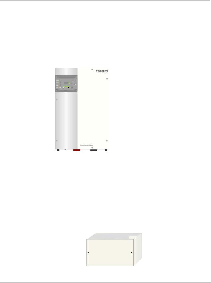
XW Inverter/Charger
The XW Inverter/Charger is a modular “building block” sine-wave inverter/charger that can be used for both residential and commercial stand-alone, grid-backup, and grid-tie applications with battery energy storage. The XW Series is a self-contained DC to AC inverter, battery charger, and AC transfer switch. Up to three inverters can be installed in parallel to create larger 120-240-volt, 3-wire, single-phase systems allowing for increased capacity.
Figure 1-2 XW Inverter/Charger
A Battery Temperature Sensor (FGA # 808-0232-02) is also included with the XW Inverter/Charger. The Battery Temperature Sensor monitors the temperature of the battery bank and adjusts the charging accordingly. See page 2–13 for installation instructions for this accessory.
XW Conduit Box
A conduit box (FGA # 865-1025) is available to enclose the bottom of the XW Inverter/Charger and protect the cabling. Use of the conduit box may be required depending on the local electrical code. Be sure to consult with the local electrical authority to ensure the installation is code-compliant.
Figure 1-3 XW Conduit Box
975-0239-01-01 |
1–3 |
Introduction
The XW Conduit Box comes in two pieces and mounts directly to the bottom of the inverter/charger with keyhole slots and screws. It is secured to the inverter by two #10-32 screws and is secured to the wall by two screws (not provided).
Internal wire barriers (or raceways) are included to keep communications wires separate from AC and DC power wires. The XW Conduit Box also includes multiple cable strap points.
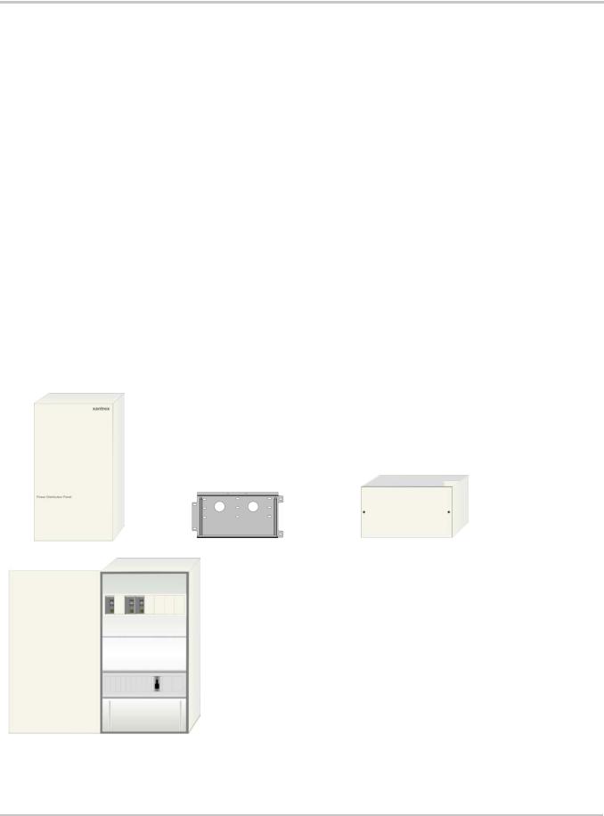
XW Power Distribution Panel Panel and XW Conduit Box
The XW Power Distribution Panel (FGA: 865-1015) includes a mounting plate and XW Conduit Box. It is factory wired and labelled with everything to support a code-compliant single-inverter installation. It is designed to mount on the right side of the inverter/charger, but it can also be configured to mount on the left side. Internal wiring and breakers can be added to expand the XW Power System with up to three inverters, four charge controllers, or other equipment to support 120/240-volt, 3-wire, single-phase systems.
The XW Power Distribution Panel and XW Conduit Box interface with:
•XW4024, XW4548, and XW6048 inverter/chargers
•XW Solar Charge Controllers (requires customer supplied breakers and wiring)
•C-Series Charge Controllers (requires customer supplied breakers and wiring).
Internal wire barriers (or raceways) are included to keep communications wires separate from AC and DC power wires.
XW Power Distribution Panel |
XW Power Distribution Panel includes: |
|
|
• Power Distribution Panel enclosure with a field-reversible panel door |
|
|
• |
Mounting Plate |
|
• |
XW Conduit Box |
XW Conduit Box
Mounting Plate
The enclosure comes pre-wired with:
•3x 60A, 120/240 Vac, 2-pole, Square-D, Type QOU, DIN-rail mounted AC breakers (pre-wired to connect to one XW inverter)
•1x GJ250A 160 Vdc, 3/8" stud DC breaker
•1x Ground terminal bus bar
•1x Neutral terminal bus bar
•1 pair #4/0 AWG Battery Cables
The panel door can be mounted on the right or left side of the XW Power
Distribution Panel.
AC Knockout slots = 8 (for dual 60A Square D, type QOU breakers)*
DC Knockout slots = 8 small (for 60A DC breakers) and 3 large (for GJ breakers)
XW PDP Dimensions:
30" (761mm) H x 16" (406mm) W x 8 ¼" (210mm) D Depth from the wall = 8 ¾" (223 mm)
*AC Breakers cannot exceed 60A.
Figure 1-4 Power Distribution Panel and XW Conduit Box
1–4 |
975-0239-01-01 |
System Components and Accessories
XW Connection Kit for INV2
The XW Connection Kit for Inv2 (FGA # 865-1020) is the extension kit required for connecting a second or third XW Inverter/Charger in the same system.
XW Conduit Box
Power Distribution Bars
#6 AWG AC Wiring
XW Connection Kit includes:
•XW Conduit Box with raceway barriers and cable strap connections points,
•3x 60 A, 120/240 Vac, 2-pole, Square-D, Type QOU, Din-Rail mountable, AC breakers (includes bypass plate)
•#6 AWG AC wiring to connect the inverter to the AC breakers (includes 4 conduit bushings)
•4x Power Distribution Bars (replaces factory-installed bars)
•1x GJ250A 160 Vdc, 3/8" stud DC breaker
•1x Bus Bar for DC positive
•1 pair #4/0 AWG battery cables
•AC Sync and Xanbus cables (not shown)
60A, 120/240Vac AC Breakers
AC Bypass Plate
15/16" bushing for AC sync and Xanbus knockouts
GJ250A DC breaker
1-3/8" bushings for AC Wiring knockouts
#4/0 AWG battery cables
DC Positive Bus Bar
Figure 1-5 XW Connection Kit for INV2
975-0239-01-01 |
1–5 |
Introduction
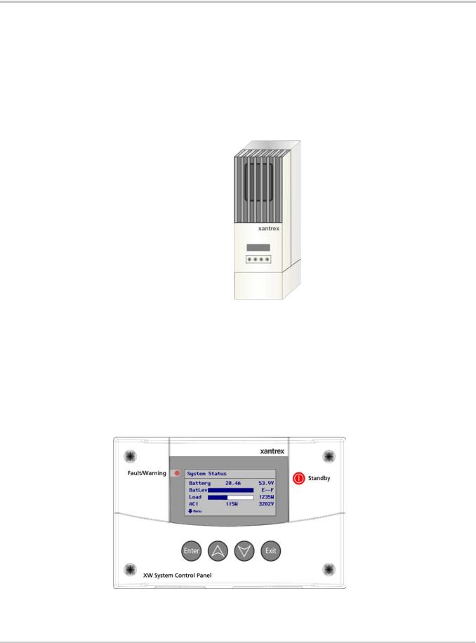
XW Solar Charge Controller
The XW Solar Charge Controller (FGA # 865-1030) is a 60 amp charge controller with integrated PVGFP and separate Battery Temperature Sensor. The XW Solar Charge Controller can be used with 12-, 24-, 36-, 48-, and 60-volt DC battery systems. However, the XW Inverter/Charger can only work at 24 or 48 volts depending on the model. When the XW Solar Charge Controller is used with the XW Inverter/Charger, it is limited to 24or 48-volt battery banks. The XW Solar Charge Controller will automatically detect the 24or 48-volt settings.
Figure 1-6 XW Solar Charge Controller
XW System Control Panel
The XW System Control Panel features a graphical, backlit liquid crystal display that displays system configuration and diagnostic information for all devices connected to the network. When installed as an XW Power System accessory, the XW System Control Panel eliminates the need for separate control panels for each device and gives a single point of control to set up and monitor an entire XW Power System.
FGA Number: 865-1050
Figure 1-7 XW System Control Panel
1–6 |
975-0239-01-01 |
System Components and Accessories
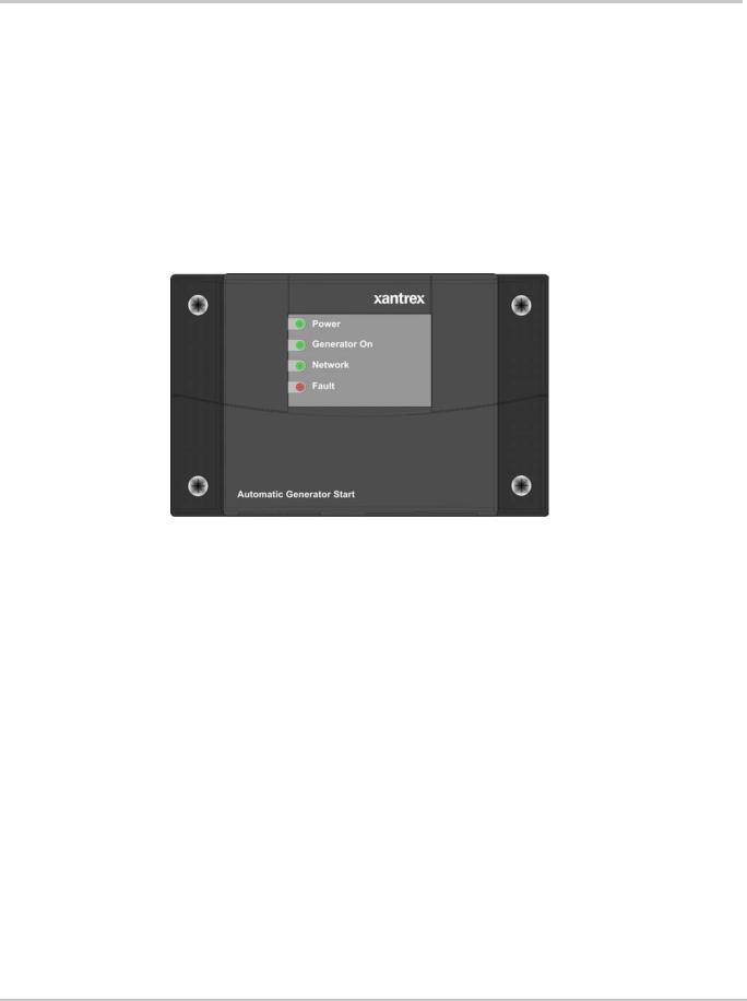
XW Automatic Generator Start
The XW Automatic Generator Start can automatically activate a generator to provide an XW Series Inverter/Charger with power to recharge depleted batteries or assist with heavy loads. The XW Automatic Generator Start adds intelligence to power management and eliminates time spent monitoring batteries and inverter loads.
The XW Automatic Generator Start is compatible with popular generators, and can be configured to start the generator in response to low battery voltage, thermostat operation, or load size on the inverter battery. A quiet time setting prevents the generator from starting at inconvenient times. LEDs display the status of the XW Automatic Generator Start, while all user-defined settings are programmed through the XW System Control Panel.
FGA Number: 865-1060
|
Figure 1-8 Automatic Generator Start |
|
Generator |
The generator should be a 120/240V, 2-wire or 3-wire generator with Auto Start capability. |
|
|
|
|
|
Important: Do not use a 120-volt only generator. The inverter will not accept |
|
|
power from a generator of this kind. |
|
|
The generator should also supply a Generator Run signal. This signal is used by the XW |
|
|
Automatic Generator Start to detect whether the generator is running. Some generator |
|
|
manufacturers refer to this signal as the Hour Meter Signal or Switched B+. |
|
Generator |
The XW Automatic Generator Start supports most two and three-wire generator starters. |
|
Compatibility |
Some manufacturers include, but are not limited to, Onan (Quiet Diesel, gasoline, and LP), |
|
|
Power Tech, Generac, Northern Lights, Fisher Panda, Westerbeke, Kohler, Honda, and |
|
|
Yamaha. Check with the generator manufacturer to ensure the generator in question |
|
|
includes automatic starting capabilities. |
|
XW System Control |
A XW System Control Panel is required to configure the XW Automatic Generator Start |
|
Panel |
and monitor generator starting and stopping activity. |
|
|
The XW System Control Panel also provides real-time clock information for the XW |
|
|
Automatic Generator Start Quiet Time and Exercise Time features. |
|
975-0239-01-01 |
1–7 |
1–8
2 Inverter/ChargerInstallation
Chapter 2, “Inverter/Charger Installation” describes how to mount and install the XW Inverter/Charger, and the XW Power Distribution Panel and XW Conduit Box.
For this Topic |
See.... |
|
|
“Pre-Installation” |
page 2–2 |
|
|
“Step 1: Installing the Mounting Plate” |
page 2–4 |
|
|
“Step 2: Mounting the Inverter” |
page 2–6 |
|
|
“Step 3: Mounting the XW Power Distribution Panel and XW |
page 2–7 |
Conduit Box” |
|
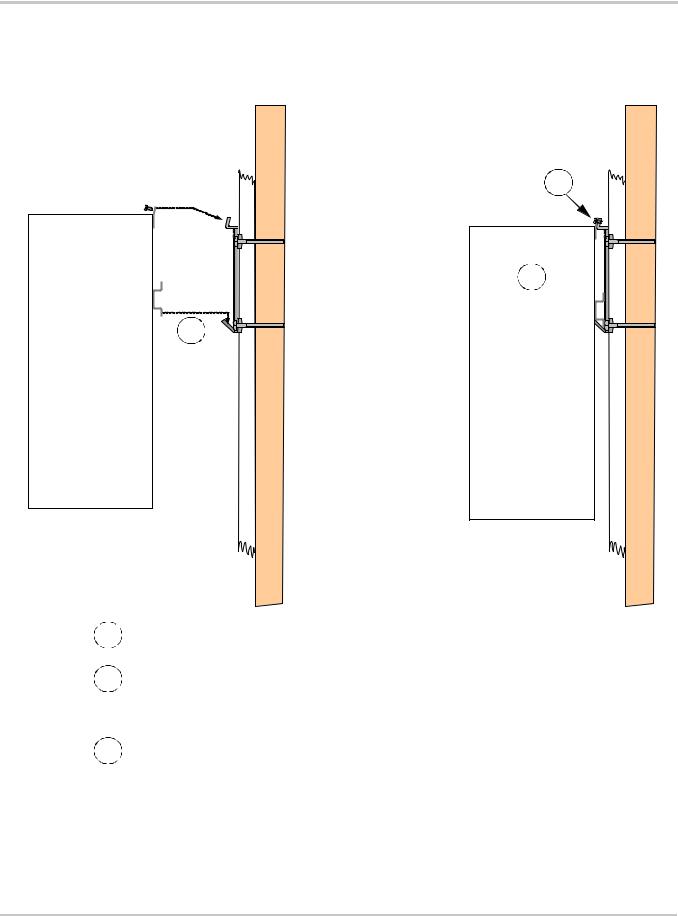
|
|
“Step 4: Wiring the Inverter” |
page 2–8 |
|
|
“Step 5: Installing Additional Inverters” |
page 2–29 |
|
|
Inverter/Charger Installation
Pre-Installation
Before installing the XW Inverter/Charger, read all instructions and cautionary markings located in this manual.
Important: Be sure to obtain the appropriate permits, if necessary, prior to starting this installation. Installations must meet all local codes and standards.
Installations of this equipment should only be performed by skilled personnel such as qualified electricians and Certified Renewable Energy (RE) System installers.
|
WARNING: Personal Injury |
|
The XW Inverter/Charger weighs approximately 120 pounds (54 kg). To prevent personal injury, |
|
always use proper lifting techniques and have someone available to assist with lifting during |
|
installation. |
Location |
|
|
|
|
The XW Inverter/Charger is certified for indoor (heated or unheated) installations only. |
Close to battery |
Locate the inverter as close to the batteries as possible in order to keep the battery cable |
bank |
length short. The maximum recommended battery cable length is 10 feet (3 m). |
|
WARNING: Explosion and Corrosion Hazard |
|
Do not locate the inverter directly above the batteries or in the same compartment as vented |
|
batteries. |
|
|
|
Locate any electronic equipment susceptible to radio frequency and electromagnetic |
|
interference as far away from the inverter as possible. |
Fire safety |
Do not locate the inverter near readily flammable materials such as cloth, paper, straw, or |
|
plastic sheeting. Flammable materials should be kept a minimum distance of 24 inches |
|
(60 cm) from the top surface and 12 inches (30 cm) from either side surface and the front |
|
of the XW Inverter/Charger. |
Knockout Preparation
Remove your choice of knockouts from the chassis to facilitate conduit installation for wire runs. Ensure no debris from this procedure remains inside the inverter enclosure.
Important: Do not drill, cut, or punch holes into the XW power distribution
Panel. Use only the knockouts provided for conduit entry.
2–2 |
975-0239-01-01 |
Pre-Installation
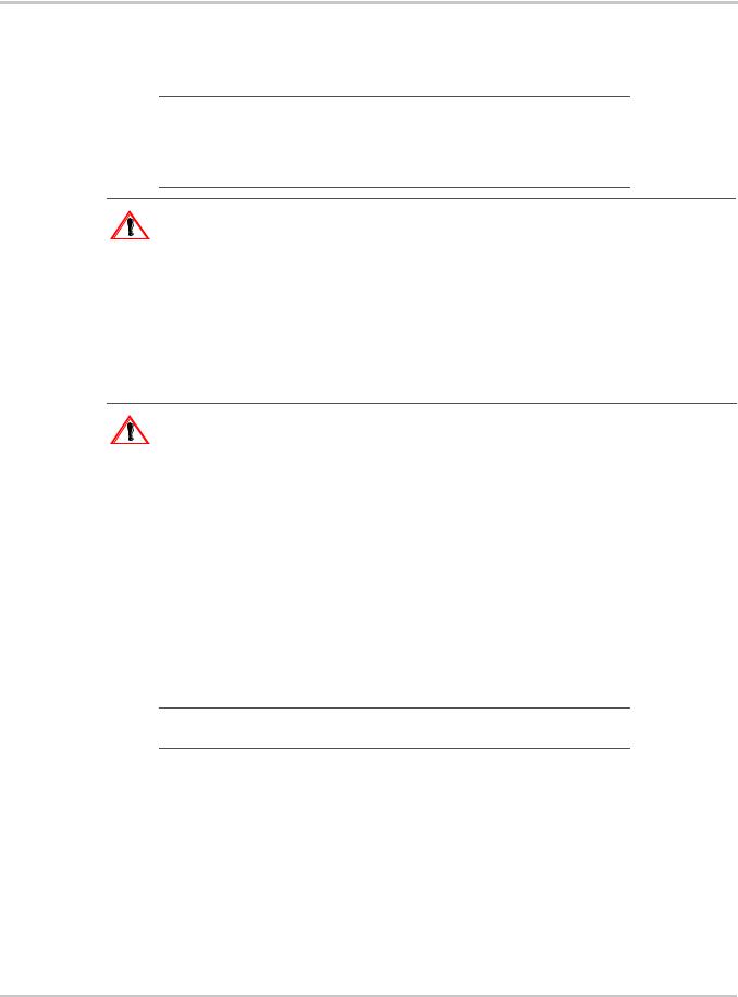
Clearance Requirements
Provide a minimum clearance of 6 inches (15 cm)—12 inches is preferred—around the top and 6 inches (15 cm) at the bottom of the inverter for ventilation. There must be at least three feet of clearance in front of the inverter. Ensure that the vents are not obstructed with foreign objects and that the minimum clearances are met.
Figure 2-1 Clearance Requirements
Mounting
The XW Power System is designed to be mounted on a vertical surface. The supporting surface must be strong enough to support a minimum of 500 pounds (227 kg). To facilitate installation, a wall mounting plate (Xantrex p/n 210-0462-01-01) is provided for each XW Inverter/Charger and XW Power Distribution Panel. The mounting plate and hardware on the XW Inverter/Charger and XW Power Distribution Panel are designed to meet standards for structural and seismic stability. When properly installed, the system also meets Section 59 of UL 1741 for Static Loads.
975-0239-01-01 |
2–3 |
Inverter/Charger Installation
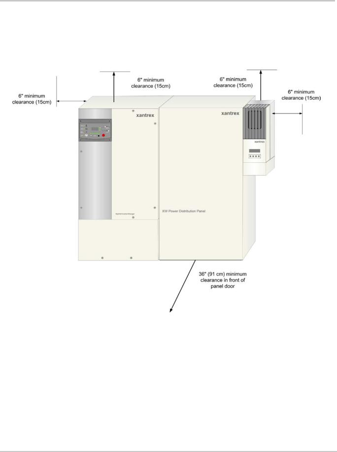
Step 1: Installing the Mounting Plate
Each XW Inverter/Charger and XW Power Distribution Panel requires a separate mounting plate. This bracket is first attached to the wall, then the inverter/charger or distribution panel is attached to the wall bracket.
The wall bracket is attached to the wall with lag bolts or other fasteners, provided by the installer. A minimum of four ¼-inch diameter fasteners are required. The fasteners must be sufficiently strong to support 500 pounds.
The wall bracket has mounting holes spaced 16 inches (40 cm) apart and is designed to span two wall studs spaced 16 inches on-center. Additional mounting holes are also provided for flexibility in mounting options. If the wall does not have 16-inch on-center studs, the installer will need to provide adequate supports for the brackets. For example, a sheet of plywood can be attached to the wall, and the wall brackets can then be attached to plywood.
Both the XW Inverter/Charger and XW Power Distribution Panel use the same wall bracket. The brackets are designed to interlock (as shown in Figure 2-3), so that additional mounting plates are easily installed without additional measuring or levelling.
The type of fastener required to secure the mounting plate varies according to the vertical surface and wall structure of your installation location.
Table 2-1 Mounting Plate Fastener Recommendations
|
|
Number of Screws |
Structure |
Required Fastener |
Per Bracket |
|
|
|
Wood studs at 16" (on center - O.C.) |
1/4" Ø × 3 1/2" long lag screw |
Four |
Wood studs not at 16" O.C. (3/4" minimum |
1/4" Ø × 1" long wood screw |
Six |
plywood panel required) |
|
|
Steel studs at 16" O.C. (minimum 18 gauge) |
1/4" Ø self-drilling screw |
Four |
|
|
|
16 (406)
|
|
|
|
|
|
|
|
|
|
|
|
|
|
|
1 3/4 (45) |
|
|
|
|
|
|
|
|
|
|
|
|
||
|
|
|
|
|
|
|
|
|
|
|
|
|
|
|
|
|
|
|
|
|
|
|
|
|
|
|
|||
|
|
|
|
|
|
|
|
|
|
|
|
|
|
|
|
|
|
|
|
|
|
|
|
||||||
4 1/2 |
(115) |
|
|
|
|
|
|
|
|
|
|
|
|
||||||||||||||||
|
|
|
|
|
|
|
6 7/8 |
|
|
|
9 3/16 |
|
|||||||||||||||||
|
|
|
|
|
|
|
|
|
|
6 (153) |
|
|
|
|
|
|
|
|
(175) |
|
|
|
(233) |
|
|||||
|
|
|
|
|
|
|
|
|
|
|
|
|
|
|
|
|
|
|
|
|
|
|
|
|
|
||||
|
|
|
2 1/4 |
|
|
|
|
|
|
|
|
|
|
|
|
|
|
|
|
|
|
||||||||
|
|
|
|
|
(57) |
|
|
|
|
|
|
|
|
|
|
|
|
|
|
|
|
|
|
|
|
|
|||
|
|
|
|
|
|
|
|
|
|
|
|
|
|
|
|
|
|
|
|
|
|
|
|||||||
|
|
|
|
|
|
|
|
|
|
|
|
|
|
|
|
|
|
|
|
|
|
|
|
|
|
|
|
|
|
|
|
|
|
|
|
|
|
|
|
|
|
|
|
|
|
|
|
|
|
|
|
|
|
|
|
|
|||
2 (49) |
|
|
|
|
|
|
|
|
|
|
|
|
|
|
|
|
|
|
|
|
|
|
|
|
|
|
|||
|
|
|
|
|
|
|
|
|
|
|
|
|
|
|
|
|
|
|
|
|
|
|
|
|
|
|
|||
|
|
|
|
|
|
|
|
|
|
|
|
|
|
|
|
|
|
|
|
|
|
3/4 (19) |
|
|
|
|
|||
|
|
|
|
|
|
|
|
|
|
|
|
|
|
|
|
|
|
|
|
|
|
|
|
|
|
|
|||
|
|
|
|
|
|
|
|
|
|
|
|
|
|
|
|
|
|
|
|
|
|
|
|||||||
|
|
|
|
|
|
|
|
|
|
|
|
|
|
|
|
|
|
|
|
|
|
|
|
|
|
|
|
|
|
|
|
|
|
|
|
|
|
|
|
|
|
|
|
|
|
|
|
|
|
|
|
|
|
|
|
|
|
|
|
|
|
|
|
|
|
|
|
|
|
|
|
|
17 (432) |
|
|
all measurements in inches |
|||||||||||||
|
|
|
|
|
|
|
|
|
|
|
|
|
|
|
|||||||||||||||
|
|
|
|
|
|
|
|
|
|
|
|
|
|
|
|
|
|
|
(millimeters) |
|
|
|
|||||||
Figure 2-2 Mounting Plate Dimensions
2–4 |
975-0239-01-01 |
Step 1: Installing the Mounting Plate
Wall studs 16" on center behind wallboard
Side View
2 × 4 wall stud
Wallboard
Plywood (optional)
mounting plate
60" (152.4 cm) from floor puts the inverter display panel at approx. 65" high.
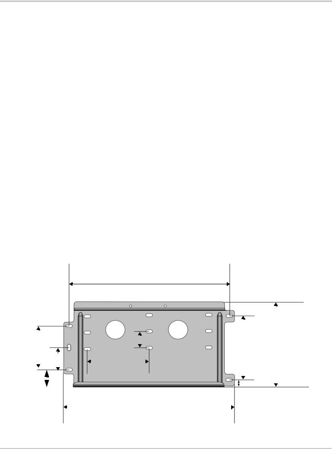
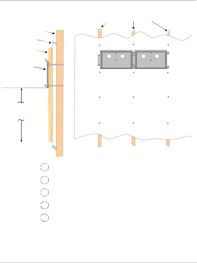
Multiple mounting plates should fit together as shown.
Add ¾" plywood if additional support is needed.
1Locate the wall studs.
2If necessary, enhance the support surface with a ¾" plywood panel secured to the wall studs. Plywood should span at least three wall studs.
3Use hardware sized to support a minimum of 500 lbs (not provided) to secure the plywood to the wall.
4Using a level, secure the first mounting bracket to the wall. Use recommended anchoring hardware to secure the plate (see Table 2-1).
5Mount the next bracket adjacent to the first one. The brackets are designed to interlock, so additional mounting brackets are easily installed without additional measuring or levelling.
Figure 2-3 Mounting the Bracket for the XW Inverter/Charger or Distribution Panel
975-0239-01-01 |
2–5 |
Inverter/Charger Installation
Step 2: Mounting the Inverter
3
2
1
1Align the flange on the back of the XW Inverter/Charger with the bottom edge of the mounting plate.
2
3
Lower the flange on the inverter onto the mounting plate.
CAUTION: Before releasing the full weight of the unit, ensure the inverter is seated properly on the mounting plate.
Secure the top of inverter with two #10 self-tapping screws (supplied).
Figure 2-4 Mounting the XW Inverter/Charger
2–6 |
975-0239-01-01 |
 Loading...