


 Loading...
Xantrex Technology XPR 20-300, XPR 150-40, XPR 60-100, XPR 40-150, XPR 80-75 User Manual
...XPR 10-600
XPR 20-300
XPR 30-200
XPR 40-150
XPR 60-100
XPR 80-75
XPR 100-60
XPR 150-40
XPR 300-20
XPR 600-10
Operating Manual
XPR 6000 Watt Series
Programmable DC
Power Supply

Operating Manual for
XPR 6000 Watt Series
Programmable DC
Power Supply
Limited
Warranty
What does this warranty cover and how long does it last?
This Limited Warranty is provided by Xantrex Technology, Inc. (“Xantrex”) and covers defects in workmanship and materials in your XPR 6000 Watt Series DC Power Supply. This warranty lasts for a Warranty Period of 5 years from the date of purchase at point of sale to you, the original end user customer.
What will Xantrex do?
Xantrex will, at its option, repair or replace the defective product free of charge, provided that you notify Xantrex of the product defect within the Warranty Period, and provided that Xantrex through inspection establishes the existence of such a defect and that it is covered by this Limited Warranty.
Xantrex will, at its option, use new and/or reconditioned parts in performing warranty repair and building replacement products. Xantrex reserves the right to use parts or products of original or improved design in the repair or replacement. If Xantrex repairs or replaces a product, its warranty continues for the remaining portion of the original Warranty Period or 90 days from the date of the return shipment to the customer, whichever is greater. All replaced products and all parts removed from repaired products become the property of Xantrex.
Xantrex covers both parts and labor necessary to repair the product, and return shipment to the customer via a Xantrex-selected non-expedited surface freight within the contiguous United States and Canada. Alaska and Hawaii are excluded. Contact Xantrex Customer Service for details on freight policy for return shipments outside of the contiguous United States and Canada.
How do you get service?
If your product requires troubleshooting or warranty service, contact your merchant. If you are unable to contact your merchant, or the merchant is unable to provide service, contact Xantrex directly at:
Phone: |
604 422 8595 |
Toll Free North America: |
1 800 667 8422 |
Fax: |
604 421 3056 |
Email: |
prg.info@xantrex.com |
ii |
Operating Manual for XPR Series Power Supply |
Direct returns may be performed according to the Xantrex Return Material Authorization Policy described in your product manual. For some products, Xantrex maintains a network of regional Authorized Service Centers. Call Xantrex or check our website to see if your product can be repaired at one of these facilities.
In any warranty claim, dated proof of purchase must accompany the product and the product must not have been disassembled or modified without prior written authorization by Xantrex.
Proof of purchase may be in any one of the following forms:
•The dated purchase receipt from the original purchase of the product at point of sale to the end user, or
•The dated dealer invoice or purchase receipt showing original equipment manufacturer (OEM) status, or
•The dated invoice or purchase receipt showing the product exchanged under warranty
What does this warranty not cover?
This Limited Warranty does not cover normal wear and tear of the product or costs related to the removal, installation, or troubleshooting of the customer’s electrical systems. This warranty does not apply to and Xantrex will not be responsible for any defect in or damage to:
a.the product if it has been misused, neglected, improperly installed, physically damaged or altered, either internally or externally, or damaged from improper use or use in an unsuitable environment;
b.the product if it has been subjected to fire, water, generalized corrosion, biological infestations, and high input voltage from lightning strikes;
c.the product if repairs have been done to it other than by Xantrex or its authorized service centers (hereafter “ASCs”);
d.the product if it is used as a component part of a product expressly warranted by another manufacturer;
e.the product if its original identification (trade-mark, serial number) markings have been defaced, altered, or removed.
Release 1.1 |
iii |
Disclaimer Product
THIS LIMITED WARRANTY IS THE SOLE AND EXCLUSIVE WARRANTY PROVIDED BY XANTREX IN CONNECTION WITH YOUR XANTREX PRODUCT AND IS, WHERE PERMITTED BY LAW, IN LIEU OF ALL OTHER WARRANTIES, CONDITIONS, GUARANTEES, REPRESENTATIONS, OBLIGATIONS AND LIABILITIES, EXPRESS OR IMPLIED, STATUTORY OR OTHERWISE IN CONNECTION WITH THE PRODUCT, HOWEVER ARISING (WHETHER BY CONTRACT, TORT, NEGLIGENCE, PRINCIPLES OF MANUFACTURER’S LIABILITY, OPERATION OF LAW, CONDUCT, STATEMENT OR OTHERWISE), INCLUDING WITHOUT RESTRICTION ANY IMPLIED WARRANTY OR CONDITION OF QUALITY, MERCHANTABILITY OR FITNESS FOR A PARTICULAR PURPOSE. ANY IMPLIED WARRANTY OF MERCHANTABILITY OR FITNESS FOR A PARTICULAR PURPOSE TO THE EXTENT REQUIRED UNDER APPLICABLE LAW TO APPLY TO THE PRODUCT SHALL BE LIMITED IN DURATION TO THE PERIOD STIPULATED UNDER THIS LIMITED WARRANTY.
IN NO EVENT WILL XANTREX BE LIABLE FOR ANY SPECIAL, DIRECT, INDIRECT, INCIDENTAL OR CONSEQUENTIAL DAMAGES, LOSSES, COSTS OR EXPENSES HOWEVER ARISING WHETHER IN CONTRACT OR TORT INCLUDING WITHOUT RESTRICTION ANY ECONOMIC LOSSES OF ANY KIND, ANY LOSS OR DAMAGE TO PROPERTY, ANY PERSONAL INJURY, ANY DAMAGE OR INJURY ARISING FROM OR AS A RESULT OF MISUSE OR ABUSE, OR THE INCORRECT INSTALLATION, INTEGRATION OR OPERATION OF THE PRODUCT.
Exclusions If this product is a consumer product, federal law does not allow an exclusion of implied warranties. To the extent you are entitled to implied warranties under federal law, to the extent permitted by applicable law they are limited to the duration of this Limited Warranty. Some states and provinces do not allow limitations or exclusions on implied warranties or on the duration of an implied warranty or on the limitation or exclusion of incidental or consequential damages, so the above limitation(s) or exclusion(s) may not apply to you. This Limited Warranty gives you specific legal rights. You may have other rights which may vary from state to state or province to province.
iv |
Operating Manual for XPR Series Power Supply |
Information WITHOUT LIMITING THE GENERALITY OF THE FOREGOING, UNLESS SPECIFICALLY AGREED TO BY IT IN WRITING, XANTREX
a.MAKES NO WARRANTY AS TO THE ACCURACY, SUFFICIENCY OR SUITABILITY OF ANY TECHNICAL OR OTHER INFORMATION PROVIDED IN MANUALS OR OTHER DOCUMENTATION PROVIDED BY IT IN CONNECTION WITH THE PRODUCT; AND
b.ASSUMES NO RESPONSIBILITY OR LIABILITY FOR LOSSES, DAMAGES, COSTS OR EXPENSES, WHETHER SPECIAL, DIRECT, INDIRECT, CONSEQUENTIAL OR INCIDENTAL, WHICH MIGHT ARISE OUT OF THE USE OF SUCH INFORMATION.
THE USE OF ANY SUCH INFORMATION WILL BE ENTIRELY AT THE USER’S RISK.
WARNING: Limitations on Use
Please refer to your product user manual for limitations on uses of the product. Specifically, please note that this power supply is not intended for use in connection with life support systems and Xantrex makes no warranty or representation in connection with any use of the product for such purposes.
Xantrex Technology, Inc.
8999 Nelson Way
Burnaby, British Columbia
Canada V5A 4B5
Information
About Your
Power
Supply
Please record the following information when you first open your Power Supply package:
Model Number |
______________________________________________ |
Serial Number |
______________________________________________ |
Purchased From |
______________________________________________ |
Purchase Date |
______________________________________________ |
Release Release 1.1 (2003-04)
Copyright © 2002 Xantrex Technology Inc. All rights reserved. Printed in Canada
Release 1.1 |
v |

Warnings,
Cautions,
and Notes
Warnings, cautions, and notes are defined and formatted in this manual as shown below.
WARNING
Describes a potential hazard which could result in injury or death, or, a procedure which, if not performed correctly, could result in injury or death.
CAUTION
Describes a procedure which, if not performed correctly, could result in damage to data, equipment, or systems.
Note
Describes additional operating information which may affect the performance of the equipment.
Power
Supply |
|
WARNING—High Energy and High Voltage |
|
Safety |
|
Exercise caution when using and calibrating a power supply. High energy levels |
|
|
|
can be stored at the output voltage terminals on a power supply in normal |
|
|
|
operation. In addition, potentially lethal voltages exist in the power circuit and on |
|
|
|
the output and sense connectors of a power supply with a rated output greater |
|
|
|
than 40 V. Filter capacitors store potentially dangerous energy for some time after |
|
|
|
power is removed. |
|
|
|
|
|
|
|
|
|
|
|
CAUTION |
|
|
|
||
|
|
Operate the power supply in an environment free of flammable gases or fumes. |
|
|
|
To ensure that the power supply’s safety features are not compromised, use the |
|
|
|
power supply as specified in this manual and do not substitute parts or make any |
|
|
|
unauthorized modifications. Contact the service technician for service and repair |
|
|
|
help. Repairs must be made by experienced service technicians only. |
|
|
|
|
|
vi |
Operating Manual for XPR Series Power Supply |
About This Manual
Who Should Use This Manual
Navigation
Sections
Revisions
This manual is designed for users who understand basic electrical theory, especially as applied to the operation of power supplies. This implies a recognition of constant voltage and constant current operating modes and the control of input and output power, as well as the observance of safe techniques while making connections to the supply and any changes in settings.
To help you locate information easily, this manual has the following:
•A Table of Contents
•A List of Figures
•A List of Tables
Section 1 About the XPR Power Supply describes the power supply features, front panel controls, front panel display, and rear panel connectors. It also gives an overview of operation.
Section 2 Installation describes how to mount the power supply, how to connect it, and how to run initial tests.
Section 3 Operation describes basic operation and functions carried out from the front panel.
Section 4 Remote Operation explains how to hook up the remote analog interface.
Appendix A Specifications and Characteristics provides electrical and mechanical specifications.
The current release of this manual is listed below. Updates may be issued as an addendum.
Release 1.1 (2003-04)
Release 1.1 |
vii |
About This Manual
viii |
Operating Manual for XPR Series Power Supply |
Contents
About This Manual . . . . . . . . . . . . . . . . . . . . . . . . . . . . . . . . . . . . . . . . . . . . . . . . . . . vii Contents . . . . . . . . . . . . . . . . . . . . . . . . . . . . . . . . . . . . . . . . . . . . . . . . . . . . . . . . . . . .ix List of Tables . . . . . . . . . . . . . . . . . . . . . . . . . . . . . . . . . . . . . . . . . . . . . . . . . . . . . . .xiii List of Figures . . . . . . . . . . . . . . . . . . . . . . . . . . . . . . . . . . . . . . . . . . . . . . . . . . . . . . . xv
Section 1. About The XPR Power Supply
Overview. . . . . . . . . . . . . . . . . . . . . . . . . . . . . . . . . . . . . . . . . . . . . . . . . . . . . . . . . . . 17
Features and Options. . . . . . . . . . . . . . . . . . . . . . . . . . . . . . . . . . . . . . . . . . . . . 17
Front Panel . . . . . . . . . . . . . . . . . . . . . . . . . . . . . . . . . . . . . . . . . . . . . . . . . . . . . . . . . 18
Status Annunciators . . . . . . . . . . . . . . . . . . . . . . . . . . . . . . . . . . . . . . . . . . . . . . . . . . 19
Rear Panel Connectors and Switch . . . . . . . . . . . . . . . . . . . . . . . . . . . . . . . . . . . . . . 20
Rear Panel S1 Switch . . . . . . . . . . . . . . . . . . . . . . . . . . . . . . . . . . . . . . . . . . . . 20
Rear Panel J1 Connector. . . . . . . . . . . . . . . . . . . . . . . . . . . . . . . . . . . . . . . . . . 22
Section 2. Installation
Overview. . . . . . . . . . . . . . . . . . . . . . . . . . . . . . . . . . . . . . . . . . . . . . . . . . . . . . . . . . . 25 Basic Setup Procedure . . . . . . . . . . . . . . . . . . . . . . . . . . . . . . . . . . . . . . . . . . . . . . . . 25
Inspection, Cleaning, and Packaging . . . . . . . . . . . . . . . . . . . . . . . . . . . . . . . . . . . . . 26 Initial Inspection . . . . . . . . . . . . . . . . . . . . . . . . . . . . . . . . . . . . . . . . . . . . . . . . . 26 Maintenance. . . . . . . . . . . . . . . . . . . . . . . . . . . . . . . . . . . . . . . . . . . . . . . . . . . . 26
Returning Power Supplies to the Manufacturer . . . . . . . . . . . . . . . . . . . . . . . . . . . . . 27 Return Material Authorization Policy . . . . . . . . . . . . . . . . . . . . . . . . . . . . . . . . . 27 Packaging for Shipping or Storage . . . . . . . . . . . . . . . . . . . . . . . . . . . . . . . . . . 28
Location, Mounting, and Ventilation . . . . . . . . . . . . . . . . . . . . . . . . . . . . . . . . . . . . . . 29 Rack Mounting . . . . . . . . . . . . . . . . . . . . . . . . . . . . . . . . . . . . . . . . . . . . . . . . . . 29 Ventilation . . . . . . . . . . . . . . . . . . . . . . . . . . . . . . . . . . . . . . . . . . . . . . . . . . . . . 31
AC Input Power. . . . . . . . . . . . . . . . . . . . . . . . . . . . . . . . . . . . . . . . . . . . . . . . . . . . . . 32 AC Input Connector . . . . . . . . . . . . . . . . . . . . . . . . . . . . . . . . . . . . . . . . . . . . . . 32 AC Input Wire. . . . . . . . . . . . . . . . . . . . . . . . . . . . . . . . . . . . . . . . . . . . . . . . . . . 33 AC Wire Input Connection . . . . . . . . . . . . . . . . . . . . . . . . . . . . . . . . . . . . . . . . . 33
Basic Tests . . . . . . . . . . . . . . . . . . . . . . . . . . . . . . . . . . . . . . . . . . . . . . . . . . . . . . . . . 35 Equipment Required . . . . . . . . . . . . . . . . . . . . . . . . . . . . . . . . . . . . . . . . . . . . . 35 Power ON Check . . . . . . . . . . . . . . . . . . . . . . . . . . . . . . . . . . . . . . . . . . . . . . . . 36 Voltage Mode Operation Check. . . . . . . . . . . . . . . . . . . . . . . . . . . . . . . . . . . . . 37 Current Mode Operation Check . . . . . . . . . . . . . . . . . . . . . . . . . . . . . . . . . . . . . 37 Front Panel Function Checks. . . . . . . . . . . . . . . . . . . . . . . . . . . . . . . . . . . . . . . 38
Load Wiring. . . . . . . . . . . . . . . . . . . . . . . . . . . . . . . . . . . . . . . . . . . . . . . . . . . . . . . . . 39 Current Carrying Capacity . . . . . . . . . . . . . . . . . . . . . . . . . . . . . . . . . . . . . . . . . 39 Load Wiring Length for Operation with Sense Lines . . . . . . . . . . . . . . . . . . . . . 40 Noise and Impedance Effects . . . . . . . . . . . . . . . . . . . . . . . . . . . . . . . . . . . . . . 40
Load Connections. . . . . . . . . . . . . . . . . . . . . . . . . . . . . . . . . . . . . . . . . . . . . . . . . . . . 41 Wire Size . . . . . . . . . . . . . . . . . . . . . . . . . . . . . . . . . . . . . . . . . . . . . . . . . . . . . . 41
Release 1.1 |
ix |
Contents
Isolation. . . . . . . . . . . . . . . . . . . . . . . . . . . . . . . . . . . . . . . . . . . . . . . . . . . . . . . 41
Single Load . . . . . . . . . . . . . . . . . . . . . . . . . . . . . . . . . . . . . . . . . . . . . . . . . . . . 42
Multiple Loads . . . . . . . . . . . . . . . . . . . . . . . . . . . . . . . . . . . . . . . . . . . . . . . . . . 43
Output Strain Relief/Cover . . . . . . . . . . . . . . . . . . . . . . . . . . . . . . . . . . . . . . . . 44
Remote Sensing . . . . . . . . . . . . . . . . . . . . . . . . . . . . . . . . . . . . . . . . . . . . . . . . . . . . 45
Section 3. Operation
Overview . . . . . . . . . . . . . . . . . . . . . . . . . . . . . . . . . . . . . . . . . . . . . . . . . . . . . . . . . . 47 Powering ON the Power Supply . . . . . . . . . . . . . . . . . . . . . . . . . . . . . . . . . . . . 47
Power Supply Operating States. . . . . . . . . . . . . . . . . . . . . . . . . . . . . . . . . . . . . . . . . 48 Power-On . . . . . . . . . . . . . . . . . . . . . . . . . . . . . . . . . . . . . . . . . . . . . . . . . . . . . 48 Output Shutdown. . . . . . . . . . . . . . . . . . . . . . . . . . . . . . . . . . . . . . . . . . . . . . . . 48 Soft Start . . . . . . . . . . . . . . . . . . . . . . . . . . . . . . . . . . . . . . . . . . . . . . . . . . . . . . 48 Normal Operation . . . . . . . . . . . . . . . . . . . . . . . . . . . . . . . . . . . . . . . . . . . . . . . 48
Power Supply Regulation Modes. . . . . . . . . . . . . . . . . . . . . . . . . . . . . . . . . . . . . . . . 49 Constant Voltage (CV) . . . . . . . . . . . . . . . . . . . . . . . . . . . . . . . . . . . . . . . . . . . 49 Constant Current (CC) . . . . . . . . . . . . . . . . . . . . . . . . . . . . . . . . . . . . . . . . . . . 49 Automatic Mode Crossover. . . . . . . . . . . . . . . . . . . . . . . . . . . . . . . . . . . . . . . . 49
Remote Control Modes . . . . . . . . . . . . . . . . . . . . . . . . . . . . . . . . . . . . . . . . . . . . . . . 49
Front Panel Controls . . . . . . . . . . . . . . . . . . . . . . . . . . . . . . . . . . . . . . . . . . . . . . . . . 50 Function Buttons . . . . . . . . . . . . . . . . . . . . . . . . . . . . . . . . . . . . . . . . . . . . . . . . 50
Using Over Voltage Protection (OVP) . . . . . . . . . . . . . . . . . . . . . . . . . . . . . . . . . . . . 51 Front Panel OVP Operation . . . . . . . . . . . . . . . . . . . . . . . . . . . . . . . . . . . . . . . 51 Resetting the OVP Circuit . . . . . . . . . . . . . . . . . . . . . . . . . . . . . . . . . . . . . . . . . 52
Using the Shutdown Function (Output ON/OFF) . . . . . . . . . . . . . . . . . . . . . . . . . . . . 53 Controlling Output ON/OFF via Front Panel . . . . . . . . . . . . . . . . . . . . . . . . . . . 53 Controlling the Interlock Function via the J1 Connector . . . . . . . . . . . . . . . . . . 53
Over Temperature Protection (OTP) . . . . . . . . . . . . . . . . . . . . . . . . . . . . . . . . . . . . . 54
User Diagnostics . . . . . . . . . . . . . . . . . . . . . . . . . . . . . . . . . . . . . . . . . . . . . . . . . . . . 55 Emergency Shutdown . . . . . . . . . . . . . . . . . . . . . . . . . . . . . . . . . . . . . . . . . . . . 55 Unusual or Erratic Operation. . . . . . . . . . . . . . . . . . . . . . . . . . . . . . . . . . . . . . . 55 Troubleshooting for Operators . . . . . . . . . . . . . . . . . . . . . . . . . . . . . . . . . . . . . 55
Alarms . . . . . . . . . . . . . . . . . . . . . . . . . . . . . . . . . . . . . . . . . . . . . . . . . . . . . . . . . . . . 57
Section 4. Remote Operation
Introduction . . . . . . . . . . . . . . . . . . . . . . . . . . . . . . . . . . . . . . . . . . . . . . . . . . . . . . . . 59
Making Connections for Remote Control . . . . . . . . . . . . . . . . . . . . . . . . . . . . . . . . . . 60 Remote Shutdown Using a Contact Closure. . . . . . . . . . . . . . . . . . . . . . . . . . . 60
Remote Analog Programming of Output Voltage and Current Limit . . . . . . . . . . . . . 61 Remote Programming Options . . . . . . . . . . . . . . . . . . . . . . . . . . . . . . . . . . . . . 61
Select Remote Control Function . . . . . . . . . . . . . . . . . . . . . . . . . . . . . . . . . . . . . . . . 61 Remote Analog Programming Procedure . . . . . . . . . . . . . . . . . . . . . . . . . . . . . 62
Remote Monitoring of Output Voltage and Current . . . . . . . . . . . . . . . . . . . . . . . . . . 64 Readback Signals . . . . . . . . . . . . . . . . . . . . . . . . . . . . . . . . . . . . . . . . . . . . . . . 64
x |
Operating Manual for XPR Series Power Supply |
Contents
Appendix A. Specifications and Characteristics
Electrical Specifications—Summary . . . . . . . . . . . . . . . . . . . . . . . . . . . . . . . . . . . . . . 66
AC Line Input Specifications. . . . . . . . . . . . . . . . . . . . . . . . . . . . . . . . . . . . . . . . . . . . 70
AC Line Input Voltage Operating Ranges . . . . . . . . . . . . . . . . . . . . . . . . . . . . . 70
Output Performance Specifications . . . . . . . . . . . . . . . . . . . . . . . . . . . . . . . . . . . . . . 71
Environmental Specification . . . . . . . . . . . . . . . . . . . . . . . . . . . . . . . . . . . . . . . . . . . . 75
Thermal Specification. . . . . . . . . . . . . . . . . . . . . . . . . . . . . . . . . . . . . . . . . . . . . 75
Humidity Specification . . . . . . . . . . . . . . . . . . . . . . . . . . . . . . . . . . . . . . . . . . . . 75
Approvals . . . . . . . . . . . . . . . . . . . . . . . . . . . . . . . . . . . . . . . . . . . . . . . . . . . . . . 75
Mechanical Specification . . . . . . . . . . . . . . . . . . . . . . . . . . . . . . . . . . . . . . . . . . . . . . 76
Release 1.1 |
xi |
Contents
xii |
Operating Manual for XPR Series Power Supply |
List of Tables
Table 1.1 Rear Panel S1 Switch Assignments . . . . . . . . . . . . . . . . . . . . . . . . . . 21 Table 1.2 Rear Panel J1 Connector Terminals and Functions . . . . . . . . . . . . . . 23 Table 2.1 Basic Setup Procedure . . . . . . . . . . . . . . . . . . . . . . . . . . . . . . . . . . . . 25 Table 2.2 AC Wire Specification for 6000 Watt units. . . . . . . . . . . . . . . . . . . . . . 33 Table 2.3 Current Carrying Capacity for Load Wiring . . . . . . . . . . . . . . . . . . . . . 39 Table 3.1 Switch Settings for Interlock Circuit Logic . . . . . . . . . . . . . . . . . . . . . . 53 Table 3.2 Switch Settings for Over Temperature Recovery Options. . . . . . . . . . 54 Table 3.3 User Diagnostics . . . . . . . . . . . . . . . . . . . . . . . . . . . . . . . . . . . . . . . . . 56 Table 4.1 Analog Pin Connections with a Contact Closure . . . . . . . . . . . . . . . . . 60 Table 4.2 Remote Programming Options . . . . . . . . . . . . . . . . . . . . . . . . . . . . . . 61 Table 4.3 Power Supply Settings for Different Programming Sources . . . . . . . . 63 Table 4.4 Power Supply Settings for Remote Monitoring of Readback Signals . 64 Table A.1 Specifications for 6000 Watt units (10V to 60V Models) . . . . . . . . . . . 66 Table A.2 Drift Specifications for 6000 Watt units (10V to 60V Models) . . . . . . . 67 Table A.3 Specifications for 6000 Watt units (80V to 600V Models) . . . . . . . . . . 68 Table A.4 Drift Specifications for 6000 Watt units (80V to 600V Models) . . . . . . 69 Table A.5 AC Line Input Specifications . . . . . . . . . . . . . . . . . . . . . . . . . . . . . . . . 70
Release 1.1 |
xiii |
List of Tables
xiv |
Operating Manual for XPR Series Power Supply |
List of Figures
Figure 1.1 Front Panel . . . . . . . . . . . . . . . . . . . . . . . . . . . . . . . . . . . . . . . . . . . . . 18 Figure 1.2 Front Panel Display, Status Annunciators . . . . . . . . . . . . . . . . . . . . . . 19 Figure 1.3 Rear panel . . . . . . . . . . . . . . . . . . . . . . . . . . . . . . . . . . . . . . . . . . . . . . 20 Figure 1.4 Programming and Monitoring S1 Switch . . . . . . . . . . . . . . . . . . . . . . . 21 Figure 1.5 Programming and Monitoring J1 Connector . . . . . . . . . . . . . . . . . . . . 22 Figure 2.1 Shipping or Storage Carton Label . . . . . . . . . . . . . . . . . . . . . . . . . . . . 28 Figure 2.2 Unpacking the Power Supply. . . . . . . . . . . . . . . . . . . . . . . . . . . . . . . . 30 Figure 2.3 Mounting the Power Supply in the Rack With Support Rails. . . . . . . . 31 Figure 2.4 AC Input Connector . . . . . . . . . . . . . . . . . . . . . . . . . . . . . . . . . . . . . . . 32 Figure 2.5 Attaching the AC Input Wires. . . . . . . . . . . . . . . . . . . . . . . . . . . . . . . . 34 Figure 2.6 Fastening the Output Wires. . . . . . . . . . . . . . . . . . . . . . . . . . . . . . . . . 43 Figure 2.7 Output Bus Bar Cover . . . . . . . . . . . . . . . . . . . . . . . . . . . . . . . . . . . . . 44 Figure 2.8 Output Cover with Strain Relief . . . . . . . . . . . . . . . . . . . . . . . . . . . . . . 44 Figure 4.1 Location of J1 and S1 . . . . . . . . . . . . . . . . . . . . . . . . . . . . . . . . . . . . . 60 Figure A.1 Power Supply Dimensions. . . . . . . . . . . . . . . . . . . . . . . . . . . . . . . . . . 76
Release 1.1 |
xv |
List of Figures
xvi |
Operating Manual for XPR Series Power Supply |
Section 1. About The XPR Power Supply
Overview
The XPR Series of programmable DC power supplies is designed for use in OEM, ATE, burn-in, magnet charging, and other high power systems for a broad range of applications. The XPR uses “Soft Switching” technology which provides superior performance combined with a high level of user control through both front panel and remote interfaces.
Features and |
• |
Zero voltage (soft) switching for low noise output, improved efficiency and |
Options |
• |
higher reliability |
|
Active Power Factor Correction (PFC) for lower input current draw and lower |
|
|
|
current harmonic generation |
• Remote voltage sense with 5V line drop compensation
• Automatic Voltage/Current mode crossover
• Remote interlock
• Simultaneous digital display of both voltage and current.
• Ten-turn front panel voltage and current controls for high resolution setting of the output voltage and current from zero to the rated output.
• Front panel push-button control of output standby mode and preview of voltage, current, or OVP setpoints. Front panel light emitting diode (LED) indicators for voltage and current mode operation, OVP, remote programming mode, and shutdown. Front panel control of OVP.
• Multiple units can be connected in parallel or in series to provide increased current or voltage.
• Over Temperature shutdown, latching or auto reset.
• Remote analog voltage and current limit programming with selectable programming ranges.
• External monitor signals for output voltage and current.
• Isolated analog remote programming control of the output voltage or current and isolated readback of output voltage and current with the optional ISOL Interface.
• CSA Certified to UL 3111-1, CSA 1010.1; CE Mark; FCC Class A
Release 1.1 |
17 |
About The XPR Power Supply
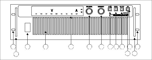
Front Panel
Front Panel
1 |
3 |
4 |
5 |
6 |
7 |
8 |
9 |
10 |
11 |
1 |
2 |
|
|
|
|
|
|
|
|
12 |
2 |
Figure 1.1 |
Front Panel |
|
|
|
|
|
|
|
|
|
1.Rack mount brackets
2.Handles
3.On/Off switch
4.Air intake vents
5.Front panel display. See Figure 1.2, on page 19 for details.
6.Voltage knob: Turn knob to increase or decrease output voltage.
7.Current knob: Turn knob to increase or decrease output current limit.
8.OUT ON/OFF button: Toggle between Output ON and Output OFF.
9.LCL/RMT button: Toggle between local mode and remote mode.
10.SET POINT button: View and set operating setpoints for output voltage and current (Local Mode only).
11.OVP button: View and set Over Voltage Protection setpoint with OVP Adjust Potentiometer.
12.OVP SET: Front panel screw, Over Voltage Protection Adjust Potentiometer.
18 |
Operating Manual for XPR Series Power Supply |
About The XPR Power Supply
Status Annunciators
Status Annunciators
|
|
|
|
|
11 |
|
|
|
|
|
10 |
|
1 |
2 |
4 |
6 |
8 |
|
3 |
5 |
7 |
9 |
|
Figure 1.2 |
Front Panel Display, Status Annunciators |
|
|
||
1.AC: The AC input is out of range and has caused the output of the supply to be shut down (red)
2.OTP: The internal Over Temperature Protection threshold has been exceeded, disabling the supply output until the sensors cool to within the normal operating temperature range (red)
3.INT: The external shutdown line has been asserted, disabling the output of the supply (green)
4.OVP: The output Over Voltage Protection threshold have been exceeded, latching the supply output off (red)
5.SNS: The remote sense line protection circuit has been activated, latching the supply output off (red)
6.ON: The supply output is enabled (green)
7.OFF: The supply output has been disabled (green)
8.LCL: The supply is in Local control mode (green)
9.RMT: The supply is in Remote program mode (green)
10.CV: The supply is operating in Constant Voltage mode (green)
11.CC: The supply is operating in Constant Current mode (green)
Release 1.1 |
19 |

About The XPR Power Supply
Rear Panel Connectors and Switch
Rear Panel Connectors and Switch
2 |
|
|
|
|
5 |
|
|
1 |
3 |
1 |
1 |
4 |
8 |
6 |
7 |
Figure 1.3 |
Rear panel |
|
|
|
|
|
|
1.Fan Exhaust Vents: Do Not Obstruct.
2.Remote Sensing Ports: From the rear panel point of view, left is negative; right is positive.
3.DC Output: Bus bars are shown. Terminal blocks are used for higher voltages (150 Vdc and higher).
4.Programming, Monitoring and User Line Connector (J1).
5.Programming, Monitoring and Shutdown Select Switch (S1).
6.Protective Conductor Ground Screw.
7.Ac Input.
8.Chassis ground stud.
Rear Panel S1 The S1 Programming, Monitoring, and Interlock select switch is an 8-position piano Switch DIP switch located on the power supply’s rear panel. See Figure 1.4. The S1 switch
enables you to choose:
•Resistive programming of output voltage or current limit
•Output voltage and current limit programming scales
•Output voltage and current monitor scales
•Remote shutdown circuit logic
•Over temperature shutdown mode
20 |
Operating Manual for XPR Series Power Supply |

About The XPR Power Supply
Rear Panel Connectors and Switch
1 Resistive Programming of Output Voltage
2 Resistive Programming of Output Current Limit
3 Selects Output Voltage Programming and Monitor Range select
4 Selects Output Current Limit Programming and Monitor Range select 5 Selects Output Voltage Control: Local or Remote
6 Selects Output Current Control: Local or Remote
7 Selects Remote Interlock Logic
8 Selects Over Temperature Shutdown Reset Mode
Figure 1.4 Programming and Monitoring S1 Switch
(Switch is shown in factory default configuration.)
The rear panel at the switch is labeled with OFF at the top and ON at the bottom. Any of the eight switches on S1 is OFF when it has been flipped up to break contact, ON when flipped down to close contact.
Table 1.1 shows the functions assigned to each S1 switch. Factory defaults are underlined.
Table 1.1 Rear Panel S1 Switch Assignments
Switch |
Function |
OFF |
ON |
S1-1 |
1 mA current source for resistive programming of |
Voltage source |
Resistive programming |
|
output voltage |
programming |
(0-5 k, 0-10 k) |
S1-2 |
1 mA current source for resistive programming of |
Voltage source |
Resistive programming |
|
output current limit |
programming |
(0-5 k, 0-10 k) |
S1-3 |
Output voltage programming and monitor range |
0-5 V (0-5 k) |
0-10 V (0-10 k) |
|
select |
|
|
|
|
|
|
S1-4 |
Output current limit programming and monitor |
0-5 V (0-5 k) |
0-10 V (0-10 k) |
|
range select |
|
|
S1-5 |
Output voltage control mode select |
Local Control |
Remote Control |
|
|
|
|
S1-6 |
Output current control mode select |
Local Control |
Remote Control |
|
|
|
|
S1-7 |
Remote Interlock logic signal select |
Active High=OFF |
Active Low=OFF |
|
|
|
|
S1-8 |
Over temperature shutdown reset mode select |
Auto reset |
Latch OFF |
|
|
|
|
Resetting the Switches
Before making any changes to the switch settings, either turn off the AC power switch or disable the power supply output by pushing the front panel OUT ON/OFF switch to its IN position. This temporarily shuts down the power supply. The front panel OFF LED turns on. Then use any small, flat-bladed screwdriver to change the switch settings.
Release 1.1 |
21 |

About The XPR Power Supply
Rear Panel Connectors and Switch
Rear Panel J1 The J1 Programming and Monitoring connector is a 15-terminal wire clamp Connector connector located on the power supply’s rear panel. See Figure 1.5. The J1 connector
provides access to the following functions:
•Remote programming of output voltage AND/OR current limit
•Remote monitoring of calibrated readback signals for output voltage and output current
•Remote control of the shutdown function using TTL-compatible signals (Interlock module)
•15 V user supply to allow for contract closure control of the remote on/off line, current limited
1 Output Voltage Programming Input
2 Output Current Limit Programming Input
3 Program Return
4 Output Voltage Monitor
5 Output Current Monitor
6 Monitor Return
7N/C
8Ground Return
9 + 15 V User Signal
10 N/C
11 Interlock Return (–)
12 Interlock Signal (+)
13N/C
14Shutdown Return (–)
15Shutdown (+)
Figure 1.5 Programming and Monitoring J1 Connector
See Table 1.2, on page 23 for the list of the J1 connector terminal numbers, their references, and corresponding functions.
22 |
Operating Manual for XPR Series Power Supply |
Loading...