


PV100S-208
PV100S-480
Planning and Installation Manual
PV100S 100 kW
Grid-Tied
Photovoltaic
Inverter

PV100S 100 kW Grid-Tied
Photovoltaic Inverter
Planning and Installation Manual
About Xantrex
Xantrex Technology Inc. is a world-leading supplier of advanced power electronics and controls with products from 50 watt mobile units to 1.5 MW utility-scale systems for wind, solar, batteries, fuel cells, microturbines, and backup power applications in both grid-connected and stand-alone systems. Xantrex products include inverters, battery chargers, programmable power supplies, and variable speed drives that convert, supply, control, clean, and distribute electrical power.
Trademarks
PV100S 100 kW Grid-Tied Photovoltaic Inverter is a trademark of Xantrex International. Xantrex is a registered trademark of Xantrex International.
Other trademarks, registered trademarks, and product names are the property of their respective owners and are used herein for identification purposes only.
Notice of Copyright
PV100S 100 kW Grid-Tied Photovoltaic Inverter Planning and Installation Manual© May 2005 Xantrex International. All rights reserved.
Disclaimer
UNLESS SPECIFICALLY AGREED TO IN WRITING, XANTREX TECHNOLOGY INC. (“XANTREX”)
(a)MAKES NO WARRANTY AS TO THE ACCURACY, SUFFICIENCY OR SUITABILITY OF ANY TECHNICAL OR OTHER INFORMATION PROVIDED IN ITS MANUALS OR OTHER DOCUMENTATION.
(b)ASSUMES NO RESPONSIBILITY OR LIABILITY FOR LOSS OR DAMAGE, WHETHER DIRECT, INDIRECT, CONSEQUENTIAL OR INCIDENTAL, WHICH MIGHT ARISE OUT OF THE USE OF SUCH INFORMATION. THE USE OF ANY SUCH INFORMATION WILL BE ENTIRELY AT THE USER’S RISK.
Date and Revision
May 2005 Revision C
Part Number
152315 Rev C
Contact Information
Telephone: |
1 800 670 0707 |
(toll free North America) |
|
1 360 925 5097 |
(direct) |
Fax: |
1 360 925 5143 |
(direct) |
Email: |
customerservice@xantrex.com |
|
Web: |
www.xantrex.com |
|

About This Manual
Purpose
The purpose of this Planning and Installation Manual is to provide explanations and procedures for planning and installing the PV100S 100 kW Grid-Tied Photovoltaic Inverter.
Scope
The Manual provides safety guidelines, detailed planning and setup information, and procedures for installing the inverter.
Audience
The Manual is intended for use by anyone who plans to construct or install a system involving the PV100S 100 kW Grid-Tied Photovoltaic Inverter. Installers must meet all local and state code requirements for licensing and training for the installation of Electrical Power Systems with AC and DC voltage to 600 volts.
Organization
This Manual is organized into four chapters:
Chapter 1, “Introduction” provides information about the features and functions of the PV100S 100 kW Grid-Tied Photovoltaic Inverter.
Chapter 2, “Planning” provides information to help plan the installation of the PV100S 100 kW Grid-Tied Photovoltaic Inverter.
Chapter 3, “Installation” describes the procedures needed to install the PV100S 100 kW Grid-Tied Photovoltaic Inverter. This section includes unpacking and moving instructions, mounting instructions, and cabling instructions.
Chapter 4, “Verification” provides a checklist to ensure the installation of the PV100S is correct and complete.
152315 Rev C |
iii |

About This Manual
Conventions Used
The following conventions are used in this guide.
WARNING
Warnings identify conditions or practices that could result in personal injury or loss of life.
CAUTION
Cautions identify conditions or practices that could result in damage to the unit or other equipment.
Important: These notes describe things which are important for you to know, but not as serious as a caution or warning.
This Manual contains information for two models of the PV100S 100 kW GridTied Photovoltaic Inverter. One model is designed to operate with a 208 Vac utility input, and the other model is designed to operate with a 480 Vac utility input.
•The model PV100S-208 100kW Grid-Tied Photovoltaic Inverter
(208 Vac input) will be referred to as the PV100S-208 when it is being referenced individually.
•The model PV100S-480 100kW Grid-Tied Photovoltaic Inverter
(480 Vac input) will be referred to as the PV100S-480 when it is being referenced individually.
•When the both models are being referenced together, they will be referred to as the PV100S.
iv |
152315 Rev C |

About This Manual
Abbreviations and Acronyms
ANSI |
American National Standards Institute |
CCU2 |
Converter Control Unit 2 |
CFM |
Cubic Feet per Minute |
CW |
Clockwise |
DSP |
Digital Signal Processor |
FPGA |
Field Programmable Gate Array |
GUI |
Graphical User Interface |
IEEE |
Institute of Electrical and Electronics Engineers |
IGBT |
Insulated Gate Bipolar Transistor |
IPM |
Intelligent Power Module |
kcmil |
1000 circular mils |
LAN |
Local Area Network |
LCD |
Liquid Crystal Display |
NFPA |
National Fire Protection Association |
PBX |
Private Branch Exchange |
PSL |
Phase-Shift Loop |
POTS |
Plain Old Telephone Service |
PV |
Photovoltaic |
UFCU |
Universal Frontpanel Control Unit |
Related Information
You can find more information about Xantrex Technology Inc. as well as its products and services at www.xantrex.com.
152315 Rev C |
v |
vi
Important Safety Instructions
SAVE THESE INSTRUCTIONS - DO NOT DISCARD
This manual contains important safety instructions for the PV100S that shall be followed during installation and maintenance procedures.
WARNING: Shock Hazard
Read and keep this Planning and Installation Manual for future reference. Before installing PV100S (either model), read all instructions, cautionary markings, and all other appropriate sections of this manual. Failure to adhere to these warnings could result in severe shock or possible death. Exercise extreme caution at all times to prevent accidents.
WARNING: Shock Hazard
The PV100S enclosures contain exposed high-voltage conductors. The enclosure doors should remain closed with the latches tightened, except during installation, maintenance or testing. These servicing instructions are for use by qualified personnel who meet all local and state code requirements for licensing and training for the installation of Electrical Power Systems with AC and DC voltage to 600 volts. To reduce the risk of electric shock, do not perform any servicing other than that specified in the installation instructions unless you are qualified to do so. Do not open the cabinet doors if extreme moisture is present (rain or heavy dew).
WARNING: Lethal Voltage
In order to remove all sources of voltage from the PV100S, the incoming power must be de-energized at the source. This may be done at the main utility circuit breaker and by opening the AC Disconnect and the DC Disconnect Switches on the PV100S. Review the system configuration to determine all of the possible sources of energy. In addition, allow 5 minutes for the DC bus capacitors, located on the ceiling of the cabinet, to discharge after removing power.
152315 Rev C |
vii |

Safety
General Safety Precautions
1.When installing the PV100S use only components recommended or sold by Xantrex. Doing otherwise may result in a risk of fire, electric shock, injury to persons, and will void the warranty.
2.Do not attempt to operate the PV100S if it has been dropped, or received more than cosmetic damage during transport or shipping. If the PV100S is damaged, or suspected to be damaged, see the Warranty for this unit in the PV100S 100 kW Grid-Tied Photovoltaic Inverter Operation and Maintenance Manual.
3.To reduce the risk of electrical shock, lock-out and tag the PV100S before attempting any maintenance, service, or cleaning.
Personal Safety
Follow these instructions to ensure your safety while working with the PV100S.
Safety Equipment
Authorized service personnel must be equipped with standard safety equipment including the following:
•Safety glasses
•Ear protection
•Steel-toed safety boots
•Safety hard hats
•Padlocks and tags
•Appropriate meter to verify that the circuits are de-energized (600 Vac and DC rated, minimum)
Check local safety regulations for other requirements.
Wiring Requirements
1.All wiring methods and materials shall be in accordance with the National Electrical Code ANSI/NFPA 70. When sizing conductors and conduits interfacing to the PV100S, both shall be in accordance with the National Electric Code ANSI/NFPA 70, as well as all state and local code requirements.
2.Use copper conductors only with insulation rated for 90 °C.
3. The PV100S has a three-phase output. It is marked with this symbol:
4.The AC power conductor wiring interfacing with the AC terminals in the Transformer Enclosure are located at T6-X1, T6-X2, and T6-X3. These terminals should be tightened to a torque value of 420 in-lbs (47.5 Nm) for model PV100S-208 and model PV100S-480. Conductors terminated to these
viii |
152315 Rev C |
Safety
terminals must use a crimp-on type ring terminal or compression-type lug. The terminals are one bolt per pole. See Figure 3-14 on page 3–15 for the location of these terminals.
5.The AC power conductor wiring interfacing with the AC terminals in the Main Inverter Enclosure are located at TB4-A, TB4-B, and TB4- C. These terminals are to be tightened to a torque value of 275 in-lbs (31.1 Nm) for model PV100S-208 and model PV100S-480. The terminals will accept a conductor size of 350 kcmil. See Figure 3-15 on page 3–16 for the location of these terminals.
6.The AC power conductor wiring interfacing with the AC terminals in the AC Interface Enclosure are located at S1-2T1, S1-4T2, and S1-6T3. These terminals should be tightened to a torque value of 310 in-lbs (35.0 Nm) for model PV100S-208 and to a torque value of 115 in-lbs (13.0 Nm) for model PV100S-480. See Figure 3-16 on page 3–16 for the location of these terminals and the cautionary note on page 3–17.
7.The AC neutral conductor from the utility is terminated in the AC Interface Enclosure at the TB6-Neutral terminal. This terminal requires the use of a crimp-on type ring terminal or compression-type lug and should be tightened to a torque value of 228 in-lbs (25.7 Nm) for model PV100S-208 and model PV100S-480. See Figure 3-18 on page 3–18 for the location of these terminals.
8.The DC power conductor wiring interfacing with the DC terminals at TB3-1, TB3-2, and TB3-3 are to be tightened to a torque value of 500 in-lbs
(56.5 Nm) for model PV100S-208 and model PV100S-480. These terminals will accept a conductor size of 500 kcmil. Keep these cables together as much as possible and ensure that all cables pass through the same knockout and conduit fittings, thus allowing any inductive currents to cancel. See Figure 3- 19 on page 3–19 for the location of these terminals.
9.This product is intended to be installed as part of a permanently grounded electrical system per the National Electric Code ANSI/NFPA 70. A copper ground rod must be installed within three feet of the PV100S enclosure. This is the single point earth ground for the inverter system. The single point ground for the system is to be made at the AC ground bus bar (TB2) in the AC Interface Enclosure. This terminal requires the use of a crimp on type ring terminal or compression-type lug and should be tightened to a torque value of 420 in-lbs (47.5 Nm) for model PV100S-208 and model PV100S-480.
10.The equipment grounds on the PV100S are marked with this symbol: 
11.AC overcurrent protection for the utility interconnect (Grid-tie) must be provided by the installers as part of the PV100S installation.
CAUTION: Fire Hazard
In accordance with the National Electrical Code, ANSI/NFPA 70, connect only to a circuit provided with 400 amperes maximum branch circuit overcurrent protection for model PV100S-208 and only to a circuit provided with 200 amperes maximum branch circuit overcurrent protection for model PV100S-480.
152315 Rev C |
ix |
Safety
Operational Safety Procedures
Never work alone when servicing this equipment. A team of two is required until the equipment is properly de-energized, locked-out and tagged, and verified deenergized with a meter.
Thoroughly inspect the equipment prior to energizing. Verify that no tools or equipment have inadvertently been left behind.
Lockout and Tag
Safety requirements mandate that this equipment not be serviced while energized. Power sources for the PV100S must be locked-out and tagged prior to servicing.
A padlock and tag should be installed on each energy source prior to servicing.
WARNING: Shock Hazard
Review the system schematic for the installation to verify that all available energy sources are de-energized. DC bus voltage may also be present. Be sure to wait the full 5 minutes to allow the capacitors to discharge completely.
The PV100S can be energized from both the AC source and the DC source. To ensure that the inverter is de-energized prior to servicing, lockout and tag the PV100S using the following procedure.
1.Open, lockout, and tag the incoming power at the utility main circuit breaker.
2.Open, lockout, and tag the AC Disconnect Switch (S1) on the AC Interface Enclosure. See Figure 1-4 on page 1–9 for the location of the AC Disconnect Switch.
3.Open, lockout, and tag the DC Disconnect Switch (S2) on the DC Interface Enclosure. See Figure 1-4 on page 1–9 for the location of the DC Disconnect Switch.
4.Using a confirmed, accurate meter, verify all power to the inverter is deenergized. A confirmed, accurate meter must be verified on a known voltage before use. Ensure that all incoming energy sources are de-energized by checking the following locations.
a)Inverter Terminals: TB4-A, TB4-B, TB4-C (Phase A, B, C) See Figure 3-15 on page 3–16.
b)Utility Terminals: Bottom of S1-2T1, S1-4T2, S1-6T3
See Figure 3-16 on page 3–16.
c)PV Terminals: Bottom of TB3-1, TB3-2, TB3-3 (PV+, PV-, GND)
See Figure 3-19 on page 3–19.
x |
152315 Rev C |

Safety
De-Energize/Isolation Procedure
The following procedure should be followed to de-energize the PV100S for maintenance.
WARNING
The terminals of the DC input may be energized if the PV arrays are energized. In addition, allow 5 minutes for all capacitors within the main enclosure to discharge after disconnecting the PV100S from AC and DC sources.
To isolate the PV100S:
1.Turn the ON/OFF switch to the OFF position.
2.Open the DC interface disconnect switch.
3.Open the AC interface disconnect switch.
4.Open the utility connection circuit breaker.
5.Install lockout devices on the utility connection circuit breaker and DC disconnect switch.
Interconnection Standards Compliance
The PV100S has been tested and listed by Underwriters Laboratories to be in compliance with UL1741 Static Inverters And Charge Controllers For Use In Photovoltaic Power Systems, as well as IEEE-929-2000 Recommended Practice For Utility Interface of Photovoltaic (PV) Systems.
IEEE-929-2000 provides guidance regarding equipment and functions necessary to ensure compatible operation of photovoltaic systems which are connected in parallel with the electric utility.
UL1741 is the standard applied by Underwriters Laboratory to the PV100S to verify it meets the recommendations of IEEE-929-2000.
Refer to both documents for details of these recommendations and test procedures.
152315 Rev C |
xi |
xii

Contents
Important Safety Instructions - - - - - - - - - - - - - - - - - - - - - - - - - - - - - - - - - - - - - - - - - - -vii
1 Introduction
Description of the PV100S - - - - - - - - - - - - - - - - - - - - - - - - - - - - - - - - - - - - - - - - - - - - - - - - 1–2
System Specifications - - - - - - - - - - - - - - - - - - - - - - - - - - - - - - - - - - - - - - - - - - - - - - - - - - - 1–4
Electrical Specifications - - - - - - - - - - - - - - - - - - - - - - - - - - - - - - - - - - - - - - - - - - - - - - - 1–4
Over Voltage, Under Voltage and Frequency Ranges - - - - - - - - - - - - - - - - - - - - - - - - - 1–4
System Ground Requirements - - - - - - - - - - - - - - - - - - - - - - - - - - - - - - - - - - - - - - - - 1–5
System Neutral Requirements - - - - - - - - - - - - - - - - - - - - - - - - - - - - - - - - - - - - - - - - - 1–5
Utility Side Isolation Transformer Requirements - - - - - - - - - - - - - - - - - - - - - - - - - - - - 1–5
Environmental Specifications - - - - - - - - - - - - - - - - - - - - - - - - - - - - - - - - - - - - - - - - - - - - 1–6
Operator Interface Controls- - - - - - - - - - - - - - - - - - - - - - - - - - - - - - - - - - - - - - - - - - - - - - - - 1–7
Main Enclosure Door Interlock Switch - - - - - - - - - - - - - - - - - - - - - - - - - - - - - - - - - - - - - 1–7
On/Off Switch - - - - - - - - - - - - - - - - - - - - - - - - - - - - - - - - - - - - - - - - - - - - - - - - - - - - - - 1–8
AC and DC Disconnect Switches - - - - - - - - - - - - - - - - - - - - - - - - - - - - - - - - - - - - - - - - - 1–9
Communication Features - - - - - - - - - - - - - - - - - - - - - - - - - - - - - - - - - - - - - - - - - - - - - - - - - 1–9
System Status and Fault Reporting - - - - - - - - - - - - - - - - - - - - - - - - - - - - - - - - - - - - - - - 1–10
Data Logging - - - - - - - - - - - - - - - - - - - - - - - - - - - - - - - - - - - - - - - - - - - - - - - - - - - - - 1–10
Communication Methods - - - - - - - - - - - - - - - - - - - - - - - - - - - - - - - - - - - - - - - - - - - - - - - - 1–11
Universal Front Panel Control Unit (UFCU) - - - - - - - - - - - - - - - - - - - - - - - - - - - - - - - - - 1–11
PC Connection Methods - - - - - - - - - - - - - - - - - - - - - - - - - - - - - - - - - - - - - - - - - - - - - - 1–12
POTS Access - - - - - - - - - - - - - - - - - - - - - - - - - - - - - - - - - - - - - - - - - - - - - - - - - - - 1–13
Wireless Access - - - - - - - - - - - - - - - - - - - - - - - - - - - - - - - - - - - - - - - - - - - - - - - - - 1–13
Ethernet LAN Access - - - - - - - - - - - - - - - - - - - - - - - - - - - - - - - - - - - - - - - - - - - - - 1–14
Direct Access - - - - - - - - - - - - - - - - - - - - - - - - - - - - - - - - - - - - - - - - - - - - - - - - - - - 1–14
2 Planning
Overview of PV100S Installation - - - - - - - - - - - - - - - - - - - - - - - - - - - - - - - - - - - - - - - - - - - - 2–2
PV Planning - - - - - - - - - - - - - - - - - - - - - - - - - - - - - - - - - - - - - - - - - - - - - - - - - - - - - - - - - - 2–3
Ventilation and Serviceability Requirements - - - - - - - - - - - - - - - - - - - - - - - - - - - - - - - - - - - - 2–3
Ground Requirements - - - - - - - - - - - - - - - - - - - - - - - - - - - - - - - - - - - - - - - - - - - - - - - - - - - 2–4
System Neutral Requirements - - - - - - - - - - - - - - - - - - - - - - - - - - - - - - - - - - - - - - - - - - - - - - 2–4
Communication Requirements- - - - - - - - - - - - - - - - - - - - - - - - - - - - - - - - - - - - - - - - - - - - - - 2–4
Utility Side Isolation Transformer Requirements - - - - - - - - - - - - - - - - - - - - - - - - - - - - - - - - - 2–4
Electrical Diagrams and Schematics - - - - - - - - - - - - - - - - - - - - - - - - - - - - - - - - - - - - - - - - - - 2–5
Layout Options - - - - - - - - - - - - - - - - - - - - - - - - - - - - - - - - - - - - - - - - - - - - - - - - - - - - - - - - 2–6
Conduit Penetration - - - - - - - - - - - - - - - - - - - - - - - - - - - - - - - - - - - - - - - - - - - - - - - - - - - - - 2–8
Conductor and Conduit Sizing - - - - - - - - - - - - - - - - - - - - - - - - - - - - - - - - - - - - - - - - - - - - - 2–11
Anchoring the PV100S- - - - - - - - - - - - - - - - - - - - - - - - - - - - - - - - - - - - - - - - - - - - - - - - - - 2–13
152315 Rev C |
xiii |

Contents
3 Installation
Equipment Required - - - - - - - - - - - - - - - - - - - - - - - - - - - - - - - - - - - - - - - - - - - - - - - - - - - - 3–2 Unloading - - - - - - - - - - - - - - - - - - - - - - - - - - - - - - - - - - - - - - - - - - - - - - - - - - - - - - - - - - - 3–2 Moving the PV100S - - - - - - - - - - - - - - - - - - - - - - - - - - - - - - - - - - - - - - - - - - - - - - - - - 3–3 Unpacking the PV100S - - - - - - - - - - - - - - - - - - - - - - - - - - - - - - - - - - - - - - - - - - - - - - - 3–3 Removing the Pallet and Moving the PV100S - - - - - - - - - - - - - - - - - - - - - - - - - - - - - - - - 3–4 Mounting and Anchoring the Units - - - - - - - - - - - - - - - - - - - - - - - - - - - - - - - - - - - - - - - - - - 3–5 Opening or Closing Access Doors- - - - - - - - - - - - - - - - - - - - - - - - - - - - - - - - - - - - - - - - - - - 3–6 Conduit Installation - - - - - - - - - - - - - - - - - - - - - - - - - - - - - - - - - - - - - - - - - - - - - - - - - - - - 3–9 Wiring - General - - - - - - - - - - - - - - - - - - - - - - - - - - - - - - - - - - - - - - - - - - - - - - - - - - - - - -3–10 Overcurrent Protection - - - - - - - - - - - - - - - - - - - - - - - - - - - - - - - - - - - - - - - - - - - - - - - -3–11 Conductor Termination - - - - - - - - - - - - - - - - - - - - - - - - - - - - - - - - - - - - - - - - - - - - - - -3–11 Wire Gauge and Torque Requirements - - - - - - - - - - - - - - - - - - - - - - - - - - - - - - - - - - - - -3–12 Grounding - - - - - - - - - - - - - - - - - - - - - - - - - - - - - - - - - - - - - - - - - - - - - - - - - - - - - - - -3–12 System Neutral Requirements - - - - - - - - - - - - - - - - - - - - - - - - - - - - - - - - - - - - - - - - - - -3–13 Utility Side Isolation Transformer Requirements - - - - - - - - - - - - - - - - - - - - - - - - - - - - - -3–13 Wiring - Specific - - - - - - - - - - - - - - - - - - - - - - - - - - - - - - - - - - - - - - - - - - - - - - - - - - - - - -3–14 AC Connections - - - - - - - - - - - - - - - - - - - - - - - - - - - - - - - - - - - - - - - - - - - - - - - - - - - -3–14 PV Array Connections - - - - - - - - - - - - - - - - - - - - - - - - - - - - - - - - - - - - - - - - - - - - - - - -3–19 PC Communications - - - - - - - - - - - - - - - - - - - - - - - - - - - - - - - - - - - - - - - - - - - - - - - - - - - -3–20 PC Connection Methods - - - - - - - - - - - - - - - - - - - - - - - - - - - - - - - - - - - - - - - - - - - - - - -3–20 Establishing a POTS Connection - - - - - - - - - - - - - - - - - - - - - - - - - - - - - - - - - - - - - -3–21 Establishing Wireless Connection - - - - - - - - - - - - - - - - - - - - - - - - - - - - - - - - - - - - -3–22 Establishing an Ethernet LAN Connection - - - - - - - - - - - - - - - - - - - - - - - - - - - - - - - -3–22 Direct Connection - - - - - - - - - - - - - - - - - - - - - - - - - - - - - - - - - - - - - - - - - - - - - - - -3–23
4 Verification
Verification Procedure Summary - - - - - - - - - - - - - - - - - - - - - - - - - - - - - - - - - - - - - - - - - - - 4–2
Visual Inspection of Mechanical Connections - - - - - - - - - - - - - - - - - - - - - - - - - - - - - - - - - - - 4–3
Visual Inspection of Electrical Connections - - - - - - - - - - - - - - - - - - - - - - - - - - - - - - - - - - - - 4–3
Visual Inspection, Isolation Transformer Wye/Wye - - - - - - - - - - - - - - - - - - - - - - - - - - - - - - - 4–4
Corrective Action - - - - - - - - - - - - - - - - - - - - - - - - - - - - - - - - - - - - - - - - - - - - - - - - - - - - - - 4–4
A Schematics |
|
Index - - - - - - - - - - - - - - - - - - - - - - - - - - - - - - - - - - - - - - - - - - - - - - - - - - - - - - - - - - - - - - - |
IX–1 |
xiv |
152315 Rev C |

Tables
Table 1-1 Electrical Specifications - - - - - - - - - - - - - - - - - - - - - - - - - - - - - - - - - - - - - - - - - - - - 1–4 Table 1-2 Over/Under Voltage and Over/Under Frequency Ranges - - - - - - - - - - - - - - - - - - - - - - 1–4 Table 1-3 Environmental Specifications - - - - - - - - - - - - - - - - - - - - - - - - - - - - - - - - - - - - - - - - 1–6 Table 3-1 AC Terminal Wire Gauge, Bolt Size, and Torque Values - - - - - - - - - - - - - - - - - - - - 3–12 Table 3-2 DC Terminal Wire Gauge, Bolt Size, and Torque Values - - - - - - - - - - - - - - - - - - - - 3–12
152315 Rev C |
xv |
xvi

Figures
Figure 1-1 Dimensions (Not to scale) - - - - - - - - - - - - - - - - - - - - - - - - - - - - - - - - - - - - - - - - - - 1–3 Figure 1-2 PV100S Operator Interface Components- - - - - - - - - - - - - - - - - - - - - - - - - - - - - - - - - 1–7 Figure 1-3 On/Off Switch - - - - - - - - - - - - - - - - - - - - - - - - - - - - - - - - - - - - - - - - - - - - - - - - - - 1–8 Figure 1-4 AC and DC Disconnect Switches- - - - - - - - - - - - - - - - - - - - - - - - - - - - - - - - - - - - - - 1–9 Figure 1-5 LCD Display and UFCU Location - - - - - - - - - - - - - - - - - - - - - - - - - - - - - - - - - - - - 1–11 Figure 1-6 PC Connections in the Communications Enclosure- - - - - - - - - - - - - - - - - - - - - - - - - 1–12 Figure 1-7 POTS Access - - - - - - - - - - - - - - - - - - - - - - - - - - - - - - - - - - - - - - - - - - - - - - - - - - 1–13 Figure 1-8 Wireless Access - - - - - - - - - - - - - - - - - - - - - - - - - - - - - - - - - - - - - - - - - - - - - - - - 1–13 Figure 1-9 Ethernet LAN Access - - - - - - - - - - - - - - - - - - - - - - - - - - - - - - - - - - - - - - - - - - - - 1–14 Figure 1-10 Direct Access - - - - - - - - - - - - - - - - - - - - - - - - - - - - - - - - - - - - - - - - - - - - - - - - - - 1–14 Figure 2-1 PV100S Layout Option A- - - - - - - - - - - - - - - - - - - - - - - - - - - - - - - - - - - - - - - - - - - 2–6 Figure 2-2 PV100S Layout Option B- - - - - - - - - - - - - - - - - - - - - - - - - - - - - - - - - - - - - - - - - - - 2–7 Figure 2-3 Conduit Entry Figure Reference - - - - - - - - - - - - - - - - - - - - - - - - - - - - - - - - - - - - - - 2–8 Figure 2-4 Inductor Enclosure Conduit Entry, Left Side - - - - - - - - - - - - - - - - - - - - - - - - - - - - - - 2–9 Figure 2-5 Transformer Enclosure Conduit Entry, Right Side - - - - - - - - - - - - - - - - - - - - - - - - - - 2–9 Figure 2-6 AC Interface Enclosure Conduit Entry, Left Side - - - - - - - - - - - - - - - - - - - - - - - - - - 2–10 Figure 2-7 DC Interface Enclosure, Bottom Side - - - - - - - - - - - - - - - - - - - - - - - - - - - - - - - - - - 2–10 Figure 2-8 Communications Enclosure Conduit Entry, Bottom Side - - - - - - - - - - - - - - - - - - - - - 2–10 Figure 2-9 Main Inverter Anchor Bolt Pattern (Not to scale) - - - - - - - - - - - - - - - - - - - - - - - - - - 2–13 Figure 2-10 AC Interface/Transformer Anchor Bolt Pattern (Not to Scale) - - - - - - - - - - - - - - - - - 2–14 Figure 3-1 Moving the crated PV100S - - - - - - - - - - - - - - - - - - - - - - - - - - - - - - - - - - - - - - - - - - 3–3 Figure 3-2 Forklift Lifting Locations - Underneath Unit - - - - - - - - - - - - - - - - - - - - - - - - - - - - - - 3–4 Figure 3-3 Mounting Hole Locations - - - - - - - - - - - - - - - - - - - - - - - - - - - - - - - - - - - - - - - - - - - 3–5 Figure 3-4 Inverter Enclosure Access Doors - - - - - - - - - - - - - - - - - - - - - - - - - - - - - - - - - - - - - - 3–6 Figure 3-5 AC Interface Access Door - - - - - - - - - - - - - - - - - - - - - - - - - - - - - - - - - - - - - - - - - - 3–7 Figure 3-6 DC Interface Access Door - - - - - - - - - - - - - - - - - - - - - - - - - - - - - - - - - - - - - - - - - - 3–7 Figure 3-7 Transformer Access Panels- - - - - - - - - - - - - - - - - - - - - - - - - - - - - - - - - - - - - - - - - - 3–8 Figure 3-8 Inductor Access Panels - - - - - - - - - - - - - - - - - - - - - - - - - - - - - - - - - - - - - - - - - - - - 3–8 Figure 3-9 Conduit Installation - - - - - - - - - - - - - - - - - - - - - - - - - - - - - - - - - - - - - - - - - - - - - - - 3–9 Figure 3-10 Single-point Ground (TB2) Ground Bar - - - - - - - - - - - - - - - - - - - - - - - - - - - - - - - - 3–12 Figure 3-11 Chassis Ground Bar (TB1) - - - - - - - - - - - - - - - - - - - - - - - - - - - - - - - - - - - - - - - - - 3–13 Figure 3-12 Route AC Cables through the Conduit - - - - - - - - - - - - - - - - - - - - - - - - - - - - - - - - - 3–14 Figure 3-13 Tie-wraps on the AC Sense Harness- - - - - - - - - - - - - - - - - - - - - - - - - - - - - - - - - - - 3–15 Figure 3-14 AC Terminal Connections in the AC Interface/Transformer Enclosure - - - - - - - - - - - 3–15 Figure 3-15 AC Terminal Connections in the Main Inverter Enclosure - - - - - - - - - - - - - - - - - - - - 3–16 Figure 3-16 AC Terminal Connections in the AC Interface Enclosure - - - - - - - - - - - - - - - - - - - - 3–16 Figure 3-17 Connecting the AC Sense Harness - - - - - - - - - - - - - - - - - - - - - - - - - - - - - - - - - - - - 3–17
152315 Rev C |
xvii |

Figures
Figure 3-18 AC Terminal Connections from the Utility- - - - - - - - - - - - - - - - - - - - - - - - - - - - - - -3–18 Figure 3-19 PV Array Cable Routing and Terminations - - - - - - - - - - - - - - - - - - - - - - - - - - - - - -3–19 Figure 3-20 Telephone Cable Routing - - - - - - - - - - - - - - - - - - - - - - - - - - - - - - - - - - - - - - - - - -3–21 Figure 3-21 RS232/FO Converter Kit Installation- - - - - - - - - - - - - - - - - - - - - - - - - - - - - - - - - - -3–23 Figure 3-22 Direct Connect Installation - - - - - - - - - - - - - - - - - - - - - - - - - - - - - - - - - - - - - - - - -3–24 Figure A-1 Electrical Diagram (sample)- - - - - - - - - - - - - - - - - - - - - - - - - - - - - - - - - - - - - - - - - A–3 Figure A-2 PV100S-480 Schematic for Main Power Distribution (152316 E1) - - - - - - - - - - - - - - A–4 Figure A-3 PV100S-480 Schematic for Control Power Distribution (152316 E2) - - - - - - - - - - - - - A–5 Figure A-4 PV100S-480 Schematic for Converter Control Unit (152316 E3)- - - - - - - - - - - - - - - - A–6 Figure A-5 PV100S-208 Schematic Main Power Distribution (152376 C1) - - - - - - - - - - - - - - - - - A–7 Figure A-6 PV100S-208 Schematic for Control Power Distribution (152376 C2) - - - - - - - - - - - - - A–8 Figure A-7 PV100S-208 Schematic for Converter Control Unit (152376 C3)- - - - - - - - - - - - - - - - A–9
xviii |
152315 Rev C |
1 Introduction
Chapter 1, “Introduction” provides information about the features and functions of the PV100S 100 kW Grid-Tied Photovoltaic Inverter.

Introduction
Description of the PV100S
The PV100S 100 kW Grid-Tied Photovoltaic Inverter is a UL 1741 listed, utility interactive, three-phase power conversion system for grid-connected photovoltaic arrays with a power rating of 100 kW. Designed to be easy to install and operate, the PV100S automates start-up, shutdown, and fault detection scenarios. With user-definable power tracking that matches the inverter to the array and adjustable delay periods, users are able to customize start up and shut down sequences. Multiple PV100S inverters are easily paralleled for larger power installations.
The PV100S power conversion system consists of a pulse-width modulated (PWM) inverter, switch gear for isolation and protection of the connected AC and DC power sources, and a custom Wye/Wye isolation transformer. Housed in a rugged NEMA 3R rated, powder-coated steel enclosure, the PV100S incorporates sophisticated Intellimod (IPM) Insulated Gate Bipolar Transistors (IGBTs) as the main power switching devices. An advanced, field-proven, Maximum Peak Power Tracker (MPPT) integrated within the PV100S control firmware ensures the optimum power throughput for harvesting energy from the photovoltaic array.
The advanced design of the PV100S includes an EMI output filter and the main AC contactor located electrically on the utility side of the isolation transformer. The location of the main AC contactor, and the ability to de-energize the isolation transformer during times of non-operation, greatly reduces the night-time tare losses consumed by an idle isolation transformer. An integrated soft-start circuit precludes nuisance utility-tie circuit breaker trips as the result of isolation transformer inrush current.
Additionally, the PV100S integrated controller contains self-protection features including over and under voltage and frequency safeguards. An integral anti-island protection scheme prevents the inverter from feeding power to the grid in the event of a utility outage. The PV100S includes a local user interface comprised of an ON/OFF switch, keypad, and 4-line, 80 character LCD display. A user-friendly, Graphic User Interface (GUI) provides a remote interface for operator interrogation of PV100S system status, control, metering/data logging and protective functions within the PV100S. The status, control, and logging features are also supported by the data modem (included) and can be accessed remotely.
The PV100S comes in two modules comprised of six enclosures to house the electronics described above. The first module includes the Main Inverter Enclosure, Inductor Enclosure, DC Interface Enclosure, and Communications Enclosure. The second module includes the Transformer Enclosure and AC Interface Enclosure. These components are identified in Figure 1-1 on page 1–3. Figure 1-1 also shows the dimensions and locations of the various enclosures that comprise the PV100S.
See “Layout Options” on page 2–6 for information on configuration options.
1–2 |
152315 Rev C |

Description of the PV100S
Front View |
|
60 ¼" |
|
(150.5 cm) |
|
|
|
Communications
Enclosure
49 7/8" |
|
(124.8 cm) |
DC Interface |
|
Enclosure |
59 ¼"
(148 cm)
AC |
|
Main |
|
|
Inverter |
|
|
Interface |
|
Enclosure |
|
Enclosure |
|
|
|
|
Transformer |
|
|
|
Enclosure |
Inductor |
29 ¼" |
44.0" |
|
||
|
Enclosure |
(73 cm) |
|
(110 cm) |
|
||
|
|
|
21 3/8"
 (53.5 cm)
Back |
Front |
Front |
Back |
|
83" |
||
|
|
|
(205.7 cm) |
DC Interface
Communications Enclosure
Enclosure
AC Interface
Enclosure 59 ¼"
(148 cm)
Inductor
Enclosure
33 ½" |
|
(83.75 cm) |
DC Side View |
AC Side View
Figure 1-1 Dimensions (Not to scale)
152315 Rev C |
1–3 |

Introduction
System Specifications
The PV100S has been designed for photovoltaic power systems, which operate within the following specifications.
CAUTION: Equipment Damage
Operation of the PV100S in a manner other than specified in this manual may cause damage to the PV100S and other system components and will void the terms of the warranty.
Electrical Specifications
Table 1-1 provides the AC and DC specifications for the PV100S.
Table 1-1 Electrical Specifications
Specification |
PV100S-208 |
PV100S-480 |
|
|
|
Nominal AC Input Voltage |
208 Vac |
480 Vac |
(+10% to -12% acceptable range) |
(183 to 228 Vac) |
(422 to 528 Vac) |
Maximum AC Output Current |
278 Arms |
121 Arms |
Nominal AC Input Frequency |
60 Hz |
60 Hz |
(+0.5 to -0.7 Hz acceptable range) |
(59.3 to 60.5 Hz) |
(59.3 to 60.5 Hz) |
Output Power |
100.0 kW |
100.0 kW |
Peak Power Tracking Window |
330 to 600 Vdc |
330 to 600 Vdc |
Maximum Open Circuit Voltage |
600 Vdc |
600 Vdc |
Maximum DC Input Current |
319 amps |
319 amps |
|
|
|
Over Voltage, Under Voltage and Frequency Ranges
Table 1-2 provides the over voltage, under voltage, over-frequency, and under-frequency detection limits for the PV100S. These detection limits have been factory tested and deemed to be in compliance with IEEE-929 and UL 1741 requirements for utility interaction.
Table 1-2 Over/Under Voltage and Over/Under Frequency Ranges
|
|
PV100S-208 |
|
PV100S-480 |
||
Vac Condition |
|
|
|
|
|
|
|
|
|
|
|
|
|
(% of Nominal) |
Voltage Range |
Trip Time |
Voltage Range |
Trip Time |
||
|
|
|
|
|
||
Vac < 50% |
Vac < 104 |
6 cycles |
Vac < 240 |
6 cycles |
||
50% < Vac < 88% |
104 |
< Vac < 183 |
2 seconds |
240 |
< Vac < 422 |
2 seconds |
88% < Vac < 110% |
183 |
< Vac < 228 |
normal operation |
422 |
< Vac < 528 |
normal operation |
110% < Vac < 137% |
228 |
< Vac < 285 |
2 seconds |
528 |
< Vac < 657 |
2 seconds |
137% < Vac |
285 |
< Vac |
2 cycles |
657 |
< Vac |
2 cycles |
f < rated -0.7 |
f < 59.3 |
6 cycles |
f < 59.3 |
6 cycles |
||
f > rated +0.5 |
f > 60.5 |
6 cycles |
f > 60.5 |
6 cycles |
||
1–4 |
152315 Rev C |
System Specifications
System Ground Requirements
This product is intended to be installed as part of a permanently grounded electrical system per the National Electric Code ANSI/NFPA 70. A copper ground rod must be installed within three feet of the PV100S enclosures and connected to the unit as described in “System Grounding” on page 3–12. The single-point ground for the system is to be made at the AC ground bus bar (TB2) in the AC Interface Enclosure.
System Neutral Requirements
The PV100S is designed to be installed as a 4-wire system. As required by the UL 1741 listing, a neutral conductor from the utility-interconnect must be terminated at TB6 within the AC Interface Enclosure to ensure that the AC voltage sensing circuit can perform an individual phase voltage (line-to-neutral) measurement. The function of the neutral connection is to provide a point of reference for measurement purposes that is essentially at ground potential. No power will flow through the neutral conductor.
Utility Side Isolation Transformer Requirements
The PV100S is supplied with a custom, high-efficiency, isolation transformer as part of the AC Interface/Transformer assembly. The utility side windings of the isolation transformer are configured Wye and must match the voltage at the utility inter-tie. The PV100S is a balanced, three-phase, current-sourcing inverter and only operates with the presence of a stable utility voltage. The transformer is also supplied with a neutral connection on the utility interconnect. Connection of this utility-side neutral does not affect the operation of the inverter, however connection of the neutral on the inverter-side does affect the operation and must be left floating or disconnected. Single-phase, grounded loads which may be present between the transformer and utility, will maintain their existing ground reference at the utility distribution transformer.
CAUTION: Equipment Damage
If the Isolation Transformer (T6-X0) neutral terminal is tied to ground, it will cause irreparable damage to the PV100S. Check local regulations for their requirements regarding the connection of the neutral.
WARNING: Lethal Voltage
Grounding the neutral of a Wye-wound transformer may create an “open delta” condition, depending on the utility configuration. This condition may keep the PV100S from detecting a loss of phase condition on the utility system, which may allow potentially lethal voltage to be present on the open-phase wiring.
152315 Rev C |
1–5 |

Introduction
Environmental Specifications
The following environmental specifications are the same for both models of the PV100S 100 kW Grid-Tied Photovoltaic Inverter.
Table 1-3 Environmental Specifications
Specification |
Value |
|
|
Dimensions |
|
Inverter and DC Interface |
82 in H x 60 1/4 in W x 22 in D |
|
(208 cm H x 153 cm W x 56 cm) |
Transformer and AC Interface |
44 in H x 50 in W x 34 in D |
|
(112 cm H x 127 cm W x 86 cm D) |
Overall System Footprint: |
12 ft W x 6 ft L (approximate) |
Layout Option A |
|
|
(3.6 m x 1.8 m) |
Layout Option B |
9 ft W x 7 ft L (approximate) |
|
(2.7 m W x 2.1 m L) |
|
|
Weight |
|
Inverter and DC Interface |
1000 lbs (approximate) |
Transformer and AC Interface |
1400 lbs (approximate) |
Overall Weight |
2400 lbs (approximate) |
|
|
Allowable Ambient Temperature |
|
Operating |
-20 °C to 50 °C Maximum |
Storage |
-40 °C to 50 °C Maximum |
|
|
Relative Humidity |
To 95%, Non-condensing |
Elevation |
Power Derated above 6600 ft |
|
|
Clearance (ventilation and |
In front of access doors: 36 in (91 cm) |
serviceability) |
In front of access panels: 36 in (91 cm) |
|
|
|
Sides: 12 in (30 cm) |
|
Back: 6 in (15 cm) |
|
|
Maximum Distance between Main |
15 ft (4.5 m) |
Inverter Enclosure and AC |
|
Interface/Transformer Enclosure |
|
|
|
1–6 |
152315 Rev C |
Operator Interface Controls
Operator Interface Controls
AC Disconnect
Switch
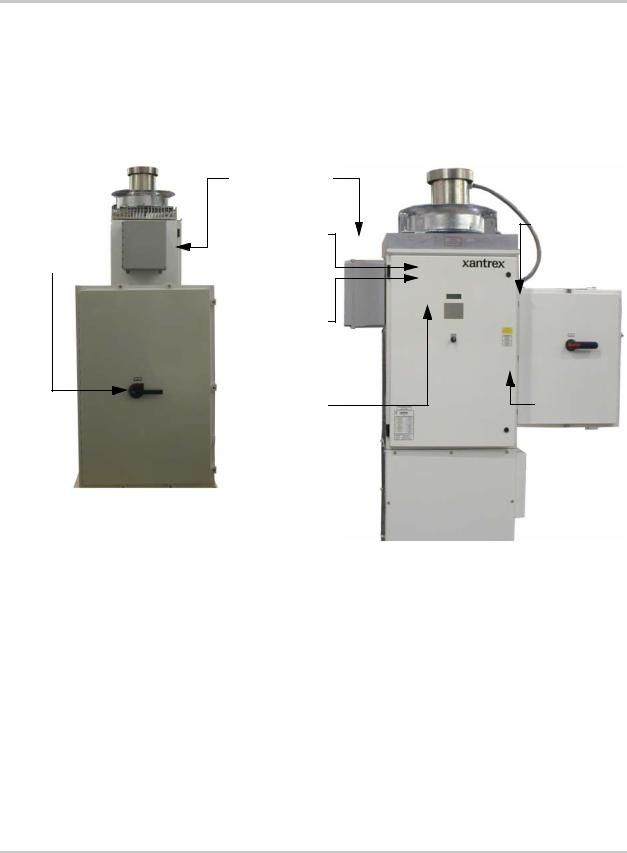
Operator interface controls are located on the front door of the main inverter enclosure. These controls include an ON/OFF Switch, 4-line LCD display and keypad called the Universal Frontpanel Control Unit (UFCU). Additionally there is an AC and DC Disconnect on the AC Interface Enclosure and the DC Interface Enclosure Doors.
Communication
Enclosure
DC Disconnect
LCD Switch
Display
Universal |
|
Frontpanel |
|
Control |
|
(UFCP) |
|
ON/OFF |
DC Interface |
Switch |
Enclosure |
AC Interface Enclosure |
Main Inverter Enclosure |
(AC Side View) |
(Front View) |
Figure 1-2 PV100S Operator Interface Components
Main Enclosure Door Interlock Switch
The front door of the PV100S main enclosure is equipped with an interlock switch to preclude operation while the front door is open. Opening the door of the main inverter enclosure will initiate an immediate controlled shutdown of the PV100S and opens both the main AC and DC contactors. The main AC and DC contactors cannot be closed unless the door’s interlock is in the engaged position. The PV100S is prevented from being restarted until the door is again closed and the switch is in the engaged position.
It is required that the PV100S main enclosure door must be locked during normal operation. The door interlock switch does NOT remove all hazardous voltages from inside the inverter. Before attempting to service the PV100S, follow the de-energize Lockout and Tag procedure on page x.
152315 Rev C |
1–7 |
 Loading...