


TM
3000W |
SINEWAVE |
|
|
|
INVEFREEDOM SW |
|
TER/CHARGER |
|
3000 |
Model
Number
FGA
Number
8FSW300015 - 3000
Inverter |
|
|
|
|
|
|
|
|
|
|
||
Nominal |
|
|
|
|
|
|
|
|
|
|
|
|
Nominal DCMode: |
|
|
|
|
|
|
|
|
|
|||
MaxNominal. |
AC |
OutputOperating |
|
|
|
|
|
|
|
|
||
Max. |
|
AC |
|
|
|
|
|
|
|
|
||
Max.ContinuousOutput |
|
|
12 |
|
|
|
|
|
|
|||
|
Operating |
ACVoltage:Voltage: |
|
|
|
|
|
|
||||
MaxInput:.ContinuousDC |
|
120 |
Vdc |
|
|
|
|
|
||||
Max.Output3000 VA |
ACInputFrequency:Output |
60VacHz |
, |
|
|
|
|
|||||
Max.DC |
InputSurgeat 25°COutputCurrent:Current: |
|
1Ø |
|
|
|
||||||
ChargerAmbient |
Voltage:Power |
at |
|
32025AA |
|
|
|
|
||||
Nominal |
|
|
16 |
(5Vdcs |
Nominal |
DC |
|
|
|
|
||
Power |
|
ACMode:Temperature: |
|
duration): |
6000 VA |
|
|
|||||
MaxCharging. Factor:DCInput>0. |
|
50°C |
|
|
|
|||||||
MaxNominal.ContinuousOutputVoltage:95 |
120 |
|
|
|
|
|
|
|
||||
30 AACperInputAC |
BatteryVoltage |
|
Vac |
|
60 |
|
|
|
|
|||
|
|
line |
Input: |
150 |
|
|
|
Hz, |
1Ø |
|
|
|
|
|
|
DualCurrent: 30AChargerRange:A DC5.0- |
|
|
|||||||
INSTALLATIONspecified ininv |
per |
line |
SplitCurrent atVdc |
|
|
|||||||
Mount this |
|
|
|
16.0 |
|
|
|
|||||
CAUTION:incovera or erter/chargerinst |
|
|
Phase, |
|
|
|
||||||
user |
|
|
the |
|
|
|
|
|
|
|
|
|
|
|
clearancenote ventilationREQUIREMENTS:the |
|
|||||||||
|
zero- |
|
To allation |
only |
|
|
|
|
|
|
||
result. Doobstruct |
reduce guidein the |
|
|
|
|
|
||||||
WARNING:DC xpose to |
|
riskprovidedof orientations. |
|
|||||||||
Usesourcesserviceable |
compartment. |
.fire, |
do |
|
|
|||||||
|
only . |
Shock |
rainopenings |
|
|
|
||||||
typesspecifiedgroundparts. |
hazardor.sprayOverhea. Do notnot |
|
||||||||||
this |
|
mayin theDisconnect- |
|
|
|
|
tingmount |
|||||
lead- |
|
fail |
fault |
EnergizedDo not |
|
|
may |
|||||
|
equipmentacid .toinstallationcircuitsourcesfrom |
|
open. |
|
|
|||||||
causing |
|
operate |
|
|
|
both |
ACNo |
|
||||
|
|
|
batteriesRefer. |
guideinterruptersbefore |
|
|||||||
DANGER:install in |
Other banual.supplied(GFCI).servicing. |
|||||||||||
|
|
|
personal |
|
maproperly |
|
|
|
and |
|||
euipmentanis areaToinjury and |
ttery when |
|
Other |
|
||||||||
|
|
|
requiinreduce |
|
damageChargeconnected |
|
||||||
|
|
|
|
redwhich. |
the risk types. mayonly |
|
to |
|||||
|
|
|
|
|
ignition-of |
|
|
burst |
|
|||
|
|
|
|
|
|
|
|
explosion, |
do not |
|||
|
|
|
|
|
|
|
protected |
|
||||
Serial |
Number |
|
China
Date of |
Manufacture |
|
3000 SW FREEDOM 
TM
FREEDOM |
SW |
|
3000 |
|
|
FREEDOM |
Fault |
|
SW |
||
|
||
|
3000 |
Owner’s Guide
Freedom SW 3000
Sine Wave Inverter/Charger
About Xantrex
Xantrex Technology Inc. (www.xantrex.com), a subsidiary of Schneider Electric, is a world leader in the development, manufacturing and marketing of advanced power electronic products and systems for the renewable and mobile power markets. The company's products convert and control raw electrical power from any central, distributed, renewable, or backup power source into high-quality power required by electronic equipment and the electricity grid. Xantrex is headquartered in Vancouver, Canada, with facilities in the United States, Germany, Spain, and a joint venture in China.
Trademarks
Xantrex and Smart Choice for Power are trademarks of Schneider Electric International Services sprl, registered in the U.S. and other countries. Other trademarks, registered trademarks, and product names are the property of their respective owners and are used herein for identification purposes only.
Notice of Copyright
Freedom SW 3000 Sine Wave Inverter/Charger Owner’s Guide © January 2010 Xantrex Technology Inc. All rights reserved. No part of this document may be reproduced in any form or disclosed to third parties without the express written consent of: Xantrex Technology Inc., 161-G South Vasco Road, Livermore, California, USA 94551. Xantrex Technology Inc. reserves the right to revise this document and to periodically make changes to the content hereof without obligation or organization of such revisions or changes unless required to do so by prior arrangement.
Exclusion for Documentation
UNLESS SPECIFICALLY AGREED TO IN WRITING, XANTREX TECHNOLOGY INC. (“XANTREX”) (A) MAKES NO WARRANTY AS TO THE ACCURACY, SUFFICIENCY OR SUITABILITY OF ANY TECHNICAL OR OTHER INFORMATION PROVIDED IN ITS MANUALS OR OTHER DOCUMENTATION; (B) ASSUMES NO RESPONSIBILITY OR LIABILITY FOR LOSSES, DAMAGES, COSTS OR EXPENSES, WHETHER SPECIAL, DIRECT, INDIRECT, CONSEQUENTIAL OR INCIDENTAL, WHICH MIGHT ARISE
OUT OF THE USE OF SUCH INFORMATION. THE USE OF ANY SUCH INFORMATION WILL BE ENTIRELY AT THE USER’S RISK; AND
(C) REMINDS YOU THAT IF THIS MANUAL IS IN ANY LANGUAGE OTHER THAN ENGLISH, ALTHOUGH STEPS HAVE BEEN TAKEN TO MAINTAIN THE ACCURACY OF THE TRANSLATION, THE ACCURACY CANNOT BE GUARANTEED. APPROVED XANTREX CONTENT IS CONTAINED WITH THE ENGLISH LANGUAGE VERSION WHICH IS POSTED AT WWW.XANTREX.COM.
Date and Revision
January 2010 Rev A
Document Part Number
975-0545-01-01
Product Number
815-3000
Contact Information
Telephone: |
1 800 670 0707 |
(toll free North America) |
|
1 408 987 6030 |
(direct) |
Fax: |
1 800 994 7828 |
(toll free North America) |
Email: |
customerservice@xantrex.com |
|
Web: |
www.xantrex.com |
|
975-0545-01-01 |
i |
About This Guide
Purpose
The purpose of this Owner’s Guide is to provide explanations and procedures for operating, troubleshooting, and maintaining the Freedom SW 3000 Inverter/Charger.
Scope
The Guide provides safety and operating guidelines as well as information on configuring the inverter/charger. It also provides information about troubleshooting the unit. It does not provide details about particular brands of batteries. You need to consult individual battery manufacturers for this information.
Audience
The Guide is intended for users and operators of the Freedom SW 3000 Inverter/Charger.
Conventions Used
The following conventions are used in this guide.
STATEMENT OF HAZARD
Contains statements of avoidance or strict compliance.
Failure to follow these instructions will result in death or serious injury.
STATEMENT OF HAZARD
Contains statements of avoidance or strict compliance.
Failure to follow these instructions can result in death or serious injury.
STATEMENT OF HAZARD
Contains statements of avoidance or strict compliance.
Failure to follow these instructions can result in minor or moderate injury.
STATEMENT OF HAZARD
Contains statements of avoidance or strict compliance.
Failure to follow these instructions can damage the unit and/or damage other equipment.
IMPORTANT: These notes describe things which are important for you to know, however, they are not as serious as a caution or warning.
ii |
Freedom SW 3000 Owner’s Guide |
Related Information
You can find more information about Xantrex Technology Inc. as well as its products and services at www.xantrex.com.
NOTE: The Installation Guide (Document Part Number: 975-0546-01-01) is primarily intended for qualified installers who need to install and configure the Freedom SW 3000 Inverter/Charger. The installer should have knowledge and experience in installing electrical equipment, knowledge of the applicable installation codes, and awareness of the hazards involved in performing electrical work and how to reduce those hazards. A qualified technician or electrician has this knowledge and experience.
975-0545-01-01 |
iii |

Important Safety Instructions
IMPORTANT: READ AND SAVE THIS OWNER’S GUIDE FOR FUTURE
REFERENCE.
This chapter contains important safety and installation instructions for the Freedom SW 3000 Inverter/Charger (Freedom SW 3000). Each time, before using the Freedom SW 3000, READ ALL instructions and cautionary markings on or provided with the inverter/charger, the batteries, and all appropriate sections of this guide.
NOTE: The Freedom SW 3000 contains no user-serviceable parts. See “Warranty and Return Information” on page 65 for guidance.
ELECTRICAL SHOCK HAZARD
•Do not expose the Freedom SW 3000 to rain, snow, spray, or bilge water. This inverter/charger is designed for indoor use only.
•Do not operate the inverter/charger if it has received a sharp blow, been dropped, has cracks or openings in the enclosure including if the fuse cover has been lost, damaged, or will not close, or otherwise damaged in any other way.
•Do not disassemble the inverter/charger. Internal capacitors remain charged after all power is disconnected.
•Disconnect both AC and DC power from the inverter/charger before attempting any maintenance or cleaning or working on any circuits connected to the inverter/charger. See note below.
•Do not operate the inverter/charger with damaged or substandard wiring. Make sure that all wiring is in good condition and is not undersized.
Failure to follow these instructions will result in death or serious injury.
NOTE: Turning off the inverter/charger using the on/off switch on the front panel will not reduce an electrical shock hazard.
iv |
Freedom SW 3000 Owner’s Guide |
FIRE AND BURN HAZARD
•Do not cover or obstruct the air intake vent openings and/or install in a zero-clearance compartment.
•Do not use transformerless battery chargers in conjunction with the inverter/charger due to overheating.
Failure to follow these instructions will result in death or serious injury.
EXPLOSION HAZARD
•Charge only properly rated (such as 12 V) lead-acid (GEL, AGM, Flooded, or lead-calcium) rechargeable batteries because other battery types may explode and burst.
•Do not work in the vicinity of lead-acid batteries. Batteries generate explosive gases during normal operation. See note #1.
•Do not install and/or operate in compartments containing flammable materials or in locations that require ignition-protected equipment. See notes #2 and #3.
Failure to follow these instructions will result in death or serious injury.
NOTES:
1.Follow these instructions and those published by the battery manufacturer and the manufacturer of any equipment you intend to use in the vicinity of the battery. Review cautionary markings on these products and on the engine.
2.This inverter/charger contains components which tend to produce arcs or sparks.
3.Locations include any space containing gasoline-powered machinery, fuel tanks, as well as joints, fittings, or other connections between components of the fuel system.
975-0545-01-01 |
v |
Precautions When Working With Batteries
BURN FROM HIGH SHORT-CIRCUIT CURRENT, FIRE AND EXPLOSION FROM VENTED GASES HAZARDS
•Always wear proper, non-absorbent gloves, complete eye protection, and clothing protection. Avoid touching your eyes and wiping your forehead while working near batteries. See note #4.
•Remove all personal metal items, like rings, bracelets, and watches when working with batteries. See notes #5 and #6 below.
•Never smoke or allow a spark or flame near the engine or batteries.
•Never charge a frozen battery.
Failure to follow these instructions can result in death or serious injury.
NOTES:
1.Mount and place the Freedom SW 3000 Inverter/Charger unit away from batteries in a well ventilated compartment.
2.Always have someone within range of your voice or close enough to come to your aid when you work near a lead-acid battery.
3.Always have plenty of fresh water and soap nearby in case battery acid contacts skin, clothing, or eyes.
4.If battery acid contacts skin or clothing, wash immediately with soap and water. If acid enters your eye, immediately flood it with running cold water for at least twenty minutes and get medical attention immediately.
5.Use extra caution to reduce the risk or dropping a metal tool on the battery. It could spark or short circuit the battery or other electrical parts and could cause an explosion.
6.Batteries can produce a short circuit current high enough to weld a ring or metal bracelet or the like to the battery terminal, causing a severe burn.
7.When removing a battery, always remove the negative terminal from the battery first for systems with grounded negative. If it is grounded positive, remove the positive terminal first. Make sure all loads connected to the battery and all accessories are off so you don’t cause an arc.
vi |
Freedom SW 3000 Owner’s Guide |

Precautions When Preparing to Charge |
Precautions When Placing the Inverter/Charger |
EXPOSURE TO CHEMICALS AND GASES HAZARD
•Make sure the area around the battery is well ventilated.
•Make sure the voltage of the batteries matches the output voltage of the inverter/charger.
•Be careful to keep corrosion from coming into contact with your eyes and skin when cleaning battery terminals.
Failure to follow these instructions can result in death or serious injury.
NOTES:
•Study and follow all of the battery manufacturer's specific precautions, such as removing or not removing cell caps while charging, whether equalization is acceptable for your battery, and recommended rates of charge.
•For flooded non-sealed batteries, add distilled water in each cell until battery acid reaches the level specified by the battery manufacturer. This helps to purge excessive gas from cells. Do not overfill. For a battery without removable cell caps, carefully follow manufacturer's instructions.
RISK OF DAMAGE TO THE INVERTER/CHARGER
•Never allow battery acid to drip on the inverter/charger when reading gravity, or filling battery.
•Never place the Freedom SW 3000 Inverter/Charger unit directly above batteries; gases from a battery will corrode and damage the inverter/charger.
•Do not place a battery on top of the inverter/charger.
Failure to follow these instructions can damage the unit and/or damage other equipment.
975-0545-01-01 |
vii |

Regulatory
The Freedom SW 3000 Inverter/Charger is certified to appropriate US and Canadian standards. For more information see “Regulatory Approvals” on page 63.
The Freedom SW 3000 Inverter/Charger is intended to be used for residential or commercial applications. It is not intended for other applications as it may not comply with the additional safety code requirements needed for those other applications. See “Limitations On Use” below.
LIMITATIONS ON USE
•Do not use in connection with life support systems or other medical equipment or devices.
•Do not use in ambulances or other life-saving emergency vehicles.
Failure to follow these instructions can result in death or serious injury.
viii |
Freedom SW 3000 Owner’s Guide |
Contents
Important Safety Instructions . . . . . . . . . . . . . . . . . . . . . . . . . . . . . . . . . . . . . . . . . . . . . . . . . . . . . . . . . . . . . . . . . . . . . . . . . . . . . . . . . . . . . iv Introduction . . . . . . . . . . . . . . . . . . . . . . . . . . . . . . . . . . . . . . . . . . . . . . . . . . . . . . . . . . . . . . . . . . . . . . . . . . . . . . . . . . . . . . . . . . . . . . . . . . . .1
Materials List . . . . . . . . . . . . . . . . . . . . . . . . . . . . . . . . . . . . . . . . . . . . . . . . . . . . . . . . . . . . . . . . . . . . . . . . . . . . . . . . . . . . . . . . . . .1 About the Freedom SW 3000
Inverter/Charger . . . . . . . . . . . . . . . . . . . . . . . . . . . . . . . . . . . . . . . . . . . . . . . . . . . . . . . . . . . . . . . . . . . . . . . . . . . . . . . . . . . . . . . . . . . . . . . .2 Premium Power and Ease of Use . . . . . . . . . . . . . . . . . . . . . . . . . . . . . . . . . . . . . . . . . . . . . . . . . . . . . . . . . . . . . . . . . . . . . . . . . . . .2 How the Freedom SW 3000 Inverter/Charger Works . . . . . . . . . . . . . . . . . . . . . . . . . . . . . . . . . . . . . . . . . . . . . . . . . . . . . . . . . . . .3 Inverting . . . . . . . . . . . . . . . . . . . . . . . . . . . . . . . . . . . . . . . . . . . . . . . . . . . . . . . . . . . . . . . . . . . . . . . . . . . . . . . . . . . . . . . . . . .3 Charging . . . . . . . . . . . . . . . . . . . . . . . . . . . . . . . . . . . . . . . . . . . . . . . . . . . . . . . . . . . . . . . . . . . . . . . . . . . . . . . . . . . . . . . . . . .3 Xanbus® System . . . . . . . . . . . . . . . . . . . . . . . . . . . . . . . . . . . . . . . . . . . . . . . . . . . . . . . . . . . . . . . . . . . . . . . . . . . . . . . . . . . . . . . .4 Comprehensive Electronic Protection . . . . . . . . . . . . . . . . . . . . . . . . . . . . . . . . . . . . . . . . . . . . . . . . . . . . . . . . . . . . . . . . . . . . . . . .5
Freedom SW 3000 Inverter/Charger Features. . . . . . . . . . . . . . . . . . . . . . . . . . . . . . . . . . . . . . . . . . . . . . . . . . . . . . . . . . . . . . . . . . . . . . . . . .6
Front and Side Panels . . . . . . . . . . . . . . . . . . . . . . . . . . . . . . . . . . . . . . . . . . . . . . . . . . . . . . . . . . . . . . . . . . . . . . . . . . . . . . . . . . . . .6 Front and Side Panels . . . . . . . . . . . . . . . . . . . . . . . . . . . . . . . . . . . . . . . . . . . . . . . . . . . . . . . . . . . . . . . . . . . . . . . . . . . . . . . . . . . . .7 AC and DC Side Panels . . . . . . . . . . . . . . . . . . . . . . . . . . . . . . . . . . . . . . . . . . . . . . . . . . . . . . . . . . . . . . . . . . . . . . . . . . . . . . . . . . .9 Supplied Accessories . . . . . . . . . . . . . . . . . . . . . . . . . . . . . . . . . . . . . . . . . . . . . . . . . . . . . . . . . . . . . . . . . . . . . . . . . . . . . . . . . . . .10 Optional System Accessories and Network Components . . . . . . . . . . . . . . . . . . . . . . . . . . . . . . . . . . . . . . . . . . . . . . . . . . . . . . . .11
Operating The Freedom SW 3000. . . . . . . . . . . . . . . . . . . . . . . . . . . . . . . . . . . . . . . . . . . . . . . . . . . . . . . . . . . . . . . . . . . . . . . . . . . . . . . . . .12
Operating the Freedom SW 3000 with the Optional System Control Panel (SCP) . . . . . . . . . . . . . . . . . . . . . . . . . . . . . . . . . . . . .12 Using the SCP . . . . . . . . . . . . . . . . . . . . . . . . . . . . . . . . . . . . . . . . . . . . . . . . . . . . . . . . . . . . . . . . . . . . . . . . . . . . . . . . . . . . . . . . .13

On Start Up . . . . . . . . . . . . . . . . . . . . . . . . . . . . . . . . . . . . . . . . . . . . . . . . . . . . . . . . . . . . . . . . . . . . . . . . . . . . . . . . . . . . . . . . . . .14 System Start-up Check . . . . . . . . . . . . . . . . . . . . . . . . . . . . . . . . . . . . . . . . . . . . . . . . . . . . . . . . . . . . . . . . . . . . . . . . . . . . . . . . . . .15 Viewing the Firmware Revision Number . . . . . . . . . . . . . . . . . . . . . . . . . . . . . . . . . . . . . . . . . . . . . . . . . . . . . . . . . . . . . . . . . . . .15 Operating in Invert Mode . . . . . . . . . . . . . . . . . . . . . . . . . . . . . . . . . . . . . . . . . . . . . . . . . . . . . . . . . . . . . . . . . . . . . . . . . . . . . . . . .16 Operating Limits for Inverter Operation . . . . . . . . . . . . . . . . . . . . . . . . . . . . . . . . . . . . . . . . . . . . . . . . . . . . . . . . . . . . . . . . . .16 Operating in Charger Mode . . . . . . . . . . . . . . . . . . . . . . . . . . . . . . . . . . . . . . . . . . . . . . . . . . . . . . . . . . . . . . . . . . . . . . . . . . . . . . .17
Charger Operation with Battery Temperature
Sensor (BTS) . . . . . . . . . . . . . . . . . . . . . . . . . . . . . . . . . . . . . . . . . . . . . . . . . . . . . . . . . . . . . . . . . . . . . . . . . . . . . . . . . . . . . . . . . . . . . . . . .17 Operating in Equalization Mode . . . . . . . . . . . . . . . . . . . . . . . . . . . . . . . . . . . . . . . . . . . . . . . . . . . . . . . . . . . . . . . . . . . . . . . . . . .18 Equalizing Batteries . . . . . . . . . . . . . . . . . . . . . . . . . . . . . . . . . . . . . . . . . . . . . . . . . . . . . . . . . . . . . . . . . . . . . . . . . . . . . . . . .19 Terminating the Equalization Process . . . . . . . . . . . . . . . . . . . . . . . . . . . . . . . . . . . . . . . . . . . . . . . . . . . . . . . . . . . . . . . . . . .19 Operating Limits for Charger Operation . . . . . . . . . . . . . . . . . . . . . . . . . . . . . . . . . . . . . . . . . . . . . . . . . . . . . . . . . . . . . . . . .20 Monitoring the Freedom SW 3000 Indicator Lights . . . . . . . . . . . . . . . . . . . . . . . . . . . . . . . . . . . . . . . . . . . . . . . . . . . . . . . . . . . .21 Faults and Warnings . . . . . . . . . . . . . . . . . . . . . . . . . . . . . . . . . . . . . . . . . . . . . . . . . . . . . . . . . . . . . . . . . . . . . . . . . . . . . . . . .21 Monitoring Status Messages on the SCP . . . . . . . . . . . . . . . . . . . . . . . . . . . . . . . . . . . . . . . . . . . . . . . . . . . . . . . . . . . . . . . . .21 System Modes . . . . . . . . . . . . . . . . . . . . . . . . . . . . . . . . . . . . . . . . . . . . . . . . . . . . . . . . . . . . . . . . . . . . . . . . . . . . . . . . . . . . . . . . .22 Operating . . . . . . . . . . . . . . . . . . . . . . . . . . . . . . . . . . . . . . . . . . . . . . . . . . . . . . . . . . . . . . . . . . . . . . . . . . . . . . . . . . . . . . . . .22 Safe . . . . . . . . . . . . . . . . . . . . . . . . . . . . . . . . . . . . . . . . . . . . . . . . . . . . . . . . . . . . . . . . . . . . . . . . . . . . . . . . . . . . . . . . . . . . . .23
Configuration. . . . . . . . . . . . . . . . . . . . . . . . . . . . . . . . . . . . . . . . . . . . . . . . . . . . . . . . . . . . . . . . . . . . . . . . . . . . . . . . . . . . . . . . . . . . . . . . . .25
System Control Panel . . . . . . . . . . . . . . . . . . . . . . . . . . . . . . . . . . . . . . . . . . . . . . . . . . . . . . . . . . . . . . . . . . . . . . . . . . . . . . . . . . . .25 System Menu Map . . . . . . . . . . . . . . . . . . . . . . . . . . . . . . . . . . . . . . . . . . . . . . . . . . . . . . . . . . . . . . . . . . . . . . . . . . . . . . . . . . . . . .26 Viewing the System Screen . . . . . . . . . . . . . . . . . . . . . . . . . . . . . . . . . . . . . . . . . . . . . . . . . . . . . . . . . . . . . . . . . . . . . . . . . . .27 Viewing the Select Device Menu . . . . . . . . . . . . . . . . . . . . . . . . . . . . . . . . . . . . . . . . . . . . . . . . . . . . . . . . . . . . . . . . . . . . . . .27 Selecting the Freedom SW 3000 from the Select Device Menu . . . . . . . . . . . . . . . . . . . . . . . . . . . . . . . . . . . . . . . . . . . . . . .28 Selecting and Adjusting the Configurable Settings . . . . . . . . . . . . . . . . . . . . . . . . . . . . . . . . . . . . . . . . . . . . . . . . . . . . . . . . .30 Selecting the Default Settings . . . . . . . . . . . . . . . . . . . . . . . . . . . . . . . . . . . . . . . . . . . . . . . . . . . . . . . . . . . . . . . . . . . . . . . . . .30

Menu Structure . . . . . . . . . . . . . . . . . . . . . . . . . . . . . . . . . . . . . . . . . . . . . . . . . . . . . . . . . . . . . . . . . . . . . . . . . . . . . . . . . . . . . . . . .31
Device Menu . . . . . . . . . . . . . . . . . . . . . . . . . . . . . . . . . . . . . . . . . . . . . . . . . . . . . . . . . . . . . . . . . . . . . . . . . . . . . . . . . . . . . . . . . .31
Modes . . . . . . . . . . . . . . . . . . . . . . . . . . . . . . . . . . . . . . . . . . . . . . . . . . . . . . . . . . . . . . . . . . . . . . . . . . . . . . . . . . . . . . . . . . . .31
Battery . . . . . . . . . . . . . . . . . . . . . . . . . . . . . . . . . . . . . . . . . . . . . . . . . . . . . . . . . . . . . . . . . . . . . . . . . . . . . . . . . . . . . . . . . . . .32
AC Input1 . . . . . . . . . . . . . . . . . . . . . . . . . . . . . . . . . . . . . . . . . . . . . . . . . . . . . . . . . . . . . . . . . . . . . . . . . . . . . . . . . . . . . . . . .32
AC Out . . . . . . . . . . . . . . . . . . . . . . . . . . . . . . . . . . . . . . . . . . . . . . . . . . . . . . . . . . . . . . . . . . . . . . . . . . . . . . . . . . . . . . . . . . .32
Menu (Basic) . . . . . . . . . . . . . . . . . . . . . . . . . . . . . . . . . . . . . . . . . . . . . . . . . . . . . . . . . . . . . . . . . . . . . . . . . . . . . . . . . . . . . . . . . .33
Inverter . . . . . . . . . . . . . . . . . . . . . . . . . . . . . . . . . . . . . . . . . . . . . . . . . . . . . . . . . . . . . . . . . . . . . . . . . . . . . . . . . . . . . . . . . . .33
Charger . . . . . . . . . . . . . . . . . . . . . . . . . . . . . . . . . . . . . . . . . . . . . . . . . . . . . . . . . . . . . . . . . . . . . . . . . . . . . . . . . . . . . . . . . . .33
Power Share . . . . . . . . . . . . . . . . . . . . . . . . . . . . . . . . . . . . . . . . . . . . . . . . . . . . . . . . . . . . . . . . . . . . . . . . . . . . . . . . . . . . . . .33
Equalize . . . . . . . . . . . . . . . . . . . . . . . . . . . . . . . . . . . . . . . . . . . . . . . . . . . . . . . . . . . . . . . . . . . . . . . . . . . . . . . . . . . . . . . . . .34
Batt Type . . . . . . . . . . . . . . . . . . . . . . . . . . . . . . . . . . . . . . . . . . . . . . . . . . . . . . . . . . . . . . . . . . . . . . . . . . . . . . . . . . . . . . . . .37
Batt Size . . . . . . . . . . . . . . . . . . . . . . . . . . . . . . . . . . . . . . . . . . . . . . . . . . . . . . . . . . . . . . . . . . . . . . . . . . . . . . . . . . . . . . . . . .37
Clear Faults . . . . . . . . . . . . . . . . . . . . . . . . . . . . . . . . . . . . . . . . . . . . . . . . . . . . . . . . . . . . . . . . . . . . . . . . . . . . . . . . . . . . . . . .37
Menu (Advanced) . . . . . . . . . . . . . . . . . . . . . . . . . . . . . . . . . . . . . . . . . . . . . . . . . . . . . . . . . . . . . . . . . . . . . . . . . . . . . . . . . . . . . .38
Inverter . . . . . . . . . . . . . . . . . . . . . . . . . . . . . . . . . . . . . . . . . . . . . . . . . . . . . . . . . . . . . . . . . . . . . . . . . . . . . . . . . . . . . . . . . . .38
Charger . . . . . . . . . . . . . . . . . . . . . . . . . . . . . . . . . . . . . . . . . . . . . . . . . . . . . . . . . . . . . . . . . . . . . . . . . . . . . . . . . . . . . . . . . . .38
Power Share . . . . . . . . . . . . . . . . . . . . . . . . . . . . . . . . . . . . . . . . . . . . . . . . . . . . . . . . . . . . . . . . . . . . . . . . . . . . . . . . . . . . . . .38
Configure Inv/Chg (Configure Inverter/Charger) . . . . . . . . . . . . . . . . . . . . . . . . . . . . . . . . . . . . . . . . . . . . . . . . . . . . . . . . . .38
Equalize . . . . . . . . . . . . . . . . . . . . . . . . . . . . . . . . . . . . . . . . . . . . . . . . . . . . . . . . . . . . . . . . . . . . . . . . . . . . . . . . . . . . . . . . . .38
Clear Faults . . . . . . . . . . . . . . . . . . . . . . . . . . . . . . . . . . . . . . . . . . . . . . . . . . . . . . . . . . . . . . . . . . . . . . . . . . . . . . . . . . . . . . . .38
View Device Info . . . . . . . . . . . . . . . . . . . . . . . . . . . . . . . . . . . . . . . . . . . . . . . . . . . . . . . . . . . . . . . . . . . . . . . . . . . . . . . . . . .38
Basic Menu . . . . . . . . . . . . . . . . . . . . . . . . . . . . . . . . . . . . . . . . . . . . . . . . . . . . . . . . . . . . . . . . . . . . . . . . . . . . . . . . . . . . . . . .38
Sub-Menus . . . . . . . . . . . . . . . . . . . . . . . . . . . . . . . . . . . . . . . . . . . . . . . . . . . . . . . . . . . . . . . . . . . . . . . . . . . . . . . . . . . . . . . . . . . .39
Configure Inv/Chg Menu . . . . . . . . . . . . . . . . . . . . . . . . . . . . . . . . . . . . . . . . . . . . . . . . . . . . . . . . . . . . . . . . . . . . . . . . . . . . .39
AC Limits (Configure AC Limits) . . . . . . . . . . . . . . . . . . . . . . . . . . . . . . . . . . . . . . . . . . . . . . . . . . . . . . . . . . . . . . . . . . . . . .41
View Device Info (View Device Information) . . . . . . . . . . . . . . . . . . . . . . . . . . . . . . . . . . . . . . . . . . . . . . . . . . . . . . . . . . . . .43

Troubleshooting. . . . . . . . . . . . . . . . . . . . . . . . . . . . . . . . . . . . . . . . . . . . . . . . . . . . . . . . . . . . . . . . . . . . . . . . . . . . . . . . . . . . . . . . . . . . . . . .45
Introduction . . . . . . . . . . . . . . . . . . . . . . . . . . . . . . . . . . . . . . . . . . . . . . . . . . . . . . . . . . . . . . . . . . . . . . . . . . . . . . . . . . . . . . . . . . .45 Fault Types . . . . . . . . . . . . . . . . . . . . . . . . . . . . . . . . . . . . . . . . . . . . . . . . . . . . . . . . . . . . . . . . . . . . . . . . . . . . . . . . . . . . . . . .45 Warning Types . . . . . . . . . . . . . . . . . . . . . . . . . . . . . . . . . . . . . . . . . . . . . . . . . . . . . . . . . . . . . . . . . . . . . . . . . . . . . . . . . . . . .46 Troubleshooting Reference . . . . . . . . . . . . . . . . . . . . . . . . . . . . . . . . . . . . . . . . . . . . . . . . . . . . . . . . . . . . . . . . . . . . . . . . . . . . . . .47 General Troubleshooting Guidelines . . . . . . . . . . . . . . . . . . . . . . . . . . . . . . . . . . . . . . . . . . . . . . . . . . . . . . . . . . . . . . . . . . . .47 Warning Messages . . . . . . . . . . . . . . . . . . . . . . . . . . . . . . . . . . . . . . . . . . . . . . . . . . . . . . . . . . . . . . . . . . . . . . . . . . . . . . . . . .49 Fault Messages . . . . . . . . . . . . . . . . . . . . . . . . . . . . . . . . . . . . . . . . . . . . . . . . . . . . . . . . . . . . . . . . . . . . . . . . . . . . . . . . . . . . .50 Inverter Applications . . . . . . . . . . . . . . . . . . . . . . . . . . . . . . . . . . . . . . . . . . . . . . . . . . . . . . . . . . . . . . . . . . . . . . . . . . . . . . . .54
Battery Charging Reference . . . . . . . . . . . . . . . . . . . . . . . . . . . . . . . . . . . . . . . . . . . . . . . . . . . . . . . . . . . . . . . . . . . . . . . . . . . . . . . . . . . . . .55
Battery Types . . . . . . . . . . . . . . . . . . . . . . . . . . . . . . . . . . . . . . . . . . . . . . . . . . . . . . . . . . . . . . . . . . . . . . . . . . . . . . . . . . . . . . . . . .55 Charge Algorithm Stages . . . . . . . . . . . . . . . . . . . . . . . . . . . . . . . . . . . . . . . . . . . . . . . . . . . . . . . . . . . . . . . . . . . . . . . . . . . . . . . . .56 Three-Stage charging . . . . . . . . . . . . . . . . . . . . . . . . . . . . . . . . . . . . . . . . . . . . . . . . . . . . . . . . . . . . . . . . . . . . . . . . . . . . . . . .56 Two-Stage Charging . . . . . . . . . . . . . . . . . . . . . . . . . . . . . . . . . . . . . . . . . . . . . . . . . . . . . . . . . . . . . . . . . . . . . . . . . . . . . . . . .57 Charge Algorithm Graph . . . . . . . . . . . . . . . . . . . . . . . . . . . . . . . . . . . . . . . . . . . . . . . . . . . . . . . . . . . . . . . . . . . . . . . . . . . . . . . . .58 Charge Algorithm Definitions . . . . . . . . . . . . . . . . . . . . . . . . . . . . . . . . . . . . . . . . . . . . . . . . . . . . . . . . . . . . . . . . . . . . . . . . . . . . .58 Battery Charger Interruption . . . . . . . . . . . . . . . . . . . . . . . . . . . . . . . . . . . . . . . . . . . . . . . . . . . . . . . . . . . . . . . . . . . . . . . . . . . . . .60
Specifications . . . . . . . . . . . . . . . . . . . . . . . . . . . . . . . . . . . . . . . . . . . . . . . . . . . . . . . . . . . . . . . . . . . . . . . . . . . . . . . . . . . . . . . . . . . . . . . . .61
Fan Operation . . . . . . . . . . . . . . . . . . . . . . . . . . . . . . . . . . . . . . . . . . . . . . . . . . . . . . . . . . . . . . . . . . . . . . . . . . . . . . . . . . . . . .63 Invert Power Derating vs. Ambient Temperature . . . . . . . . . . . . . . . . . . . . . . . . . . . . . . . . . . . . . . . . . . . . . . . . . . . . . . . . . . .64 Charger Mode . . . . . . . . . . . . . . . . . . . . . . . . . . . . . . . . . . . . . . . . . . . . . . . . . . . . . . . . . . . . . . . . . . . . . . . . . . . . . . . . . . . . . .64
Warranty and Return Information . . . . . . . . . . . . . . . . . . . . . . . . . . . . . . . . . . . . . . . . . . . . . . . . . . . . . . . . . . . . . . . . . . . . . . . . . . . . . . . . . 65
Introduction
Congratulations on your purchase of the Freedom SW 3000 Inverter/ Charger (Freedom SW 3000). The Freedom SW 3000 has been designed to give you premium power, ease of use, and outstanding reliability.
Please read this chapter to familiarize yourself with the main performance and protection features of the Freedom SW 3000.
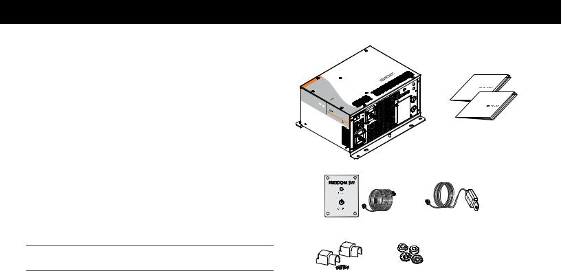
Materials List
The Freedom SW 3000 ships with the following items:
•one Freedom SW 3000 unit,
•owner’s and installation guides,
•Battery Temperature Sensor (BTS),
•Freedom SW remote panel with 25-foot communications cable,
•DC terminal covers (one red, one black) with two sets of screws, and
•two sets of nuts and washers for the DC terminals.
NOTE: If any of the items are missing, contact Xantrex or any authorized Xantrex dealer for replacement. See “Contact Information” on page i.
IMPORTANT: Keep the carton and packing material in case you need to return the Freedom SW 3000 for servicing.
F |
|
RE |
|
E |
|
D |
|
O |
|
M |
S |
|
W |
3 |
|
|
|
|
|
0 |
|
|
|
|
|
|
0 |
|
|
|
|
|
|
0 |
|
|
|
F |
|
|
|
|
|
REE |
|
|
|
|
|
|
DO |
|
|
S |
|
|
|
MS |
|
BT |
|
|
|
W |
3 |
REM |
|
|
|
|
000 |
|
|
Freedom SW 3000
Installation and
Owner’s Guides
BTS
Remote Panel with communications cable
DC terminal covers |
nuts and washers |
with screws |
|
Figure 1 Materials List
975-0545-01-01 |
1 |

Introduction
About the Freedom SW 3000
Inverter/Charger
The Freedom SW 3000 is a convenient combination of an inverter, multistage battery charger, and transfer switch in one electronic device.
•As an inverter, the Freedom SW 3000 provides true sine wave power for your microwave, entertainment system, computer, and other loads. This power is identical to the AC source provided from the utility grid (power company).
•Some of the benefits of true sine wave power include consistent cooking in your microwave, handling of sensitive loads such as your TV set, dimmer switches, and appliances with speed controls.
•As a 150 amp power-factor corrected charger, the Freedom SW 3000 quickly and efficiently recharges your batteries.
•Unique split phase design transfers up to 7.2 kW of incoming qualified AC power.
Premium Power and Ease of Use
For managing your onboard power system, the Freedom SW 3000 provides superior features and rugged durability combined with ease of use. The Freedom SW 3000:
•Produces 120 volts AC at up to 3000 watts continuous with a 6000watt surge for ten seconds,
•Provides three-stage charging with 150 amps of output and charge formulas for flooded, gel, and AGM deep cycle batteries plus equalization for flooded batteries,
•Powers sensitive entertainment electronics using true sine wave power,
•Allows split phase input transfers of two legs of 30 amps to make full use of the available AC power,
•Has easy-to-read indicator lights on the front panel,
•Has automatic cooling fans, and
•Provides power sharing which reduces the charging current to prevent unnecessary tripping of an AC input breaker.
2 |
Freedom SW 3000 Owner’s Guide |

Introduction
How the Freedom SW 3000 Inverter/Charger
Works
The Freedom SW 3000 is designed to:
•invert,
•charge, and
•accept both split phase and dual input.
With AC input available from the utility grid or a generator, power is passed through the Freedom SW 3000 Inverter/Charger to operate connected AC loads. The remaining AC power not used by loads is converted to DC power and used to charge batteries.
If AC input power becomes disconnected, fails, or falls out of specification and is no longer qualified as good AC, a quick transfer takes place and the Freedom SW 3000 begins converting DC power from the batteries into AC power, to continue to supply power to the AC loads.
Inverting
The Freedom SW 3000’s inverting function produces 120 volts AC from your batteries at 3000 watts continuous with 6000 watts of surge power to start loads like pumps and refrigerators.
Charging
The Freedom SW 3000’s charging function:
•produces 150 amps to charge your batteries, and
•equalizes flooded, lead acid batteries.
Built-in Charge Formulas For the unit to perform at the highest level, the batteries must be charged correctly. The Freedom SW 3000 has optimized algorithms for flooded, gel, and AGM batteries.
Battery Temperature Sensor Since battery temperature is a key factor in correct charging, the charging formula must be adjusted (automatically and in real time) according to the actual battery temperature to ensure that batteries are fully charged, but not overcharged. For this reason, Xantrex® has included a battery temperature sensor with your Freedom SW 3000 and has temperature compensated the charge formula.
Manual Equalization Over a period of time, the cells in a flooded battery can develop uneven chemical states. This can result in a weak (undercharged) cell which, in turn, can reduce the overall capacity of the battery. To improve the life and performance of a non-sealed, flooded battery, the Freedom SW 3000’s multi-stage charging cycle includes a manual equalize mode that can be used, if recommended by the battery manufacturer.
Dead Battery Charging Another feature that the Freedom SW 3000 includes is dead battery charging. The Freedom SW 3000—unlike many chargers—has the ability to recharge batteries even if the battery voltage is very low, i.e., as low as 5 volts.
975-0545-01-01 |
3 |
Introduction
Load Management The Freedom SW 3000 has a built-in transfer relay that connects your inverter output or AC input from the utility grid or generator to your loads. Because the usual AC power sources such as campground outlets or small generators often have limited current availability, having the capability to manage your AC loads is extremely valuable. The Freedom SW 3000 provides a number of features to facilitate this:
•The charger is power factor corrected to use AC current as efficiently as possible and only requires 22 amps to provide rated charger output. Minimizing the AC current used by the charger means more current is available for your AC loads.
•Freedom SW 3000 has a power share feature which prioritizes your AC loads by reducing the charge current and maintaining the total input current to less than your breaker setting or the breaker setting.
•Occasionally, AC input sources have low voltage. To avoid loading these weak sources any further, the charger automatically reduces its AC current draw as the AC voltage approaches the minimum acceptable level.
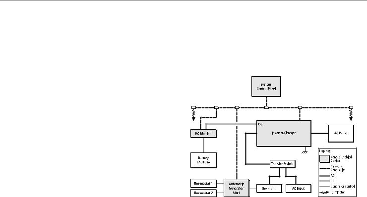
Xanbus® System
The Xanbus system includes the Freedom SW 3000 and other Xanbusenabled devices. The Freedom SW 3000 is the device in a Xanbus system that typically provides network power—500 mA at 12 volts DC. All of the Xanbus-enabled devices, such as the Freedom SW 3000, the System Control Panel (SCP), and the Automatic Generator Starter (AGS) are able to communicate their settings and activity to each other. See Figure 1.
AC Out
AC In
Figure 1 Typical Xanbus System Diagram
4 |
Freedom SW 3000 Owner’s Guide |

Introduction
The Xanbus-enabled designation means that this product works on a Xanbus network. Xanbus-enabled products are:
•Easy to use. The Xanbus network simplifies operation and automates routine tasks.
•Reliable. Software control eliminates analog signalling errors.
•Accurate. Digital information is less susceptible to interference and line loss.
•Upgradeable. Software upgrades mean your purchase will remain up to date.
For detailed instructions and a complete list of Xanbus-enabled devices, visit www.xantrex.com
Comprehensive Electronic Protection
Freedom SW 3000 is approved to meet a number of safety standards including UL 458 and CSA C22.2 No. 107.1. See “Regulatory Approvals” on page 63 for more information.
Freedom SW 3000 is equipped with numerous protection features to ensure safe operation.
Protection feature |
This feature… |
Battery over-voltage |
Keeps the battery voltage from getting too |
protection |
high in charge mode. Shuts the inverter off in |
|
invert mode. |
Battery under-voltage |
Prevents inverter from discharging your |
protection |
batteries too low. The inverter doesn’t run if |
|
battery voltage is too low. |
Over-temperature |
Protects the unit from overheating by either |
protection |
derating (charge mode) or by shutting down |
|
(invert mode). See “Invert Power Derating |
|
versus Ambient Temperature” on page 64. |
Automatic overload |
Protects the unit from excessive loads. The |
protection |
unit will provide 6000 watts (twice the rated |
|
load) for up to ten seconds, and then protect |
|
itself by shutting down. See “Inverter |
|
Specifications” on page 61 for more |
|
information. |
Short circuit protection |
Protects the unit by shutting it down. |
975-0545-01-01 |
5 |
Freedom SW 3000 Inverter/Charger Features
This section describes the different parts of the Freedom SW 3000.
Front and Side Panels
Front Panel
Controls and
Status LEDs
3000W |
SINEWAVE |
|
|
|
|
|
|
|
INVEFREEDOM |
|
|
|
TER/CHARGER |
||
|
|
SW |
3000 |
|
|
|
|
Model
Number
FGA
Number
8FSW3000 153000
Inverter |
|
|
|
|
|
|
|
|
|
|
|
|
|
|
|
||
Nominal |
|
|
|
|
|
|
|
|
|
|
|
|
|
|
|
|
|
Nominal DCMode: |
|
|
|
|
|
|
|
|
|
|
|
|
|||||
MaxNominal. |
AC |
OutputOperating |
|
|
|
|
|
|
|
|
|
|
|
||||
Max. |
|
AC |
|
|
|
|
|
|
|
|
|
|
|
||||
Max.ContinuousOutput |
|
|
|
|
12 |
|
|
|
|
|
|
|
|||||
|
Operating |
ACVoltage:Voltage: |
|
|
|
|
|
|
|
||||||||
Max.Continuous3000 |
ACInputFrequency:Output |
60Vac |
|
|
|
|
|
|
|||||||||
MaxInput:. |
|
|
DC |
|
|
|
120 |
Vdc |
|
|
|
|
|
|
|||
Max.DCOutput |
VA at |
|
|
|
|
|
Hz |
|
,1Ø |
|
|
|
|
||||
|
AmbientInputSurge |
25°COutputCurrent:atCurrent:32025 A |
|
|
|
|
|||||||||||
Charger |
|
Voltage:Power |
(5s |
NominalA |
|
|
|
|
|
||||||||
Power |
ACMode:Temperature: |
duration): |
|
|
|
|
|
||||||||||
Nominal |
|
|
|
|
|
16 |
Vdc |
|
|
|
DC |
|
|
|
|
||
MaxCharging. Factor:Input |
|
|
|
50°C |
|
|
6000 VA |
|
|
||||||||
|
|
DC |
> |
0.Voltage:95 |
120 |
|
|
|
|
|
|||||||
MaxNominal.ContinuousOutput |
|
Vac |
|
|
|
|
|
|
|
||||||||
30 AAC |
|
AC |
Input:BatteryVoltage |
|
|
|
|
|
|
|
|
||||||
|
perInput |
Range: |
, |
60 Hz, |
|
|
|
||||||||||
|
|
line |
|
|
150 A |
|
|
1Ø |
|
|
|||||||
|
|
|
|
DualCurrent: |
30ChargerA |
DC5.0- |
|
|
|
|
|||||||
INSTALLATIONspecified ininv |
|
per |
line |
SplitCurrent atVdc |
|
|
|||||||||||
Mount this |
|
|
|
|
|
|
|
|
16.0 |
|
|
|
|||||
CAUTION:incovera or erter/chargerinst |
|
|
|
Phase, |
|
|
|
||||||||||
user |
|
|
the |
|
|
|
|
|
|
|
|
|
|
|
|
||
|
clearancenote ventilationREQUIREMENTS:the |
|
|||||||||||||||
|
|
zero- |
|
|
To allation |
only |
|
|
|
|
|
|
|
||||
result. Doobstruct |
reduce |
guidein the |
|
|
|
|
|
||||||||||
WARNING:DC xpose to |
|
|
riskprovidedof orientations. |
|
|||||||||||||
Usesourcesserviceable |
compartme . |
.fire, |
do |
|
|
|
|||||||||||
|
|
only . |
|
Shock |
rainopeningsnt |
|
|
|
|
||||||||
typesspecifiedgroundin Disconnect- |
hazard.sprayOverhea. |
not |
|
|
|||||||||||||
lead- |
|
|
fail to |
parts. |
|
|
or |
|
|
Do |
|
not |
|
||||
may |
fault |
Energized |
Do |
not |
|
|
may |
||||||||||
this |
the |
|
|
|
|
|
tingmount |
||||||||||
|
|
equipmentacid .installationcircuitsourcesfrom |
|
open. |
|
|
|||||||||||
causing |
personal |
operate |
|
|
|
|
|
both |
|
and |
|||||||
|
|
|
. |
|
|
|
interrupters |
|
|
||||||||
|
|
|
batteriesRefer |
|
guide |
|
before |
|
ACNo |
|
|||||||
DANGER:install in |
|
Othermaproperlysupplied(GFCI).servicing. |
|||||||||||||||
|
|
|
an |
|
injury |
|
banual.when |
|
Other |
|
|||||||
euipment is areaTo |
|
and |
|
ttery |
|
|
|
|
|||||||||
|
|
|
|
requiinreduce |
damageChargeconnected |
|
|||||||||||
|
|
|
|
|
|
redwhich. |
the risk |
|
types. mayonly |
|
to |
||||||
|
|
|
|
|
|
|
|
|
ignition-of |
|
|
|
burst |
|
|||
|
|
|
|
|
|
|
|
|
|
|
|
explosion, |
do not |
||||
|
|
|
|
|
|
|
|
|
|
|
|
protected |
|
||||
Serial |
Number |
|
China
Date of |
Manufacture |
|
3000 SW FREEDOM 
FREEDOM |
SW |
|
3000 |
|
|
FREEDOM |
Fault |
|
SW |
||
|
||
|
3000 |
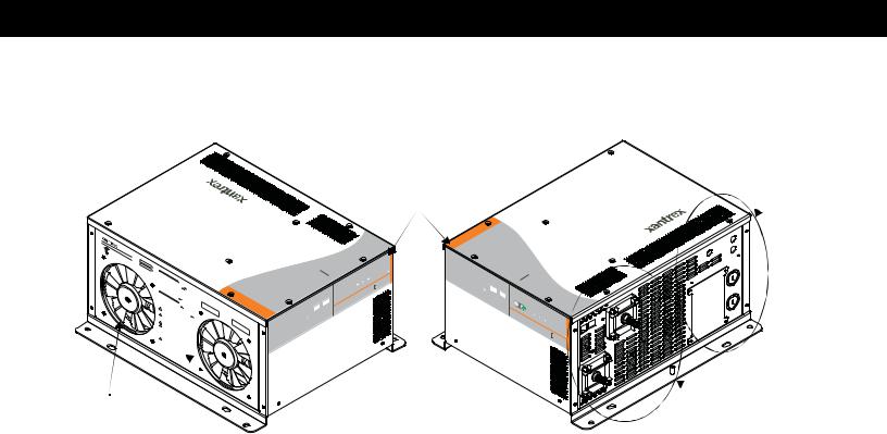
Cooling Fans
Figure 2 Freedom SW 3000 Front and Side Panels
AC
Compartment
 Side
Side
 DC Terminal Side
and Ground Terminal Stud
6 |
Freedom SW 3000 Owner’s Guide |
Freedom SW 3000 Inverter/Charger Features
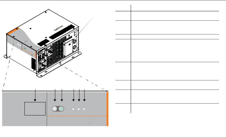
Front and Side Panels
Before you begin to operate the Freedom SW 3000, review the front panel features shown in Figure 3 and described in the next table. A detailed view of the lights and buttons on the front panel is shown in Figure 4 and described in the table next to it.
3 |
1 |
|
3000W |
SINEWA |
|
|
|
|
|
|
FREE |
|
|
|
||
|
VE |
DOM |
|
|
||
|
|
INVER |
|
|
|
|
|
|
|
TER/CHARGER |
|||
|
|
|
|
|
SW |
3000 |
|
|
|
|
|
|
|
Model
Number
FGA
Number
FSW3000 8153000
Inverter |
|
|
|
|
|
|
|
|
|
|
|
|
|
|
|
||
Nominal |
|
|
|
|
|
|
|
|
|
|
|
|
|
|
|
|
|
Nominal DCMode: |
|
|
|
|
|
|
|
|
|
|
|
|
|||||
MaxNominal. |
AC |
OutputOperating |
|
|
|
|
|
|
|
|
|
|
|
||||
Max. |
|
AC |
|
|
|
|
|
|
|
|
|
|
|
||||
Max.ContinuousOutput |
|
|
|
|
12 |
|
|
|
|
|
|
|
|||||
|
Operating |
ACVoltage:Voltage: |
Vdc |
|
|
|
|
|
|||||||||
MaxInput:. |
|
|
DC |
|
|
|
120 |
|
|
|
|
|
|||||
Max.Continuous3000 |
ACInputFrequency:Output |
60Vac |
|
|
,1Ø |
|
|
|
|||||||||
Max.DCOutput |
VA at |
|
|
|
|
|
Hz |
|
|
|
|
||||||
|
|
InputSurge |
25°COutputCurrent:Current:at |
25 A |
|
|
|
|
|||||||||
|
Ambient |
|
|
Power |
(5s |
|
|
320 A |
|
|
|
|
|
||||
Charger |
|
Voltage: |
16 |
Nominal |
DC |
|
|
|
|
||||||||
Nominal |
|
|
|
|
|
Vdc |
|
|
|
|
|
|
|
|
|||
Power |
|
ACMode:Temperature: |
|
5duration): |
|
|
|
|
|
||||||||
MaxCharging. Factor:Input |
|
|
|
0°C |
|
|
6000 VA |
|
|
||||||||
|
|
DC |
> |
0.Voltage:95 |
120 |
|
|
|
|
|
|||||||
MaxNominal.ContinuousOutput |
|
|
|
|
|
|
|
|
|
|
|||||||
30 |
AC |
|
AC |
|
|
Voltage |
|
Vac |
|
|
|
|
|
|
|
||
A |
|
Input |
|
|
|
|
,60 |
|
|
|
|
||||||
|
per line |
Input:Battery |
|
|
|
|
Hz, |
|
|
|
|||||||
Mount |
|
DualCurrent:150 AChargerRange: |
|
|
|
1Ø |
|
|
|||||||||
this |
|
|
|
30 A |
|
per |
DC5.0-16 |
|
|
|
|||||||
|
|
|
|
|
|
|
|
|
|
|
|
.0 |
|
|
|
||
INSTALLATIONspecified ininv |
|
|
line SplitCurrent atVdc |
|
|
||||||||||||
|
|
|
|
the |
|
|
|
|
|
|
|
Phase, |
|
|
|
||
CAUTION:incovera or erter/chargerinst |
only |
|
|
|
|
|
|||||||||||
resultzero. - |
|
|
To allation |
|
|
|
|
|
|
|
|||||||
user |
|
Doobstruct |
reduce |
guidein the |
|
|
|
|
|
||||||||
|
clearancenot ventilationREQUIREMENTS:the |
|
|||||||||||||||
WARNING:DC expose to |
|
|
riskprovidedof orientations. |
|
|||||||||||||
Usesourcesserviceable |
compartme . |
|
.fire, |
do |
|
|
|
||||||||||
|
|
only . |
|
Shock |
rainopeningsnt |
|
not |
|
|||||||||
|
|
|
|
|
|
parts. |
|
|
or |
|
|
|
Do |
|
|||
typesspecifiedgroundin Disconnect- |
hazard.spray. |
|
|
not |
|
|
|||||||||||
this |
may |
the |
fault |
|
|
|
DoOverheatingmount |
||||||||||
lead- |
|
|
fail to |
|
|
Energized |
|
not |
|
|
may |
||||||
|
|
equipmentacid .installationcircuitsourcesfrom |
|
open. |
No |
|
|||||||||||
causing |
|
|
|
operate |
|
|
|
|
|
both |
AC |
|
|||||
install |
batteriesRefer. |
to proguideinterruptersbefore |
|
|
|
||||||||||||
personal |
|
Other |
|
perly |
|
|
|
|
servicinand |
||||||||
DANGER:in |
|
|
|
supplied(GFCI). |
|
g. |
|||||||||||
|
|
|
an |
|
injury |
|
manualb .when |
|
Other |
|
|||||||
euipment is areaTo |
|
|
and |
|
ttery |
|
|
|
|
|
|||||||
|
|
|
|
requi |
inreduce |
|
|
|
Chargeconnecte |
|
|||||||
|
|
|
|
|
|
redwhich. |
|
risk |
|
|
|
may |
burst |
to |
|||
|
|
|
|
|
|
|
|
|
ignition-of |
|
|
|
|||||
|
|
|
|
|
|
|
|
|
|
|
|
protecteexplosion, |
do not |
||||
|
|
|
|
|
|
|
|
|
|
|
|
|
|
|
|
||
Serial |
Number |
|
China
Date of |
Manufacture |
|
SW FREEDOM
Xanbus
3000
|
|
AC/ Fault |
|
|
er |
Cha |
rge |
In |
vert |
|
|
On |
|
|
|
ter |
|
|
|
Inver |
|
|
|
Enable |
|
|
SW |
Reset |
|
|
|
FREEDOM |
|||
rface Inte
 3000
3000
2
Figure 3 Isometric View of the Front Panel and Fans
Item Description
1Front Panel contains the Xanbus interface ports for connecting Xanbus-enabled devices, the Inverter Enable and Reset buttons, as well as various LED status lights. See Figure 4.
2Mounting holes are used for mounting the unit. A total of eight holes are provided on the unit.
3Two variable-speed cooling fans are used to cool the unit. Fan speed control is based on internal temperature of critical components. The two exhaust fans control airflow though the transformer and power compartments of the unit. Ensure at least six inches of clearance for proper ventilation.
975-0545-01-01 |
7 |
Freedom SW 3000 Inverter/Charger Features
|
|
Item |
Description |
1 |
2 |
1 |
DC terminals. See “AC and DC Side Panels” on page 9 |
|
|
|
for more information. |
|
|
2 |
AC wiring compartment access panel with |
|
|
|
compartment cover on. See “AC and DC Side Panels” on |
|
|
|
page 9 for more information. |
FREEDOM |
SW |
|
|
|
|
|
|
|
|
3 |
3000 |
|
|
|
|
|
|
4 |
|
|
|
|
|
|
|
|
FREEDOM |
Fault |
|
|
|
|
|
|
SW |
|
|
|
|
|
|
|
|
|
|
|
|
|
|
|
|
3000 |
|
|
|
|
|
|
|
|
|
|
|
|
|
5 |
|
8 |
7 |
6 |
5 |
4 |
3 |
6 |
|
|
||||||
|
|
|
|
|
|
|
7 |
|
|
|
Inverter |
Inverter |
AC/ |
|
8 |
|
|
Reset |
Enable |
|
|||
|
|
On |
Charge Fault |
||||
|
|
|
|
||||
Xanbus Interface |
|
|
|
|
|
|
|
Fault light illuminates if a fault condition occurs. AC/Charge light illuminates when the Freedom SW 3000 is in charge mode and is producing DC output to charge your batteries. AC/Charge also illuminates when you are connected to an AC source like the utility grid or a generator and the AC is qualified.
Inverter On indicates the unit is in invert mode. NOTE: If AC is present and invert mode is enabled, this
light remains illuminated even though AC power is being passed through.
Inverter Enable button is used to switch the inverter on and off.
Reset button is used to clear any active faults if pressed momentarily. If held down for more than three seconds, the unit will reset (reboot) itself.
Xanbus Interface ports are used to connect Xanbusenabled devices including the optional SCP and AGS.
FREEDOM SW 
 3000
3000
Figure 4 Isometric View of the Front Panel and AC/DC Side Panel
8 |
Freedom SW 3000 Owner’s Guide |
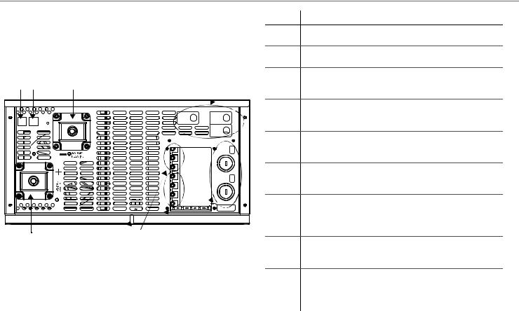
AC and DC Side Panels
The DC side of the Freedom SW 3000 has the equipment ground lug, the positive (+) battery terminal, and the negative (–) battery terminal plus the remote network com port and battery temperature sensor com port.
1 2
REM BTS
3
WARNING: INCORRECT BATTERY
PO
AL
RIT
W Y
ILL
.ITNU OT EGMAAD CAUSE
5
RTERINVE OUTPUT AC |
1 LINE |
INPUT AC |
|
2 LINE |
INPUT CA |
Wiring box cover must be in place during use to reduce risk of injury to persons
AC
IN
AC
OUT
AC GROUNDS (BEHIND COVER)
4 |
9 |
8 |
7 |
6 |
Figure 5 AC and DC Side Panel
Freedom SW 3000 Inverter/Charger Features
Item Description
1Remote (REM) jack provides connection for the Freedom Sine Wave remote panel (supplied).
2Battery temperature sensor (BTS) jack provides connection for the battery temperature sensor (supplied).
3Negative (–) DC terminal connects to the negative battery cable (black). Install a DC terminal cover (supplied) over the terminal.
4Positive (+) DC terminal connects to the positive battery cable (red). Install a DC terminal cover (supplied) over the terminal.
5AC Input 1, AC Input 2, and Inverter AC Output circuit breaker switches allow you to reset the circuit breakers when they trip.
6AC knockouts provide access for AC cables (both input and output wiring). Detach the knockout covers and install the strain-relief clamps (supplied).
7AC Output terminal block is a screw-type terminal block for attaching AC output wires. Each slot is labeled N1 for Neutral 1, L1 and L2 for Lines 1 and 2, and N2 for Neutral 2.
8AC Input terminal block is a screw-type terminal block for attaching AC input wires. Each slot is labeled
N for Neutral and L1 and L2 for Lines 1 and 2.
9Chassis ground lug connects the chassis of the FSW3000 to your system’s chassis grounding point.
Not |
All Ground terminals are along the tab at the bottom of |
shown |
the opening to the AC wiring compartment access panel. |
975-0545-01-01 |
9 |
Freedom SW 3000 Inverter/Charger Features
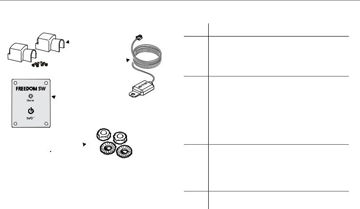
Supplied Accessories
 1
1
2 
 3
3
4
Figure 6 Supplied Accessories
NOTE: If any of the supplied accessories are missing, contact Xantrex or any authorized Xantrex dealer for replacement. See “Contact Information” on page i.
Item Description
1Two DC terminal covers are supplied to prevent accidental contact with the DC cable connectors after installation. The red cover is for the positive cabling terminal, and the black cover is for the negative cabling terminal.
2BTS, the Battery Temperature Sensor consists of:
•Connector plugs into the BTS jack on the Freedom SW 3000.
•Sensor cable is 25 feet (7.6 meters).
•Sensor can be mounted on the side of the battery case or on the negative battery terminal.
NOTE: The BTS continuously measures the temperature of the battery and adjusts the charger output for a more accurate, temperature-compensated charge.
3Freedom Sine Wave remote panel (with 25-ft communications cable) is functionally similar to the Inverter Enable button on the unit’s front panel. It enables and disables the Freedom SW 3000’s inverter mode remotely. Connects to the REM jack on the Freedom SW 3000.
4Two sets of nuts and washers are used to secure DC cable ends to the DC terminals.
10 |
Freedom SW 3000 Owner’s Guide |

Freedom SW 3000 Inverter/Charger Features
Optional System Accessories and Network Components
System accessories can be used with the Freedom SW 3000 in a Xanbus system. The SCP provides configuration and monitoring capability for Xanbus-enabled devices such as the Freedom SW 3000. AGS automatically starts and stops your generator.
Table 1 provides the part numbers for the system accessories.
Table 1 System Accessories
Accessory |
Part number |
SCP |
809-0910 |
AGS |
809-0915 |
These optional accessories and network components are available from any authorized Xantrex dealer or at www.xantrex.com. Detailed information on planning and installing your network is available in the Xanbus System Installation Guide. This guide is available for downloading at www.xantrex.com
Consult with your local system designer to determine what network components will be needed for your specific installation. Table 2 provides a list of network components and part numbers. Pre-made cables are available in standard lengths ranging from 3 feet to 75 feet.
Table 2 Network Components and Part Numbers
Network Component |
Part Number |
Network cable 3 ft. (0.9 m) |
809-0935 |
Network cable 25 feet (7.6 m) |
809-0940 |
Network cable 75 feet (22.9 m) |
809-0942 |
975-0545-01-01 |
11 |

Operating The Freedom SW 3000
This section contains detailed information and procedures for using your Freedom SW 3000.
If you’re using the SCP to operate or monitor the status of the unit, also refer to the System Control Panel Owner’s Guide.
LIMITATIONS ON USE
•Do not use in connection with life support systems or other medical equipment or devices.
•Do not use in ambulances or other life-saving emergency vehicles.
Failure to follow these instructions can result in death or serious injury.
Operating the Freedom SW 3000 with the Optional System Control Panel (SCP)
The SCP provides operating, configuration, and monitoring capability for your Xanbus system.
The System Control Panel:
•Monitors activity throughout your onboard power system.
•Displays the latest information about your inverter/charger, battery charge level, battery charge output, and generator start and stop activity.
•Displays the settings for each Xanbus-enabled device in the system.
•Enables you to adjust the settings for each Xanbus-enabled device in the system.
•Preserves all of its settings if system power is interrupted. After power is restored, you don’t have to reconfigure the SCP or any of the Xanbus-enabled devices connected to it.
This section provides information on operating the Freedom SW 3000 with the System Control Panel. Please refer to the System Control Panel Owner’s Guide for complete information on using the System Control Panel.
12 |
Freedom SW 3000 Owner’s Guide |
 Loading...