


 Loading...
Smart choice for power
C35
C40
C60
Owner’s Manual
C-Series
Multifunction
DC Controller
www.xantrex.com

C-Series Multifunction
DC Controller
Owner’s Guide
About Xantrex
Xantrex Technology Inc. is a world-leading supplier of advanced power electronics and controls with products from 50 watt mobile units to one MW utility-scale systems for wind, solar, batteries, fuel cells, microturbines, and backup power applications in both grid-connected and stand-alone systems. Xantrex products include inverters, battery chargers, programmable power supplies, and variable speed drives that convert, supply, control, clean, and distribute electrical power.
Trademarks
C-Series Multifunction DC Controller is a trademark of Xantrex International. Xantrex is a registered trademark of Xantrex International.
Other trademarks, registered trademarks, and product names are the property of their respective owners and are used herein for identification purposes only.
Notice of Copyright
C-Series Multifunction DC Controller Owner’s Guide © November 2003 Xantrex International. All rights reserved.
Disclaimer
UNLESS SPECIFICALLY AGREED TO IN WRITING, XANTREX TECHNOLOGY INC. (“XANTREX”)
(a)MAKES NO WARRANTY AS TO THE ACCURACY, SUFFICIENCY OR SUITABILITY OF ANY TECHNICAL OR OTHER INFORMATION PROVIDED IN ITS MANUALS OR OTHER DOCUMENTATION.
(b)ASSUMES NO RESPONSIBILITY OR LIABILITY FOR LOSS OR DAMAGE, WHETHER DIRECT, INDIRECT, CONSEQUENTIAL OR INCIDENTAL, WHICH MIGHT ARISE OUT OF THE USE OF SUCH INFORMATION. THE USE OF ANY SUCH INFORMATION WILL BE ENTIRELY AT THE USER’S RISK.
Date and Revision
November 2003 Revision D
Part Number
975-0004-01-02 Rev D
Contact Information
Telephone: |
1 800 670 0707 |
(toll free North America) |
|
1 360 925 5097 |
(direct) |
Fax: |
1 800 994 7828 |
(toll free North America) |
|
1 360 925 5143 |
(direct) |
Email: |
customerservice@xantrex.com |
|
Web: |
www.xantrex.com |
|

About This Guide
Purpose
The purpose of this Guide is to provide explanations and procedures for installing, operating, maintaining, and troubleshooting the C-Series Multifunction DC Controller.
Scope
This Guide provides safety guidelines, detailed planning and setup information, procedures for installing the inverter, as well as information about operating and troubleshooting the unit. It does not provide details about particular brands of batteries. You need to consult individual battery manufacturers for this information.
Audience
This Guide is intended for anyone who needs to install and operate the C-Series Multifunction DC Controller. Installers should be certified technicians or electricians.
Organization
This Guide is organized into four chapters and three appendices.
Chapter 1 describes features and functions of the C-Series Multifunction DC Controller.
iii
About This Guide
Chapter 2 contains information and procedures to install C-Series Multifunction DC Controller.
Chapter 3 contains information about the operation of a C-Series Multifunction DC Controller.
Chapter 4, “Troubleshooting” contains information about identifying and resolving possible problems with systems using a C-Series Multifunction DC Controller.
Appendix A, “Specifications” provide the specifications for the C-Series Multifunction DC Controller.
Appendix B, “Batteries” describes types of batteries.
Appendix C, “Diversion Loads” provides additional information about Diversion Loads.
Conventions Used
The following conventions are used in this guide.
WARNING
Warnings identify conditions that could result in personal injury or loss of life.
CAUTION
Cautions identify conditions or practices that could result in damage to the unit or to other equipment.
Important: These notes describe an important action item or an item that you must pay attention to.
iv |
975-0004-01-02 Rev D |

About This Guide
Abbreviations and Acronyms
ASC |
Authorized Service Center |
|
|
BTS |
Battery Temperature Sensor |
|
|
CM |
C-Series Meter |
|
|
CM/R |
C-Series Meter - Remote |
|
|
DC |
Direct Current |
|
|
LCD |
Liquid Crystal Display |
|
|
LED |
Light Emitting Diode |
|
|
LVD |
Low Voltage Disconnect |
|
|
LVR |
Low Voltage Reconnect |
|
|
RE |
Renewable Energy |
|
|
Related Information
You can find more information about Xantrex Technology Inc. as well as its products and services at www.xantrex.com.
975-0004-01-02 Rev D |
v |
vi

Important Safety Instructions
WARNING
This manual contains important safety instructions that should be followed during the installation and maintenance of this product. Be sure to read, understand, and save these safety instructions.
General Safety Instructions
•All electrical work must be done in accordance with local, national, and/or international electrical codes.
•Before installing or using this device, read all instructions and cautionary markings located in (or on) this guide, the controller, the batteries, PV array, and any other equipment used.
•This product is designed for indoor mounting only. Do not expose this unit to rain, snow or liquids of any type. In outdoor installations, the C-Series controller must be installed in a rainproof enclosure to eliminate exposure to rain or water-spray.
•To reduce the chance of short-circuits, use insulated tools when installing or working with the inverter, the controller, the batteries, or any DC source (e.g., PV, hydro, or wind).
•Remove all jewelry. This will greatly reduce the chance of accidental exposure to live circuits.
•The controller contains more than one live circuit (batteries and PV array, wind, or hydro). Power may be present at more than one source.
•This product contains no user serviceable parts. Do not attempt to repair this unit unless fully qualified.
975-0004-01-02 Rev D |
vii |

Safety
Battery Safety Information
•Always wear eye protection, such as safety glasses, when working with batteries.
•Remove all jewelry before working with batteries.
•Never work alone. Have someone assist you with the installation or be close enough to come to your aid when working with batteries.
•Always use proper lifting techniques when handling batteries.
•Always use identical types of batteries.
•Never install old or untested batteries. Check each battery’s date code or label to ensure age and type.
•Batteries should be installed in a well-vented area to prevent the possible buildup of explosive gasses. If the batteries are installed inside an enclosure, vent its highest point to the outdoors.
•When installing batteries, allow at least 1 inch of air space between batteries to promote cooling and ventilation.
•NEVER smoke in the vicinity of a battery or generator.
•Always connect the batteries first, then connect the cables to the inverter or controller. This will greatly reduce the chance of spark in the vicinity of the batteries.
•Use insulated tools when working with batteries.
•When connecting batteries, always verify proper voltage and polarity.
•Do not short-circuit battery cables. Fire or explosion can occur.
•In the event of exposure to battery electrolyte, wash the area with soap and water. If acid enters the eyes, flood them with running cold water for at least 15 minutes and get immediate medical attention.
•Always recycle old batteries. Contact your local recycling center for proper disposal information.
viii |
975-0004-01-02 Rev D |
Battery Safety Information
CAUTION:
A battery can produce the following hazards to personal safety:
•electrical shock,
•burn from high-short-circuit current, and/or
•fire or explosion from vented gasses.
Observe proper precautions when working with or around batteries.
975-0004-01-02 Rev D |
ix |
x

Contents
Important Safety Instructions - - - - - - - - - - - - - - - - - -vii
1 Introduction
Features - - - - - - - - - - - - - - - - - - - - - - - - - - - - - - - - - - - - - - - 2 Operating Modes - - - - - - - - - - - - - - - - - - - - - - - - - - - - - - - - - 3 Charge Control Mode - - - - - - - - - - - - - - - - - - - - - - - - - - - 4 Three-Stage Battery Charging - - - - - - - - - - - - - - - - - - - 4 Battery Temperature Compensation - - - - - - - - - - - - - - - 6 Manual or Auto Equalization Charge - - - - - - - - - - - - - - 6 Load Control Mode - - - - - - - - - - - - - - - - - - - - - - - - - - - - - 6
Controller Functions - - - - - - - - - - - - - - - - - - - - - - - - - - - - - - - 7 Photovoltaic Charge Controller - - - - - - - - - - - - - - - - - - - - - 7 Automatic PV Array Night Disconnect- - - - - - - - - - - - - 8 Diversion Controller - - - - - - - - - - - - - - - - - - - - - - - - - - - - 8 Diversion Loads - - - - - - - - - - - - - - - - - - - - - - - - - - - - 9 Load Controller - - - - - - - - - - - - - - - - - - - - - - - - - - - - - - 10 Low Voltage Disconnect - - - - - - - - - - - - - - - - - - - - - 11 Low Voltage Reconnect - - - - - - - - - - - - - - - - - - - - - - 11
Optional Accessories - - - - - - - - - - - - - - - - - - - - - - - - - - - - - 12
2 Installation
Pre-Installation - - - - - - - - - - - - - - - - - - - - - - - - - - - - - - - - - 14
Removing the Top Cover - - - - - - - - - - - - - - - - - - - - - - - - 14
Removing Knockouts - - - - - - - - - - - - - - - - - - - - - - - - - - 14
Mounting the Controller - - - - - - - - - - - - - - - - - - - - - - - - 16
Configuring the C-Series Controller - - - - - - - - - - - - - - - - - - - 18
Jumper Settings - - - - - - - - - - - - - - - - - - - - - - - - - - - - - - 18
Operating Mode Jumper- - - - - - - - - - - - - - - - - - - - - - 20
Voltage Jumper- - - - - - - - - - - - - - - - - - - - - - - - - - - - 20
xi

Contents
Automatic/Manual Battery Equalization (EQ) and Low Voltage Reconnect (LVR) Jumper - - - - - - - - - - - - - - 21
Adjusting the C-Series Voltage Settings - - - - - - - - - - - - - - - - - 22 Setting Voltage Parameters for Charge Control Mode- - - - - 22 Setting Voltage Parameters for Load Control Mode - - - - - - 24 Setting Voltage Parameters Diversion Control Mode - - - - - 26 Setting Voltage Parameters for Alkaline Batteries - - - - - - - 26 Using a Digital Voltmeter to Adjust Voltage Settings - - - - - 28
Equalization Charging- - - - - - - - - - - - - - - - - - - - - - - - - - - - - 30 Manual Equalization - - - - - - - - - - - - - - - - - - - - - - - - - - - 31 Automatic Equalization - - - - - - - - - - - - - - - - - - - - - - - - - 32 Terminating the Equalization Process - - - - - - - - - - - - - - - 33 Temperature Compensation - - - - - - - - - - - - - - - - - - - - - - - - - 33 Temperature Compensation Based on Battery Type - - - - - - 34 Automatic Battery Temperature Compensation - - - - - - - - - 34 Manual Battery Temperature Compensation - - - - - - - - - - - 36 Grounding - - - - - - - - - - - - - - - - - - - - - - - - - - - - - - - - - - - - - 37 Wiring - - - - - - - - - - - - - - - - - - - - - - - - - - - - - - - - - - - - - - - 38 DC Terminal Connector Locations - - - - - - - - - - - - - - - - - 38 Terminal Torque Requirements - - - - - - - - - - - - - - - - - 39 Wire Size and Over-current Protection Requirements - - - - - 39 Current Rating - - - - - - - - - - - - - - - - - - - - - - - - - - - - 39 Minimum Recommended Wire Gauge - - - - - - - - - - - - 40 Surge Protection - - - - - - - - - - - - - - - - - - - - - - - - - - - 40 Over-current Protection - - - - - - - - - - - - - - - - - - - - - - 41 Long-distance wire runs - - - - - - - - - - - - - - - - - - - - - - 42 Maximum One-way Distance and Wire Size - - - - - - - - 42 PV Charge Control Mode Wiring - - - - - - - - - - - - - - - - - - 44
Diversion Control Mode Wiring - - - - - - - - - - - - - - - - - - - 46 DC Load Control Mode Wiring- - - - - - - - - - - - - - - - - - - - 48 Installing Optional Accessories- - - - - - - - - - - - - - - - - - - - - - - 50 Installing a Digital Display - - - - - - - - - - - - - - - - - - - - - - - 50 Installing the Battery Temperature Sensor - - - - - - - - - - - - 51 Reinstalling the Faceplate - - - - - - - - - - - - - - - - - - - - - - - - - - 52
xii |
975-0004-01-02 Rev D |

Contents
3 Operation
Basic Operation - - - - - - - - - - - - - - - - - - - - - - - - - - - - - - - - - 54
LED Status Indicator - - - - - - - - - - - - - - - - - - - - - - - - - - - - - 55
Charge Control or Diversion Control Indications (Green) - - 56
Blinking Green - - - - - - - - - - - - - - - - - - - - - - - - - - - - 57
Solid Green - - - - - - - - - - - - - - - - - - - - - - - - - - - - - - 57
Equalization Mode Indication (Red/green) - - - - - - - - - 58
Load Control Indications (Red) - - - - - - - - - - - - - - - - - - - - 58
Blinking Red - - - - - - - - - - - - - - - - - - - - - - - - - - - - - 58
Solid Red- - - - - - - - - - - - - - - - - - - - - - - - - - - - - - - - 58
Error Mode Indication (Orange) - - - - - - - - - - - - - - - - - - - 59
Over-temperature Condition - - - - - - - - - - - - - - - - - - - 59
Over-Current Condition - - - - - - - - - - - - - - - - - - - - - - 59
Low-voltage Disconnect Condition - - - - - - - - - - - - - - 60
Reconnecting to Loads - - - - - - - - - - - - - - - - - - - - - - - - - - - - 60 Reset Switch - - - - - - - - - - - - - - - - - - - - - - - - - - - - - - - - - - - 61
4 Troubleshooting
PV Charge Control Troubleshooting - - - - - - - - - - - - - - - - - - - 64
Diversion Control Troubleshooting - - - - - - - - - - - - - - - - - - - - 66
Load Control Troubleshooting - - - - - - - - - - - - - - - - - - - - - - - 68
A Specifications
Electrical Specifications - - - - - - - - - - - - - - - - - - - - - - - - - - - 70
Features and Options Specifications - - - - - - - - - - - - - - - - - - - 71
Environmental Specifications - - - - - - - - - - - - - - - - - - - - - - - - 72
B Batteries
Battery Types - - - - - - - - - - - - - - - - - - - - - - - - - - - - - - - - - - 74
Automotive Batteries- - - - - - - - - - - - - - - - - - - - - - - - - - - 74
Maintenance-Free Batteries - - - - - - - - - - - - - - - - - - - - - - 74
Deep-Cycle Batteries- - - - - - - - - - - - - - - - - - - - - - - - - - - 74
Sealed Batteries - - - - - - - - - - - - - - - - - - - - - - - - - - - - - - 75
NiCad and NiFe Batteries - - - - - - - - - - - - - - - - - - - - - - - 76
975-0004-01-02 Rev D |
xiii |

Contents
Battery Sizing - - - - - - - - - - - - - - - - - - - - - - - - - - - - - - - - - - 76
Equalization Charging- - - - - - - - - - - - - - - - - - - - - - - - - - - - - 77
Equalization Setpoints (Non-Sealed Batteries Only) - - - - - - 79
C Diversion Loads
Diversion Load Types - - - - - - - - - - - - - - - - - - - - - - - - - - - - - 82
Warranty and Product Information
Warranty - - - - - - - - - - - - - - - - - - - - - - - - - - - - - - - - - - - - - 85
Disclaimer - - - - - - - - - - - - - - - - - - - - - - - - - - - - - - - - - - - - 86
Return Material Authorization Policy - - - - - - - - - - - - - - - - - - 87
Return Procedure - - - - - - - - - - - - - - - - - - - - - - - - - - - - - - - - 88
Out of Warranty Service - - - - - - - - - - - - - - - - - - - - - - - - - - - 88
Information About Your System - - - - - - - - - - - - - - - - - - - - - 89
Index- - - - - - - - - - - - - - - - - - - - - - - - - - - - - - - - - - - - - - - - - - 91
xiv |
975-0004-01-02 Rev D |

Figures
Figure 1-1 C-Series Multifunction DC Charge Controllers - - - - - - 2 Figure 1-2 3-stage Battery Charging Process - - - - - - - - - - - - - - - 5 Figure 1-3 PV Charge Controller - - - - - - - - - - - - - - - - - - - - - - - 7 Figure 1-4 Diversion Controller - - - - - - - - - - - - - - - - - - - - - - - - 9 Figure 1-5 Load Controller - - - - - - - - - - - - - - - - - - - - - - - - - - 11 Figure 1-6 Decal Displaying Load Control Voltage Settings - - - - 12 Figure 1-7 Optional Accessories - CM/R, CM, and BTS- - - - - - - 12 Figure 2-1 Removing the Front Cover - - - - - - - - - - - - - - - - - - - 14 Figure 2-2 C-Series Dimensions and Knockout Locations
(Not to Scale) - - - - - - - - - - - - - - - - - - - - - - - - - - - - 15 Figure 2-3 Mounting the C-Series Multifunction DC Controller - 17 Figure 2-4 Jumper Positions- - - - - - - - - - - - - - - - - - - - - - - - - - 18 Figure 2-5 Circuit Board Components - - - - - - - - - - - - - - - - - - - 19 Figure 2-6 Mode of Operation Jumper - - - - - - - - - - - - - - - - - - - 20 Figure 2-7 Voltage Selection Jumper- - - - - - - - - - - - - - - - - - - - 20 Figure 2-8 EQ/LVR Jumper and Reset Switch - - - - - - - - - - - - - 21 Figure 2-9 Bulk and Float Charge Potentiometers (pots)- - - - - - - 22 Figure 2-10 Bulk and Float Charge Settings for Charge/Diversion
Control Mode - - - - - - - - - - - - - - - - - - - - - - - - - - - - 23 Figure 2-11 Potentiometers with Decal for LVR and LVD Settings 24 Figure 2-12 LVR and LVD Settings for Load Control Mode- - - - - 25 Figure 2-13 R46 Resistor Location - - - - - - - - - - - - - - - - - - - - - - 26 Figure 2-14 Voltage Settings with R46 Resistor Clipped - - - - - - - 27 Figure 2-15 Test Points for Adjusting Voltage Using a DVM - - - - 29 Figure 2-16 Manual Equalization Settings - - - - - - - - - - - - - - - - - 30 Figure 2-17 Front Panel LED and Reset Switch Location - - - - - - - 31 Figure 2-18 Auto Equalization Settings - - - - - - - - - - - - - - - - - - - 32 Figure 2-19 Terminating the Equalization Charge - - - - - - - - - - - - 33 Figure 2-20 Grounding the C-Series Chassis - - - - - - - - - - - - - - - 37 Figure 2-21 DC Connection Terminals - - - - - - - - - - - - - - - - - - - 39
xv

Figures
Figure 2-22 AWG Wire Gauge Reference Chart - - - - - - - - - - - - - 40 Figure 2-23 PV Charge Control Mode Wiring - - - - - - - - - - - - - - 45 Figure 2-24 Diversion Control Mode Wiring - - - - - - - - - - - - - - - 47 Figure 2-25 Load Control Mode Wiring - - - - - - - - - - - - - - - - - - 49 Figure 2-26 Installing a Digital Display - - - - - - - - - - - - - - - - - - - 50 Figure 2-27 Installing the BTS - - - - - - - - - - - - - - - - - - - - - - - - - 51 Figure 2-28 Re-installing the CM Faceplate - - - - - - - - - - - - - - - - 52 Figure 3-1 C-Series Status LED and Reset Button Location - - - - 54 Figure 3-2 C-Series Front Panel Label - - - - - - - - - - - - - - - - - - - 55 Figure 3-3 Reset Switch - - - - - - - - - - - - - - - - - - - - - - - - - - - - 61
xvi |
975-0004-01-02 Rev D |

Tables
Table 2-1 Factory Default Settings for C-Series Controllers - - - - 19 Table 2-2 Variances in Charging Voltage based on
Battery Temperature - - - - - - - - - - - - - - - - - - - - - - - 35 Table 2-3 Minimum Wire Size - - - - - - - - - - - - - - - - - - - - - - - 41 Table 2-4 One-Way Wire Distance and Wire Size - - - - - - - - - - 43 Table 3-1 Battery Voltage LED Indicators - - - - - - - - - - - - - - - 56 Table 4-1 PV Charge Control Problems - - - - - - - - - - - - - - - - - 64 Table 4-2 Diversion Control Problems - - - - - - - - - - - - - - - - - - 66 Table 4-3 Load Control Problems - - - - - - - - - - - - - - - - - - - - - 68 Table A-1 Electrical Specifications- - - - - - - - - - - - - - - - - - - - - 70 Table A-2 Features and Options Specifications- - - - - - - - - - - - - 71 Table A-3 Environmental Specifications - - - - - - - - - - - - - - - - - 72 Table B-1 Typical Bulk and Float Setpoints for Batteries - - - - - - 79 Table C-1 Power Dissipation - - - - - - - - - - - - - - - - - - - - - - - - - 82
xvii
xviii
1Introduction
Chapter 1 describes features and functions of the C-Series Multifunction DC Controller.
For information on: |
See: |
|
|
“Features” |
page 2 |
|
|
“Operating Modes” |
page 3 |
|
|
“Controller Functions” |
page 7 |
|
|
“Optional Accessories” |
page 12 |
|
|
Introduction
Features
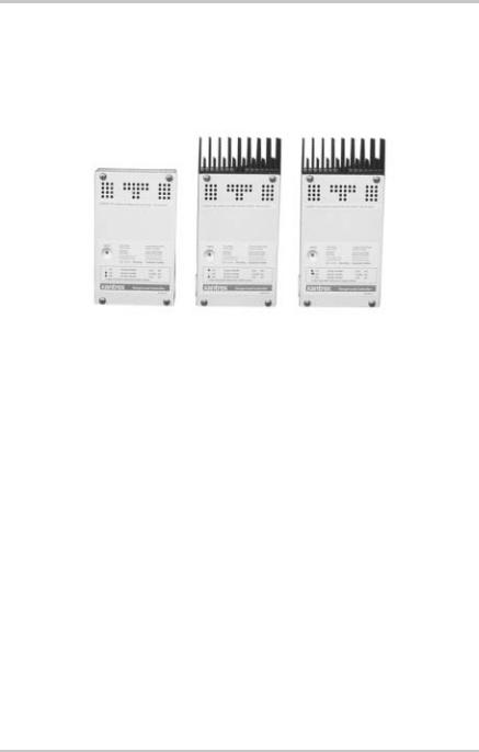
The C35/C40/C60 (C-Series) controllers can be used with 12-volt, 24-volt, or 48-volt DC systems (depending upon model) as Charge Controller or a Load Controller.
C35 |
C40 |
C60 |
|
|
Figure 1-1 C-Series Multifunction DC Charge Controllers
Numerous features are provided standard to maximize the performance of the system:
•Solid-state Pulse Width Modulated (PWM) charging process with three-stage control, temperature compensation, and manual or automatic equalization to maximize system performance and increase battery life.
•Multi color LED with easy to read mode/status label.
•Electronic overload and short-circuit protection with automatic and manual reset capability increases the reliability of unattended systems by eliminating blown fuses and tripped circuit breakers.
•Adjustment of charge setpoints is provided by rotary controls (potentiometers) with removable knobs. Calibrated scales and test points allow precise adjustments of settings.
•Over-temperature protection for the electronic circuitry when used in hot environments (over 113 °F/45 °C).
2 |
975-0004-01-02 Rev D |

Operating Modes
•Indoor-type, powder-coated enclosure, for wall mounting.
•Conformal-coated circuit boards, plated terminals, powder-coated metal components, and stainless steel fasteners improves tolerance to hostile environments.
•Meets National Electrical Code (NEC) and other international controller specifications.
•The C35, C40 and C60 models are UL listed to the U.S. UL Standard 1741 (1st edition), and Canada (CSA-C22.2 No. 107.1-95).
•2-year limited warranty.
Operating Modes
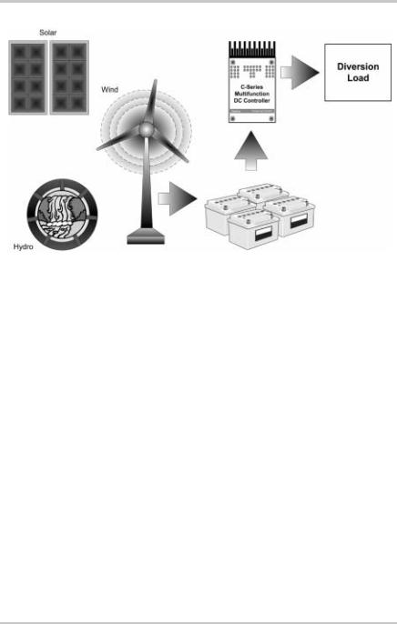
The DC controller is a critical component in any solar, wind or hydro power generation system and protects the batteries from over-discharge and over-charge conditions. The C-Series has two operating modes (Charge Control mode and Load Control mode determined by the Operating mode jumper (See Figure 2-5). These two different operating modes allow the C-Series to be installed and function as three different DC controllers.
•Charge Control Mode
•PV Charge Controller - controls charging in PV installations.
•Diversion Controller – used in PV, wind, or hydro installations to divert any excess energy to a diversion load and in the case of a wind or hydro generator, helps to prevent over-spin damage.
•Load Control Mode
•Load Controller - prevents damage to the battery from over-discharge during periods of poor charging or excessive loads.
975-0004-01-02 Rev D |
3 |

Introduction
Important: The C-Series controller cannot operate in more than one function at the same time. If several functions are required in a system, a dedicated controller must be used for each function.
Charge Control Mode
In the Charge Control mode, the C-Series controls how the batteries are charged by the DC source (solar, wind, or hydro). It uses a 3-stage charging protocol to maintain battery voltage at bulk and/or float levels.
When charging, the C-Series controller monitors the batteries and depending on how it is wired will regulate the PV current (as a PV Charge Controller) or divert excess energy from PV, hydro, or wind to a DC load (as a Diversion Controller) and allows the battery to charge according to user-defined settings based on the amount of DC power available.
When the C-Series operates in the Charge Control mode, it provides:
•three-stage charging of battery voltage,
•automatic temperature compensation (if the BTS is used), and
•automatic or manual equalization charging.
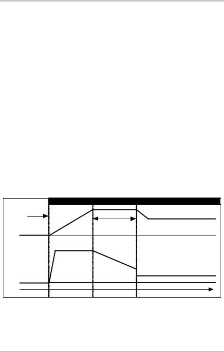
Three-Stage Battery Charging
The three-stage charging process results in faster charging compared to on-off relay type or constant voltage solid-state regulators. Faster recharging increases the performance of the system by storing more of the PV array’s limited output. The final float voltage setting reduces battery gassing, minimizes watering requirements and ensures complete battery recharging. The C-Series will use this protocol in either PV Charge Control mode or in Diversion Control mode. It does not charge the batteries when in Load Control mode. Battery voltage and current vary during the three-stage charging process as follows.
4 |
975-0004-01-02 Rev D |
Operating Modes
Bulk Stage
During this stage, the batteries are charged at the bulk voltage setting and maximum current output of the DC source. When the battery voltage reaches the bulk voltage setting, the controller activates the next stage (absorption).
Absorption Stage
During this stage, the voltage of the battery is held at the bulk voltage setting until an internal timer has accumulated one hour. Current gradually declines as the battery capacity is reached.
Float Stage
During this stage, the voltage of the battery is held at the float voltage setting. Full current can be provided to the loads connected to the battery during the float stage from the PV array. When battery voltage drops below the float setting for a cumulative period of one hour, a new bulk cycle will be triggered.
|
|
Bulk Stage |
Absorption Stage |
Float Stage |
Charging |
|
|
Bulk Volts Setting |
|
Started |
|
|
|
|
|
|
|
Absorption Time |
Float Volts Setting |
DC Voltage |
Increasing Voltage |
Constant Voltage |
Reduced Voltage |
|
0 volts |
|
|
|
|
|
|
Max Amps |
|
|
DC Current |
Constant Current |
Reducing Current |
Reduced Current |
|
0 amps |
|
|
|
|
Time |
|
|
|
|
Figure 1-2 |
3-stage Battery Charging Process |
|
||
975-0004-01-02 Rev D |
5 |

Introduction
Battery Temperature Compensation
The optional Battery Temperature Sensor (BTS) automatically adjusts the charging process of the C-Series controller. With the BTS installed, the C-Series will increase or decrease the battery charging voltage depending on the temperature of the battery to optimize the charge to the battery and maintain optimal performance of the battery.
If not using the BTS, the voltage settings for charging will need to be adjusted based on the temperature of the environment around the batteries and on the type of batteries being used.
See “Temperature Compensation” on page 33 for information on how to set the voltage.
Manual or Auto Equalization Charge
The C-Series controller can be used to manually or automatically provide the battery bank with an equalize charge. Factory default setting is for MANUAL Equalization charging. Be sure to be familiar with all the cautions and warnings concerning equalization charging batteries or damage to batteries can occur.
Load Control Mode
In the Load Control mode, the C-Series controls when to remove a load or loads from the system when an over-discharge or over-load situation occurs. The C-Series controller uses the user-adjustable setpoints to determine when to connect or reconnect loads depending on battery voltage. A load controller prevents damage to the battery from over-discharge during periods of poor weather or excessive loads. The unit does not charge the batteries when in this function.
6 |
975-0004-01-02 Rev D |
Controller Functions
Controller Functions
The C-Series can be configured to function as three different controllers:
•PV Charge Controller (Charge Control mode)
•Diversion Controller (Charge Control mode)
•Load Controller (Load Control mode)
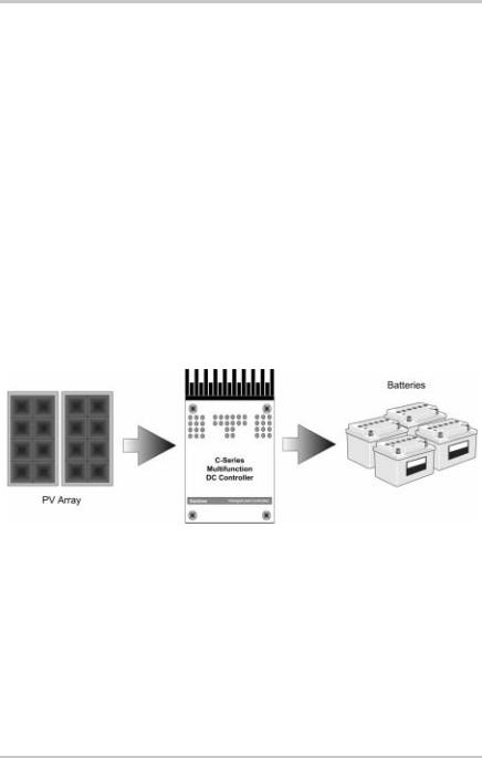
Photovoltaic Charge Controller
The C-Series controller can operate as a Photovoltaic Charge Controller, also called a “series regulator”. Depending on the model, the controller can regulate up to 60 amps of continuous photovoltaic (PV) array current at 12 or 24 volts (C60 or C35 models), or 12-, 24or 48-volts DC (C40 model) for charging batteries. This rating includes the NEC required derating.
Figure 1-3 PV Charge Controller
If the PV array’s output increases above the rated amp level due to reflection or “edge of cloud effect,” the controller will continue to operate until the heatsink reaches a maximum safe operating temperature. This will take several minutes to occur, depending upon the ambient temperature involved. When the heatsink reaches the maximum safe temperature, the controller will reduce the current, cooling the transistors and the heatsink.
975-0004-01-02 Rev D |
7 |

Introduction
If the current from the PV array reaches 85 amps, the controller will turn off to protect the circuitry. In the event of a shutdown, the controller automatically resets itself after 10 minutes (if overcurrent condition is no longer present).
See “Operating Mode Jumper” on page 20 for information on configuring this function.
Automatic PV Array Night Disconnect
When using PV Charge Control mode, the PV array is automatically disconnected from the battery at night to prevent reverse leakage of power. This eliminates the need for a blocking diode between the battery and the PV array. If thin-film or amorphous solar modules are being used, diodes may still be required to prevent damage from partial shading conditions.
Check the documentation provided with the PV modules.
Diversion Controller
The C-Series controller can operate as a Diversion Controller, also called a shunt regulator, to manage battery charging from alternative energy sources such as PV, wind or hydroelectric generators. A diversion controller monitors battery voltage and, when the voltage exceeds the settings for your charge stage (whether bulk or float), the power is diverted from the source (solar, wind, or hydro generator) to a “dump” load which will dissipate the excess power into heat.
When used for this purpose, the C-Series controller varies an amount of battery voltage to a “dump load” in order to redirect the excess power generated from over-charging the batteries. This allows the charging source to remain under constant load to prevent an over-speed condition which could occur if the charging source is suddenly disconnected from the battery–as series regulators do.
Consult your dealer for recommendations on diversion load type and regulator size.
8 |
975-0004-01-02 Rev D |
Controller Functions
Figure 1-4 Diversion Controller
Diversion Loads
Diversion control requires a separate “dump” load to regulate the battery. This load must be able to absorb more power than the charging source is able to produce at its peak output, or the DC voltage will become unregulated. The dump load must be available for the diversion of power at all times.
Resistive-type heating elements are the best diversion loads. Special direct-current water heating elements are available. Light bulbs and motors are not recommended as diversion loads because they are unreliable. A diversion load that draws about 25% more current than the charging source’s maximum output capability is usually suitable for use with the C-Series controller.
See Appendix C, “Diversion Loads” for additional information on types of diversion loads.
See “Operating Mode Jumper” on page 20 for instructions on enabling this mode.
975-0004-01-02 Rev D |
9 |

Introduction
Important: If PV arrays are used with diversion control, it may be necessary to install diodes to prevent night-time back-feed. If in doubt, contact or consult with your local renewable energy expert.
Important: If using multiple RE sources, use diodes/isolation to prevent backfeed.
CAUTION: Damage to Batteries
Current draw of the diversion load is very important. Problems may arise from operating with a load that is too small or too large. A diversion load that is too small will not be able to absorb all the excess power from the current source once the batteries are full allowing batteries to overcharge.
Diversion loads in excess of the controller’s rating are capable of absorbing more power than the C-Series controller is designed to handle, resulting in an over-current shut down. During this time, the unit will not regulate electrical flow in the system and battery damage may result.
Load Controller
The C-Series controller can operate as a Low Voltage Disconnect (LVD) for DC loads to prevent over-discharge to batteries during periods of poor charging or excessive loads. The C-Series controller uses the user-adjustable setpoints to determine when to disconnect or reconnect loads depending on battery voltage.
When used as a DC load controller, the settings of the LVR and LVD are controlled by two rotary potentiometers (also called pots) on the circuit board.
The scale on the adjustment potentiometers differ from the scale used for other functions. A decal with the appropriate adjustment scale is included with the C-Series. To apply the decal, gently pull off the knobs of the potentiometers and place this decal on the circuit board. After the decal is in place, replace the knobs. The EQ jumper determines manual
10 |
975-0004-01-02 Rev D |
Loading...