


INSTALLATION INSTRUCTIONS
MODEL PA4100X
FOUR CHANNEL HI-POWER AMPLIFIER
TABLE OF CONTENTS |
|
SectionTitle |
Page |
SAFETY INSTRUCTIONS - READ BEFORE OPERATING EQUIPMENT......................................................................................................... |
2 |
GENERAL INFORMATION ............................................................................................................................................................................. |
3 |
PA4100X PANEL AND FEATURE DESCRIPTIONS ........................................................................................................................................ |
5 |
INSTALLATION - PHYSICAL LOCATION AND MOUNTING ............................................................................................................................ |
8 |
CONNECTING THE PA4100X......................................................................................................................................................................... |
9 |
Stereo Mode Connections ...................................................................................................................................... |
9 |
Speaker Phasing.................................................................................................................................................. |
10 |
Connecting the REMOTE MASTER ON/OFF MUTE CONTROL........................................................................... |
10 |
A Multi-Zone System Diagram Using The PA4100X and MRC88.......................................................................... |
12 |
TROUBLE SHOOTING ................................................................................................................................................................................. |
13 |
SPECIFICATIONS ........................................................................................................................................................................................ |
14 |

Page 2 |
Model PA4100X |
SAFETY INSTRUCTIONS - READ BEFORE OPERATING EQUIPMENT
CAUTION: TO REDUCE THE RISK OF ELECTRIC SHOCK,
DO NOT REMOVE COVER (OR BACK)
NO USER-SERVICEABLE PARTS INSIDE
REFER SERVICING TO QUALIFIED SERVICE PERSONNEL
WARNING: TO MINIMIZE THE CHANCE OF ELECTRICAL SHOCK,
DO NOT OPERATE THIS PRODUCT WITHOUT HAVING SPEAKER
CONNECTORS PLUGGED-IN
The lightning flash with arrowhead symbol, within an equilateral triangle, is intended to alert the user to the presence of un-insulated “dangerous voltage” within the product’s enclosure that may be of sufficient magnitude to constitute a risk of electric shock to persons.
The exclamation point within an equilateral triangle is intended to alert the user to the presence of important operating and maintenance (servicing) instructions in the literature accompanying the appliance.
WARNING TO REDUCE THE RISK OF FIRE OR ELECTRIC SHOCK, DO
NOT EXPOSE THIS APPLIANCE TO RAIN OR MOISTURE.
This product was designed and manufactured to meet strict quality and safety standards. There are, however, some installation and operation precautions, which you should be particularly aware of.
1.Read Instructions – All the safety and operating instructions should be read before the appliance is operated.
2.Retain Instructions – The safety and operating instructions should be retained for future reference.
3.Heed Warnings – All warnings on the appliance and in the operating instructions should be adhered to.
4.Follow Instructions – All operating and use instructions should be followed.
5.Water and Moisture – The appliance should not be used near water – for example, near a bathtub, washbowl, kitchen sink, laundry tub, in a wet basement, or near a swimming pool, etc.
6.Carts and Stands – The appliance should be used only with a cart or stand that is recommended by the manufacturer. An appliance and cart combination should be moved with care. Quick stops, excessive force, and uneven surfaces may cause the appliance and cart combination to overturn.
7.Wall or Ceiling Mounting – The appliance should be mounted to a wall or ceiling only as recommended by the manufacturer.
8.Ventilation – The appliance should be situated so that its location or position does not interfere with its proper ventilation. For example, the appliance should not be situated on a bed, sofa, rug, or similar surface that may block the ventilation openings; or, placed in a built-in installation, such as a bookcase or cabinet that may impede the flow of air through the ventilation openings.
9.Heat – The appliance should be situated away from heat sources such as radiators, heat registers, stoves, or other appliances (including amplifiers) that produce heat.
10.Power Sources – The appliance should be connected to a power supply only of the type described in the operating instructions or as marked on the appliance.
11.Grounding or Polarization – Precautions should be taken so that the grounding or polarization means of an appliance is not defeated.
12.Power-Cord Protection – Powersupply cords should be routed so that they are not likely to be walked on or pinched by items placed upon or against them, paying particular attention to cords at plugs, convenience receptacles, and the point where they exit from the appliance.
13.Cleaning – The appliance should be cleaned only as recommended by the manufacturer.
14.Power Lines – An outdoor antenna should be located away from the power lines.
15.Nonuse Periods – The power cord of the appliance should be unplugged from the outlet when left unused for a long period of time.
16.Object and Liquid Entry – Care should be taken so that objects do not fall and liquids are not spilled into the enclosure through openings.
17.Damage Requiring Service – The appliance should be serviced by qualified service personnel when:
A.The Power-supply cord or the plug has been damaged; or
B.Objects have fallen, or liquid has spilled into the appliance; or
C.The appliance has been exposed to rain; or
D.The appliance does not appear to operate normally or exhibits a marked change in performance; or
E.The appliance has been dropped, or the enclosure damaged.
18.Servicing – The user should not attempt to service the appliance beyond that described in the operating instructions. All other servicing should be referred to qualified service personnel.
©2003 Xantech Corporation
Model PA4100X |
Page 3 |
GENERAL INFORMATION
To enhance the ease of installation and obtain optimum performance from the PA4100X, we recommend that you first become familiar with all its features and special capabilities by studying the descriptions and instructions in this manual.
The PA4100X was designed to meet the audio power amplifier needs of custom installed multi-zoned systems with high sonic quality and hi power output. It is a 4 Channel amplifier that is primarily intended to interface with the MRC88 Whole-house Audio Video Entertainment System for Zones 7 and 8 Preamp outputs or for Sub-Zone amplification of zones 1-6. It may also be used as a standalone 2-zone amplifier. Specific features and technology are as follows:
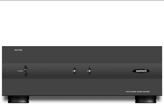
Figure 1: The Model PA4100X Amplifier
Cost/Size Efficiency. The PA4100X features four 100-watt power amplifiers. This permits each PA4100X to drive 2- zones in a multi-zone system -- each with a 100-watt stereo amplifier per zone.
Remote ON/OFF Control Jacks (C1 & C2). These 3.5mm Stereo Mini Jacks allow the PA4100X to be powered on and off and muted by a positive DC voltage ranging between 5 and 30 volts (11mA @ 12 V). Specifically, when interfaced with the Control Out jacks of zones 7 & 8 on the MRC88 (labeled CO1 and CO2), it permits the MRC88 to power the PA4100X ON and OFF automatically with zone ON/OFF commands or any 12VDC control signal.
Input Level Flexibility. The input level (sensitivity range) is individually adjustable (per stereo pair) from a low of 0.2 volts up to 3 volts. This gives the installer the ability to adjust the overall gain of the system or zone. For instance, there may be a need to adjust the amplifier to deliver a controlled, maximum sound level into a zone when the volume control on the preamp is set to maximum. This would act as a volume limiter for any particular zone (i.e. to prevent the kids from over-driving wall speakers, etc.).
Low Impedance Capability. Each amplifier is 4-Ohm safe under music conditions. This means, for instance, that you can drive two pairs of 8-Ohm speakers in stereo mode in each zone with ease.
Peak/Clip LED Indication: Whenever either amplifier channel output starts to enter a clipping state, the channels front panel LED will illuminate RED. After the amp stops clipping the LED will return to its normal state 5-6 seconds after clipping stops.
© 2003 Xantech Corporation
Page 4 |
Model PA4100X |
Auto Protection Circuit. This feature protects the PA4100X if a short or very low impedance is detected at the speaker terminals with each amplifier pair protected separately. Normal operation is restored automatically within 3 to 4 seconds after the short is removed.
© 2003 Xantech Corporation
Model PA4100X |
Page 5 |
PA4100X PANEL AND FEATURE DESCRIPTIONS
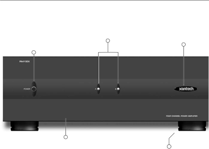
1.Front Panel. 17" X 5.25” panel designed for shelf mounting. The unit measures 6” high with the Feet (Item #5). When rack mounting use an adequate rack shelf mount making sure to allow for proper ventilation.
3
4
2
1
5
FIGURE 2 – THE MODEL PA4100X FRONT PANEL – FEATURES AND FUNCTIONS
2.POWER ON/OFF/STANDBY SWITCH:
POWER ON/OFF MODE: When the CI switch on the rear of the unit is set to OFF the front Power Switch will act as a standard ON/OFF (IN/OUT) control.
STANDBY MODE: With the POWER SWITCH left in the IN position (and the CI switch set to ON) the 2 channels of PA4100X may be controlled remotely from the MRC88 via the CI1 and CI2 Control Inputs (or any Voltage Control Signal). When both channels enter STANDBY Mode the front LEDS will turn off leaving the amplifier in a low current sleep mode.
3.Status LED Indicators. These indicators, one for each channel pair, provide the following status information:
GREEN LED: Indicates Amplifier is ON
RED LED: Indicates associated channel output is in a CLIPPING state. LED will go back to GREEN 5-6 seconds after clipping subsides.
ALL LED’s OFF: Indicates both amplifier channels are OFF or in STANBY MODE (see Item #4 for STANDBY MODE)
4.Illuminated LOGO: This is a backlit logo. When lit it indicates that the amplifier is powered ON. If the individual STATUS LED’s (Item #3) are OFF but the LOGO is ON, this indicates that both amplifier channels
©2003 Xantech Corporation
 Loading...