


INSTALLATION INSTRUCTIONS
PA1235
2 CHANNEL POWER AMPLIFIER
1 |
2 |
3 |
4 |
5 |
6 |
POWER
PA1235 12 CHANNEL POWER AMPLIFIER
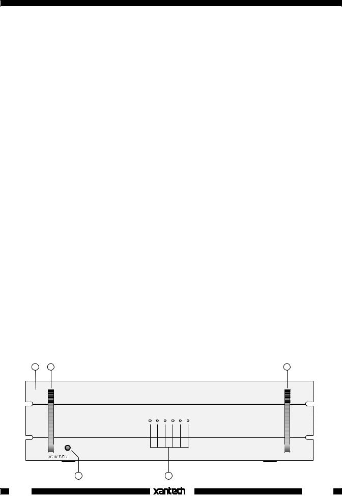
Fig. 1 The Model PA1235
GENERAL INFORMATION
To enhance the ease of installation and obtain optimum performance from the PA1235, we recommend that you first become familiar with all its features and special capabilities by studying the descriptions and instructions in this manual.
The PA1235 was designed to meet the audio power amplifier needs of custom installed multi-room, multizoned systems with high sonic quality. Common and Local IR control of Volume, Mute, Balance and OFF, for each channel pair, is provided. It's bridgeable 12-11-10-9-8-7-6 multichannel capability permits a wide variety of uses, such as enough channels to run surround sound home theater and multi-room applications simultaneously. Specific features and technology are as follows:
•Cost/Size Efficiency. The PA1235 features 12 conservatively rated 35-watt power amplifiers. This permits each PA1235 to drive 6-zones in a multi-zone system, each with a 35 watts/channel stereo amplifier per zone. The rack mountable low profile design, using a large single multiple filtered power supply, delivers high quality at a reasonable price.
•IR Controlled Volume Level. Volume can be ramped from zero output to maximum for individual channel pairs, or, as group through the Common Bus inputs, using IR volume control commands from an RC68+ (or RC68). The maximum input sensitivity at full volume is 0.15 volts for rated output (35 Watts/chan.).
•Local or Common Bus. Each stereo pair can be fed audio individually via their LOCAL inputs from differing zones or sources. In addition, a single source can be fed, via the COMMON Bus, to some or all stereo pairs as desired. This flexibility permits the installer to drive as many as six rooms in stereo as a single zone system, or six rooms in stereo as a six zone system --- or divide them up for a combination of both.
•Volume Setting Capabilities. The installer has the option of using the volume control of the PA1235 as the sole volume control for a zone or the system, or to adjust the PA1235 volume to a desired fixed level and use the volume action of a connected preamp instead.
•Max-V Setting. This allows the amplifier to be set to deliver a controlled maximum sound level into a zone when the volume is ramped to maximum. This acts as a volume limiter for the system (e.g. to prevent the kids from over-driving wall speakers, etc.).
® |
1 |
|
& Amplifiers
Preamplifiers
•12-11-10-9-8-7-6 Output Flexibility. Each of the 12 amplifiers can be driven singly or bridged to allow several channel and power output capabilities. It can be configured into seven power packages as follows:
-Twelve 35-watt amplifiers - 12 total.
-One 150 and ten 35-watt amplifiers - 11 total.
-Two 150 and eight 35-watt amplifiers - 10 total.
-Three 150 and six 35-watt amplifiers - 9 total.
-Four 150 and four 35-watt amplifiers - 8 total.
-Five 150 and two 35-watt amplifiers - 7 total.
-Six 150-Watt amplifiers - 6 total.
This gives the PA1235 great flexibility for use in many applications, such as driving surround sound speaker systems, in addition to multi-room.
•Individual ON/OFF of Amp Pairs. Permits Standby ON/OFF control of individual channel pairs. Specifically, it permits the STATUS outputs (12 Volts On/Off) of Xantech ZPR68 zones to switch the Standby of the PA1235 channel pairs (CI) On and Off with zone ON and OFF commands.
•Remote Master ON/OFF. Allows the entire PA1235 to be powered ON and OFF by a positive DC voltage ranging between 5 and 30 volts (16mA @ 12V). Specifically, it permits the 12 Volt common CO (Control Output) on the Xantech ZPR68 to power one or more PA1235's ON and OFF automatically with first zone ON and last zone OFF commands.
•Default settings. As received from the factory, Volume level is set to 1 Volt for 35 Watts output, Balance is centered and Mute is OFF, for all channels. Also, pressing the LEVEL (System) RESET switch 2 times within 1 second, restores all factory defaults. The PA1235 will always return to last set values (volume, etc.) after main power shut down or after any power interruptions.
•Low Impedance Capability. Each amplifier is 4-Ohm safe under music conditions in stereo mode and 8-Ohm safe when bridged. This means, for instance, that you can drive two pairs of 8-Ohm speakers in stereo mode in each zone.
PA1235 PANEL AND FEATURE DESCRIPTIONS
1.Front Panel. 19" x 5-1/4" panel designed for mounting into a standard 19" Rack Panel.
2.Rack Panel Handles.
3.POWER Switch. When pressed to the IN position, power is applied to the PA1235 [provided the rear panel master AC LINE ON/OFF Switch, item 17, is placed in the ON (I) position]. This is the MANUAL ON position. When pressed again, it releases to the OUT position (MANUAL OFF), turning the unit OFF.
1 |
2 |
2 |
1 |
2 |
3 |
4 |
5 |
6 |
|
POWER |
|
|
|
|
|
|
|
|
|
|
|
|
PA1235 12 CHANNEL POWER AMPLIFIER |
3 |
|
|
4 |
|
|
Fig. 2 PA1235 Front Panel – Features and Functions |
2 |
|
|
|
|
® |
|
|
|
|
|
|
PA1235 |

In addition, this switch must be left in the MANUAL OFF (OUT) position to permit an external DC Control Voltage to power the PA1235 ON and OFF.
Refer to "REMOTE MASTER ON/OFF CONTROL" terminals, item #13.
NOTE: The PA1235 may also be powered ON/OFF with an external AC line switch into which the power cord of the PA1235 is plugged (such as the switched AC outlet of a preamp, timer, etc.).
For this type of operation, leave the POWER switch depressed to the MANUAL ON position.
4.Status LED Indicators. These indicators, one for each channel pair, provide the following status information:
a)They show Power ON/OFF and Standby ON/OFF conditions.
b)They flash Amber 5 times during power up, then turn steady Green when Power On Mute releases. On power down, they flash Amber once, then go off.
This action occurs whether the unit is powered ON and OFF by the POWER switch (item # 3) or by a DC voltage applied to the REMOTE MASTER ON/OFF CONTROL terminals (item #13). Be sure the rear panel master AC LINE ON/OFF Switch, item #17, is set to the ON (I) position for the above to occur.
c)They will go Off when the Standby OFF IR command is received. Sending a MUTE OFF command will restore operation. Also, LEDs blink with Volume action.
d)A Mute command will cause them to blink Green (Red if Volume is within 5 dB of Max-V). Mute is released when any other PA1235 command is sent.
e)Changing an IR Code Group will cause them to blink Amber, confirming the change has taken effect.
f)When the volume level is increased to a range within 5 dB of MAX-V, the LED color changes from Green to Red. NOTE: Red indicates that volume is approaching maximum --- not an indication of power output level.
5.Line Inputs. These RCA-type jacks are the audio inputs for each of the amplifier pairs. Connect them to the OUTPUT jacks of the driving preamp with good quality RCA-type patch cables. Note that the inputs are marked LEFT-1-RIGHT, LEFT-2-RIGHT, etc., signifying the stereo channel pairs. Both the LEFT and RIGHT jacks are also active when the MODE switch (item #7) is set to the MONO or BRIDGED mode.
6.COMMON BUS / LOCAL Switch. Switches the amplifier stereo pair inputs between the LOCAL (LEFT/RIGHT) jacks, item #5 and the COMMON AUDIO BUS (LEFT/RIGHT) jacks, item #8. In this way, each amplifier pair can be driven by separate zones or sources or from a common source via the COMMON AUDIO BUS.
7.MODE Switch. Switches the amplifier pair between STEREO, MONO and BRIDGED modes.
In STEREO mode, the two amplifiers operate independently of each other for 35 Watts of output each, except IR control of Volume, Max-V, Mute, Standby OFF/ON and Balance functions is common to both.
In MONO mode, left and right input signals are summed internally for Mono output from each of the two amplifiers. Also, either the Left or Right (item #5) input may be used if the source is already a Mono signal.
In BRIDGED mode, the two amplifiers are bridged for a single channel of high power output (150 Watts @ 8 Ohms). Either the Left or Right input (item #5) may be used to drive the resultant single channel amplifier.
CAUTION: Be sure to have the POWER turned OFF when changing the position of this switch and when making the corresponding speaker connection changes (see also item #12, following).
|
|
|
® |
|
|
|
|
PA1235 |
|
|
3 |
|
|
|
|
|
|
|||
|
|
|
|
|
|
|
|
|
|
|
|
|
|
& Amplifiers
Preamplifiers

|
|
|
|
|
|
|
|
|
|
|
8 |
9 |
|
|
|
|
|
10 |
5 |
6 |
7 |
5 |
6 |
7 |
5 |
6 |
7 |
5 |
6 |
7 |
|
5 |
6 |
7 |
5 |
6 |
7 |
|
COMMON BUS |
|
|
COMMON BUS |
|
|
COMMON BUS |
|
|
COMMON BUS |
|
|
|
COMMON BUS |
|
|
COMMON BUS |
® |
|
|
|
|
|
|
|
|
|
|
|
|
|
|
|
|
|
|
|
|
|
|
|
|
|
|
|
|
|
|
|
|
|
|
|
|
|
SYLMAR, CA |
LEFT |
LOCAL |
RIGHT |
|
LEFT |
LOCAL |
RIGHT |
|
|
LEFT |
LOCAL |
RIGHT |
|
LEFT |
LOCAL |
RIGHT |
COMMON AUDIO |
LEFT |
LOCAL |
RIGHT |
|
LEFT |
LOCAL |
RIGHT |
AC 120V 60 HZ |
|||||||||
|
|
1 |
|
|
|
|
2 |
|
|
|
|
|
3 |
|
|
|
|
4 |
|
|
|
BUS |
|
|
|
5 |
|
|
|
|
6 |
|
4 AMP |
|
|
STEREO |
WARNING |
|
STEREO |
CAUTION |
|
STEREO |
WARNING |
|
STEREO |
|
|
|
|
|
STEREO |
WARNING |
|
STEREO |
FUSE |
||||||||||||
|
|
|
|
|
|
|
|
|
|
|
10 AMP |
||||||||||||||||||||||
MODE |
|
MONO |
TURN POWER |
MODE |
|
MONO |
RISK OF ELECTRIC |
MODE |
|
MONO |
TURN POWER |
MODE |
|
MONO |
|
|
|
|
MODE |
|
MONO |
TURN POWER |
MODE |
|
MONO |
SLOW BLOW |
|||||||
|
BRIDGED |
|
BRIDGED |
SHOCK. DO NOT OPEN |
|
BRIDGED |
|
BRIDGED |
LEFT |
|
RIGHT |
|
BRIDGED |
|
BRIDGED |
|
|||||||||||||||||
|
|
|
|
OFF BEFORE |
|
|
|
|
|
|
|
|
|
|
OFF BEFORE |
|
|
|
|
|
|
|
|
|
|
|
|
OFF BEFORE |
|
|
|
|
|
CI |
GROUND |
STATUS |
INIR |
CHANGING |
CI |
GROUND |
STATUS |
INIR |
ON/OFF |
CONTROL |
CI |
GROUND |
STATAUS |
INIR |
CHANGING |
CI |
GROUND |
STATUS |
INIR |
|
LEVEL |
|
CI |
GROUND |
STATUS |
INIR |
CHANGING |
CI |
GROUND |
STATUS |
INIR |
|
|
MODES |
MODES |
|
|
MODES |
|
||||||||||||||||||||||||||||
|
|
|
|
|
|
|
|
|
REMOTE MASTER |
|
|
|
|
|
|
|
|
|
|
RESET |
|
|
|
|
|
|
|
|
|
|
|
||
|
|
|
|
|
|
|
|
|
|
|
|
|
|
|
|
|
|
|
|
N/C |
GROUND |
STATUS |
IR IN |
|
|
|
|
|
|
|
|
|
|
+ |
BRIDGED -- |
|
+ |
BRIDGED -- |
-- |
+ |
+ |
BRIDGED -- |
|
+ |
BRIDGED -- |
|
|
|
|
+ |
BRIDGED -- |
|
+ |
BRIDGED -- |
|
||||||||||||
SPEAKER |
|
|
SPEAKER |
|
SPEAKER |
|
|
SPEAKER |
|
|
|
|
|
SPEAKER |
|
|
SPEAKER |
|
|
||||||||||||||
|
|
|
5-30 VOLTS DC |
|
|
|
|
|
|
|
|
|
|
|
|||||||||||||||||||
LEFT |
-- |
RIGHT |
|
LEFT |
-- |
RIGHT |
|
|
LEFT |
-- |
RIGHT |
|
LEFT |
-- |
RIGHT |
|
|
|
|
LEFT |
-- |
RIGHT |
|
LEFT |
-- |
RIGHT |
AC LINE |
||||||
+ |
-- |
+ |
|
+ |
-- |
+ |
|
|
+ |
-- |
+ |
|
+ |
-- |
+ |
|
|
|
|
+ |
-- |
+ |
|
+ |
-- |
+ |
ON/OFF |
||||||
-- 0
0
11 |
12 |
11 |
12 |
|
11 |
12 |
11 |
12 |
|
11 |
12 |
11 |
12 |
|
|
|
|
13 |
14 |
|
|
|
15 |
16 |
|
|
|
17 |
18 |
Fig. 3 PA1235 Rear Panel – Features and Functions
8.COMMON AUDIO BUS. A single audio source, such as from a connected preamp, can drive one or more of the amplifier pairs simultaneously, as desired, from this Bus. Any of the amplifier pairs can be switched to the COMMON AUDIO BUS at will by use of the COMMON BUS / LOCAL Switch (see also item #6).
9.LEVEL (System) RESET Button. Pressing this button 2 times within 1 second restores all Factory Default settings. The Factory Defaults for all channels are as follows:
-Input Level set to 1 Volt rms for 35 Watts output.
-Balance centered.
-Mute OFF.
-MAX-V Cleared.
-IR Code Group set to A0.
-CI (control in) disabled. Chantes CI control to IR control of Standby ON/OFF. (CI enables when +5 to +30 VDC is applied to CI for 2 or more seconds. See also item #11)
NOTE: The PA1235 will always return to last set values (plus any unaltered factory defaults) after main power shut down or after any power interruptions.
10.FUSE. When required, replace only with a fuse of the same type and rating:
120 V Version: 10 AMP 220 VAC, SLOW BLOW.
240 V Version: 5 A Time-Lag 250 VAC.
Replacement with a fuse of higher rating will not protect the amplifier and will void the warranty.
11.IR IN, STATUS, GROUND and CI Terminals. Removable 4-Terminal screw type plug-in connector.
IR IN = IR Signal. Receives IR Input from Xantech IR Receivers, Smart Pads, Connecting Blocks, etc.
STATUS Out. Delivers a constant +12 VDC output (9V @ 70 mA) with ON condition. 0 Volts output = OFF (Standby).
GROUND. Ground for IR IN, STATUS out & CI in.
CI = Control Input. Use for control of Standby ON/OFF of amplifier pairs, if desired, instead of by IR. After CI is enabled (see item #9), 0 Volts input = OFF (Standby) condition and +5 to +30 VDC input = ON condition. (12V in draws 16 mA).
NOTE: All plug-in connectors accept wire sizes from 24 to 12 gauge.
|
|
|
® |
|
|
|
|
4 |
|
|
|
|
|
|
|
|
PA1235 |
|
||
|
|
|
|
|||
|
|
|
|
|
|
|
|
|
|
|
|
|
|

12.SPEAKER Terminals. These plug-in 4-terminal screw type connectors permit speaker wire sizes up to 12 gauge. When making connections for the STEREO mode, be sure to observe the "+" and "–" polarity markings, just under the LEFT & RIGHT markings, for each wire pair going to the speakers.
CAUTION: When making connections for the BRIDGED mode, remember, only one speaker is being attached per amplifier pair. Be sure to observe the outer "+" and "–" polarity markings on each side of the word "BRIDGED" on the panel above the 4-terminal connector when connecting the 2-conductor wire to the speaker.
13.REMOTE MASTER ON/OFF CONTROL. This 2-terminal connector allows the entire PA1235 to be powered ON and OFF by a control voltage ranging between 5 and 30 Volts DC (16mA @ 12 V). Be sure to observe the marked polarity. For instance, the 12 volt common CO (Control Output) of the Xantech ZPR68 preamp will power the PA1235 ON and OFF automatically with the first zone ON and last zone OFF commands.
The DC Voltage must be applied continuously to retain the ON condition and drop to less than 0.5 Volt to switch to the OFF condition.
NOTE: The front panel POWER switch (item #3) must be left in the Manual OFF (Out) position and the Master AC Line Switch (item #17) set to ON (I) to permit the REMOTE MASTER ON/OFF CONTROL to operate.
See also CAUTION notes, Fig. 9.
14.Rear Panel ON/OFF LED. This LED indicates the power ON/OFF condition of the entire PA1235, whether activated by a REMOTE MASTER ON/OFF CONTROL voltage (item #13) or from the front panel POWER switch (item # 3).
15.Common IR IN and STATUS Connector. This 4-terminal connector provides the same type of IR control functions as that of the individual amplifier pairs (item #11) except they apply to all amplifier pairs in common. That is, IR commands for Volume, Mute, etc., control all amplifier pairs together.
NOTE: Individual control of amplifier pairs is possible, however, through the Common IR IN, provided the IR Code Group is changed on amplifier pairs you wish to control separately.
The STATUS output goes high and low with the AC Power ON/OFF state of the entire PA1235. It does not respond to a Common IR OFF/ON (Standby) condition.
16.Grounding Screw. Provides a means for chassis connection to earth ground or to other A/V products to aid in the reduction of system noise, etc., where needed.
17.Master AC LINE ON/OFF Switch. Turns power OFF to the entire PA1235, regardless of IR, Control IN, or front panel POWER switch conditions. Must be placed in the ON (I) position for the other power switching functions to work.
18.3-Conductor AC Line Cord Receptacle. Standard IEC male receptacle for plug-in of a 3-conductor power line cord. Depending on the application, plug the line cord into a switched or un-switched 120V 60 Hz AC outlet (or 240 VAC 50 Hz on the 240 V version).
RC68+ (or RC68) PROGRAMMER / REMOTE CONTROL
The RC68+ Programmer (available separately) contains all the commands necessary to operate the IR control functions of the PA1235.
•You will need it to program universal learning devices such as the Xantech URC-2 learning remote, the Xantech Smart Pads, the 590 Programmable Controller, the 710 Fone Link, etc., with commands that operate the PA1235.
•NOTE: The RC68+ codes operate many other Xantech models as well, such as the RGC11, CC12, ZPR68, etc. Therefore, only the button descriptions that apply to the operation of the PA1235 are listed below. All others should be ignored.
CAUTION: While the RC68+ can be used as a handheld remote control, it is highly recommended it not be given to the final user for the following reasons:
|
|
|
® |
|
|
|
|
PA1235 |
|
|
5 |
|
|
|
|
|
|
|||
|
|
|
|
|
|
|
|
|
|
|
|
|
|
& Amplifiers
Preamplifiers
 Loading...