


QUICK START GUIDE
MRC88
MRAUDIO8X8
EIGHT ZONE – EIGHT SOURCE
AUDIO & VIDEO CONTROLLER/AMPLIFIER SYSTEMS

MRC88 / MRAUDIO8X8 QUICK START GUIDE |
2 |
TABLE OF CONTENTS |
|
READ THIS FIRST!!!.......................................................................................................................................................... |
3 |
SYSTEM PLANNING ......................................................................................................................................................... |
5 |
CONTROLLER LOCATION........................................................................................................................................... |
5 |
MOUNTING THE KEYPAD............................................................................................................................................ |
6 |
Keypad Location ...................................................................................................................................................... |
6 |
KEYPAD CABLE LENGTH ........................................................................................................................................... |
7 |
SPEAKER WIRE LENGTH............................................................................................................................................ |
8 |
VIDEO MONITOR CABLE LENGTH (MRC88).............................................................................................................. |
9 |
PREPARATION – WIRING .............................................................................................................................................. |
10 |
TERMINATING THE CAT5 CABLES .......................................................................................................................... |
10 |
AC POWER.................................................................................................................................................................. |
11 |
GROUNING SCREW ................................................................................................................................................... |
11 |
SOURCE CONNECTIONS ............................................................................................................................................... |
12 |
MRAUDIO8X8 (Audio Only) ....................................................................................................................................... |
12 |
MRC88 (Audio/Video)................................................................................................................................................. |
12 |
IR EMITTERS............................................................................................................................................................... |
13 |
CONNECTIONS ............................................................................................................................................................... |
14 |
KEYPADS .................................................................................................................................................................... |
14 |
Head End Connections.......................................................................................................................................... |
14 |
Zone Connections.................................................................................................................................................. |
14 |
SPEAKERS.................................................................................................................................................................. |
15 |
Head End Connections.......................................................................................................................................... |
15 |
Zone Connections.................................................................................................................................................. |
15 |
VIDEO DISPLAY (MRC88) .......................................................................................................................................... |
16 |
Head End Connections.......................................................................................................................................... |
16 |
Zone Connections.................................................................................................................................................. |
16 |
SYSTEM INITIALIZATION ............................................................................................................................................... |
17 |
OUT-OF-BOX SYSTEM FUNCTIONALITY................................................................................................................. |
17 |
SYSTEM DEFAULT SETTINGS.................................................................................................................................. |
18 |
ZONE AUDIO ADJUSTMENTS (MRC88 Keypad – User Settings) .......................................................................... |
19 |
AUDIO ADJUSTMENTS (Z-Adjust – Installer Settings)........................................................................................... |
19 |
Trim ......................................................................................................................................................................... |
19 |
Zone Audio Adjustments ...................................................................................................................................... |
20 |
RESTORE SYSTEM DEFAULT SETTINGS................................................................................................................ |
21 |
PROGRAMMING – UNIVERSAL DRAGON .................................................................................................................... |
21 |
SOFTWARE INSTALLATION...................................................................................................................................... |
21 |
WHO AM I .................................................................................................................................................................... |
22 |
FIRMWARE UPGRADE OPTIONS.............................................................................................................................. |
23 |
Downloading Firmware Files From The Web ...................................................................................................... |
23 |
WARM FIRMWARE UPGRADE .................................................................................................................................. |
24 |
COLD FIRMWARE UPGRADE.................................................................................................................................... |
25 |
STARTING A NEW MRC88 PROJECT....................................................................................................................... |
26 |
CONFIGURING THE SOURCE ICONS .................................................................................................................. |
27 |
PROGRAMMING SOURCE IR COMMANDS ......................................................................................................... |
27 |
TEST IR COMMANDS............................................................................................................................................. |
29 |
PUNCH SYSTEM (Copy IR Programming to all Zones) ...................................................................................... |
30 |
TRANSFER THE PROJECT ................................................................................................................................... |
31 |
SAVING THE PROJECT ......................................................................................................................................... |
32 |
SAVE PROJECT AS ............................................................................................................................................... |
33 |
ADVANCED PROGRAMMING.................................................................................................................................... |
33 |
APPENDIX........................................................................................................................................................................ |
34 |
MRC88 CONTROLLER/AMPLIFIER PANEL FEATURE DESCRIPTIONS................................................................ |
34 |
MRC88 KEYPAD FEATURE DESCRIPTIONS ........................................................................................................... |
38 |
SPECIFICATIONS............................................................................................................................................................ |
41 |
08905142A

MRC88 / MRAUDIO8X8 QUICK START GUIDE |
3 |
READ THIS FIRST!!!
About the MRC88/MRAUDIO8X8 Quick Start Guide
The MRC88/MRAUDIO8X8 Quick Start Guide provides fundamental instruction for planning, installing, connecting and programming a basic MRC88 System. The MRC88 Series Controllers have features and options to accommodate functionality in the most basic or sophisticated of whole-house audio/video distribution and control applications. This Guide only provides instruction to the most basic application of a MRC88 System as used in a multi-zone audio/video system using standard MRC88 Keypads.
Advanced options such as integrating Xantech SPLCD Touchpanels (SPLCD64V, SPLCD64G, SPLCD39G), Music Server (XMUSICW+), Dual Tuner (XDT), HD video distribution (HD44CC5), doorbell and paging interface (DPC100, DCSS, DCCBB, DCH4), RS232 control and routing (RS2321X8), adding local sources (ZAKIT, ZATRAN, ZA8REC), sub-zone expansion and integration of high-power and multi-channel amplifiers (PA435X, PA635X, PA1235X, PA4100X) can all be implemented in a MRC88 System, but are not covered in this Guide. Please refer to the MRC88/MRAUDIO8X8 Installation Instructions or the appropriate individual Xantech product manuals for instructions on integrating those products.
Additionally, advanced programming instructions covering: macro programming, power management utilizing sensing modules and programming sensor triggers (SM Series Modules), RS232 control, zone linking, monitor lockout, and all other advanced programming options can be found in the MRC88/MRAUDIO8X8 Installation Instructions and/or individual Xantech product manuals.
Xantech Manuals can be downloaded from www.xantech.com .
The Xantech Technical Support Department is also available to assist in answering integration and programming questions at 1.800.843.5465 ext 335 or via email at tech@xantech.com .
08905142A

MRC88 / MRAUDIO8X8 QUICK START GUIDE |
4 |
Figure 1 – Typical MRC88 System
08905142A
MRC88 / MRAUDIO8X8 QUICK START GUIDE |
5 |
SYSTEM PLANNING
CONTROLLER LOCATION
Consider all of the flowing when planning the Controller location:
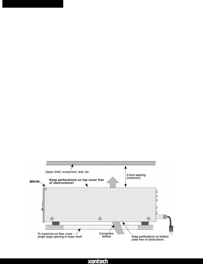
1.The MRC88 depends on the natural free flow of air up through the slot perforations in the bottom plate, over the internal heat dissipating fins, then out the top cover, for adequate cooling.
2.Provide large holes in the shelf below the MRC88 and allow at least 2 inches of space above the top cover to allow adequate airflow.
3.Never remove the chassis feet. They are required to create space for adequate airflow.
4.Pay close attention to the overall thermal conditions within a cabinet if other heat generating components are also being used.
5.Both MRC88 and MRAUDIO8X8 have built-in fans that will automatically turn on at a manufacturer specified temperature. Use of external fans, (quiet, boxer type) is recommended to provide constant airflow for the MRC88 and other heat generating components when appropriate.
6.When rack mounting, always use a single ventilated rack space panel above and below the MRC88.
7.The MRC88 is designed for horizontal mounting on flat surfaces. When rack mounting, use a proper rack shelf or drawer. (Middle Atlantic or equivalent.)
8.In multi-zone installations there will be large bundles of wire and cable to accommodate audio, video, speaker and control connections. Be sure to leave enough room for the leads and dress them in such a manner as to not block airflow.
Figure 2 – MRC88 Controller Installation
08905142A
MRC88 / MRAUDIO8X8 QUICK START GUIDE |
6 |
MOUNTING THE KEYPAD
Keypad Location
•The MRC88 Keypad should be mounted in a convenient location, typically near the entrance to a room where other room controls such as light switches are located.
NOTE: Some light dimmers can interfere with the Keypad and IR Sensor. Test compatibility prior to determining mounting location.
•Do not mount the Keypads in locations that will be exposed to sunlight or bright artificial light. Bright light sources can interfere with the IR Sensor on the Keypad, preventing use of remote controls. Cumulative light noise can interfere with system and source control from other zones as well.
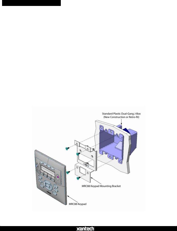
To mount the Keypad, use a plastic, dual-gang, new construction or retro fit J- box and the included MRC88 Keypad Mounting Bracket as shown in Figure 3. NOTE: Do not mount the Keypad in the same box with high voltage (AC) devices. This can interfere with system performance and is a violation of building/electrical code in most places.
Figure 3 – Installing the MRC88 Keypad
08905142A
MRC88 / MRAUDIO8X8 QUICK START GUIDE |
7 |
KEYPAD CABLE LENGTH
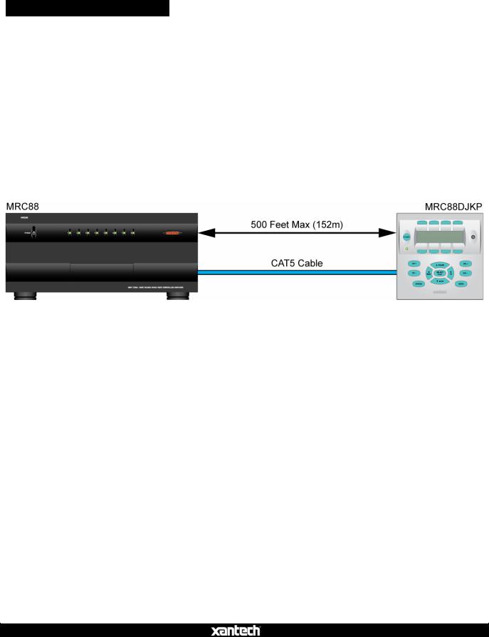
The maximum cable length for MRC88 connection to a single keypad is 500 feet (152m) over CAT5 cable.
•Zone Keypad CAT5 cables should be pulled in home-runs from the keypad locations to the MRC88 Controller.
•Label each end of the CAT5 with the Zone Number and Room Name to assure proper connection and assist in troubleshooting.
•CAT5 cable must be properly terminated with RJ45 connectors for MRC88 Keypad connections. See Sections: Preparation, (Page 10) and Zone Connections/ Keypads, (Page 14) in this Guide for additional information.
Figure 4 – MRC88 Keypad CAT5 Cable Length
NOTE: To connect additional MRC88 Keypads, WaterPads and IR Sensors, see: MRC88/MRAUDIO8X8 Installation Instructions/Extended Runs and Secondary Keypads in Zone, (Page 31). For connecting SPLCD Keypads see: SmartPad LCD Installation & Programming Manual/MRC Controller and Expansion Port Wiring, (Page 17).
08905142A
MRC88 / MRAUDIO8X8 QUICK START GUIDE |
8 |
SPEAKER WIRE LENGTH
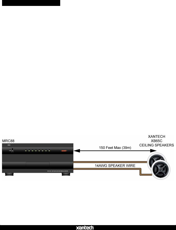
The maximum wire length for Zone Speaker connections is 150’ (39m) over 14AWG stranded wire.
•Speaker wire should be pulled in home-runs from the speaker locations to the MRC88 Controller, two pair for each zone.
•Always use quality stranded speaker wire for zone speaker connections.
•Label each end of the speaker wire with the Zone Number and Room Name to assure proper connection and assist in troubleshooting.
•MRC88 Speaker Terminals are 4-Ohm safe. Be sure the combined impedance presented to the speaker terminals by the speakers (or any combination of speakers) is greater than 4-Ohms.
Use the following Table to determine speaker wire gauge based upon the length of the speaker wire run:
|
Length of Speaker Wire Run |
|
|
Gauge of Wire |
|
|
|
|
|
|
|||
|
30’ |
(9m) |
|
|
18AWG |
|
|
70’ (21m) |
|
|
16AWG |
||
|
150’ |
(39m) |
|
|
14AWG |
|
Table 1 – Speaker Wire Length/Gauge
Figure 5 – MRC88 Zone Speaker Wire Length
08905142A
MRC88 / MRAUDIO8X8 QUICK START GUIDE |
9 |
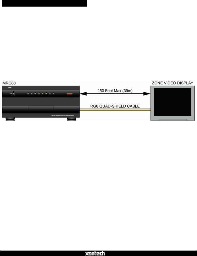
VIDEO DISPLAY CABLE LENGTH (MRC88)
The maximum coaxial cable length for Zone Video Output is 150’ over RG6 quad-shield cable.
•Coax for zone video should be pulled in home-runs from the zone video display locations to the MRC88.
•Coax must be properly terminated with a shielded male RCA video plug on the MRC88 end and as appropriate for connection to the video display. (Shielded male RCA plug typical)
•Label each end of the coax with the Zone Number and Room Name to assure proper connection and assist in troubleshooting.
Figure 6 – MRC88 Zone Video Cable Length
08905142A
MRC88 / MRAUDIO8X8 QUICK START GUIDE |
10 |
PREPARATION – WIRING
CAUTION: Power voltage for the keypad is transmitted along the CAT5 cable!
Incorrect wiring on this cable can destroy the MRC Keypad!
TERMINATING THE CAT5 CABLES
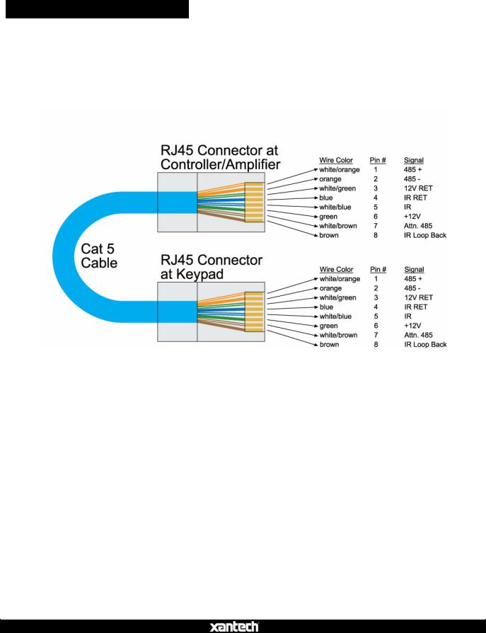
All MRC88 CAT5/RJ45 connections utilize the EIA/TIA 568B Standard pin-out as shown in Figure 7.
Figure 7 – CAT5/RJ45 Pin-out (EIA/TIA 568B)
Cables should be configured in a pass through (pin to pin) configuration. To terminate CAT5 cables:
1.Trim the end of the CAT5 so all eight conductors are the same length.
2.Using a CAT5 stripper, strip away approximately ½ inch of the cable jacket. DO NOT STRIP THE INDIVIDUAL WIRES. Strip only enough of the jacket to make connections. None of the individual wires should be hanging out the end of the RJ45 connector when finished. There must be sufficient jacket on the cable to allow the hinged tab on the RJ45 connector to apply pressure to the cable jacket to function as a strain relief when pressed together with the crimp tool.
3.With the RJ45 locking tab facing down, insert the individual wires into the RJ45 connector per EIA/TIA 568B Standard pin-out as shown in Figure 7.
4.Use a RJ45 crimping tool to press the electrical contacts into the individual wires and the hinged tab into place as the strain relief.
08905142A
MRC88 / MRAUDIO8X8 QUICK START GUIDE |
11 |
Test the cable connections using a proper CAT5 cable tester or use a multimeter to check pin to pin continuity and for possible shorts. Using either method, it is advisable to measure pins 3 and 6 to verify proper voltage. A 12VDC measurement should be read when the positive probe is on pin 6 and the negative probe is on pin 3. See Figure 7.
AC POWER
It is recommended, but not required, that the MRC88 Controller and head-end source components be powered by a dedicated 20-amp circuit with an isolated ground.
Whole-house system components turning on/off at various times (headend/common sources that may time out or local zone sources and amplifiers turning on/off), lighting systems and other household appliances, can introduce undesirable conditions (surges, ground hum, EMI, RFI, clicks and pops) on the AC line that can adversely affect overall system performance.
An AC line conditioner can also be incorporated to protect components from unstable AC and improve system performance by filtering AC line noise.
GROUNING SCREW
Connect to earth ground or other A/V components to aid in the reduction of system noise such as an audible hum created by the difference in ground potential between devices, if needed.
08905142A
MRC88 / MRAUDIO8X8 QUICK START GUIDE |
12 |
SOURCE CONNECTIONS
Be sure the MRC88 power is off and the unit is disconnected the from the AC supply when making connections to avoid potential electrical shock and damage to the MRC88, the Keypads, Sources and Speaker components.
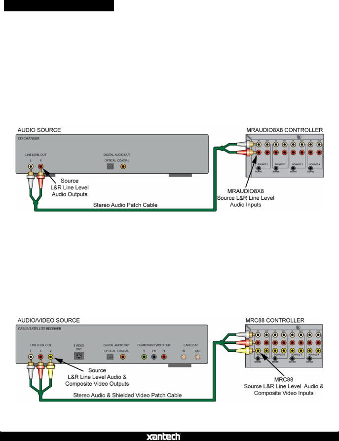
MRAUDIO8X8 (Audio Only)
1.Use a quality stereo audio patch cable to connect the L&R line level audio outputs of a source component to the appropriate L&R line level source audio inputs on the MRAUDIO8X8 rear panel.
2.Repeat for all sources.
Figure 8 – Audio Source Connections
MRC88 (Audio/Video)
1.Use quality stereo audio/video patch cables to connect the L&R line level audio and composite video outputs of a source component to the appropriate L&R line level source audio and composite video input on the MRC88 rear panel.
2.Repeat for all sources.
Figure 9 – Audio/Video Source Connections
08905142A

MRC88 / MRAUDIO8X8 QUICK START GUIDE |
13 |
IR EMITTERS
Use the 8 included 283M Emitters for IR control of common source components.
1.Locate the IR sensor on the device to be controlled. If the sensor is not obvious, shine a small flashlight into the device front panel display to locate the sensor or refer to the product manual for that device.
2.Remove the adhesive protective cover on the flat side of the emitter and attach the emitter over the IR sensor on the front panel of the source to be controlled via IR.
3.Carefully pull the emitter wire around to the back of the unit. Do not block disc and tape accesses. Do not pinch the wire between components.
4.Plug the emitter into the appropriate source IR Emitter Output on the MRC88 rear panel.
5.Repeat for all sources to be controlled via IR.
Figure 10 – IR Emitter Connection
08905142A
MRC88 / MRAUDIO8X8 QUICK START GUIDE |
14 |
ZONE CONNECTIONS
KEYPADS
Prior to connecting the keypads, be sure the zone dual-gang boxes and keypad mounting brackets have been installed and the keypad CAT5 runs have been terminated and tested as described in the previous sections.
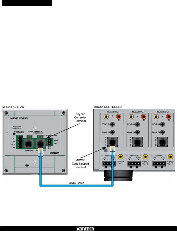
Head End Connections
1.Connect the zone CAT5 keypad cable to the appropriate Zone Keypad Terminal on the MRC88 rear panel. Be sure the RJ45 connector ‘clicks’ into place.
2.Repeat for all zones.
Zone Connections
1.Connect the zone CAT5 cable to the Controller Terminal on the MRC88 Keypad rear panel. Be sure the RJ45 connector ‘clicks’ into place.
2.Firmly snap the keypad into the Keypad Mounting Bracket. (Figure 3)
3.Repeat for all zones.
Figure 11 – Zone Keypad Connections
08905142A
 Loading...