


INSTALLATION INSTRUCTIONS
D5RH
DIGI-5 DDS Digital Distribution System
Rack Mount 4 Source, 4 Zone Hub
|
|
08905153B |
- 1 - |

Safety Information
CAUTION: TO REDUCE THE RISK OF ELECTRIC SHOCK, DO NOT
REMOVE COVER (OR BACK). NO USER SERVICEABLE PARTS
INSIDE.
REFER SERVICING TO QUALIFIED SERVICE PERSONNEL.
The lightning flash with arrowhead symbol within an equilateral triangle is intended to alert the user to the presence of uninsulated "dangerous voltage" within the product's enclosure that may be of sufficient magnitude to constitute a risk of electric shock to persons.
The exclamation point within an equilateral triangle is intended to alert the user to the presence of important operating and maintenance (servicing) instruction in the literature accompanying the appliance.
WARNING: TO REDUCE THE RISK OF FIRE OR SHOCK,
DO NOT EXPOSE THIS APPLIANCE TO RAIN OR MOISTURE.
IMPORTANT SAFETY INFORMATION
Read Information — All the safety and operating information should be read before the appliance is operated. Follow Information — All operating and use information should be followed.
Retain Information — The safety and operating information should be retained for future reference. Heed Warnings — All warnings on the appliance and in the operating instructions should be heeded. Wall Mounting — Mounting of this appliance should be done only by an authorized installer.
Ventilation — The appliances should be situated so that their location or position does not interfere with their proper ventilation. These appliances should never be placed near or over a radiator or heat register. These appliances should not be placed in a built-in installation such as a bookcase or cabinet that may impede the flow of air through the ventilation openings.
Non-Use Periods — Appliances that are left unattended and unused for long periods of time should be de-energized. Grounding or Polarization — Do not defeat the safety purpose of the polarized or grounding-type plug. A polarized plug has two blades with one blade wider than the other blade. A grounding type plug has two blades and a third grounding prong. The polarized wide blade and the third prong are provided for your safety. If the provided plug does not fit your outlet, consult an electrician for replacement of the obsolete outlet.
Power Cord Protection — Protect the power cord from being walked on or pinched particularly at plugs, convenience receptacles and the point where they exit from the apparatus.
Water — Do not use the apparatus near water.
Cleaning — Unplug the apparatus from the power outlet before cleaning. Use only a dry cloth to clean the apparatus. Power Lines — An outdoor antenna should be located away from power lines. When installing an outside antenna system, extreme care should be taken to avoid touching power lines or circuits, as contact with them may be fatal. Object and Liquid Entry — Never insert objects of any kind through the openings of these appliances, as they may touch dangerous voltage points or short-out parts that could result in a fire or electric shock. Care should be taken so that objects do not fall and liquids are not spilled into the appliance through openings in the enclosure.
Servicing — Do not attempt to service these appliances yourself, as opening or removing covers may expose you to dangerous voltage or other hazards. Refer all servicing to qualified service personnel.
|
|
08905153B |
- 2 - |

Damage Requiring Service — These appliances should be serviced by qualified service personnel when:
•A power supply connection or a plug has been damaged or
•If liquid has been spilled into the appliance or objects have fallen into the appliance or
•The appliance has been exposed to water or moisture or
•The appliance does not appear to operate normally or exhibits a marked change in performance or
•The appliance has been dropped or the enclosure damaged.
Replacement Parts — When replacement parts are required, be sure the service technician has used replacement parts specified by the manufacturer or that have the same characteristics as the original part. Unauthorized substitutions may result in fire, electric shock, or other hazards.
Safety Check — Upon completion of any service or repairs to this audio product, ask the service technician to perform safety checks to determine that the audio product is in proper operating condition.
Lightning Storms — Unplug this apparatus during lightning storms or when unused for long periods of time. Attachments and Accessories — Use only attachments/accessories specified by the manufacturer.
Cart, Stand, Tripod, Bracket or Table — Use only with a cart, stand, tripod, bracket or table specified by the manufacturer, or sold with the apparatus. When a cart is used, use caution when moving the cart/apparatus combination to avoid injury from tip over.
Disconnect Device — Where the mains plug or an appliance coupler is used as the disconnect device, the disconnect device shall remain operable.
NOTE: This equipment has been tested and found to comply with the limits for a Class B digital device, pursuant to part 15 of the FCC Rules. These limits are designed to provide reasonable protection against harmful interference in a residential installation. This equipment generates, uses and can radiate radio frequency energy and, if not in-stalled and used in accordance with the instructions, may cause harmful interference to radio communications. However, there is no guarantee that interference will not occur in a particular installation.
If this equipment does cause harmful interference to radio or television reception, which can be determined by turning the equipment off and on, the user is encouraged to try to correct the interference by one or more of the following measures:
•Reorient or relocate the receiving antenna.
•Increase the separation between the equipment and receiver.
•Connect the equipment into an outlet on a circuit different from that to which the receiver is connected.
•Consult the dealer or an experienced radio/TV technician for help.
CAUTION: Changes or modifications not expressly approved by Xantech could void the user’s authority to operate the equipment
Caring For the D5RH
Clean only with a dry soft cloth.
It is important to properly care for your D5RH Digital Audio Distribution Hub. Follow these guidelines to ensure your device is preserved and protected.
•Do not expose the D5RH to rain, liquids or moisture for an extended period of time.
•Do not expose the D5RH to temperature extremes.
•Do not place any objects on top of the D5RH to prevent chassis damage.
Operating Temperatures & Environments
Operating Temperature: 32-104°F (0-40° C)
Humidity: 0-90%
Precautions
•Always exercise care when operating the D5RH Digital Audio Distribution Hub.
•Do not install near any heat sources such as radiators, heat registers, stoves, or other apparatus (including amplifiers) that produce heat.
•In the unlikely event that smoke, abnormal noise, or strange odor is present, immediately power the D5RH off. Please report the problem to your dealer immediately.
•Never attempt to disassemble the D5RH. You will lose any product warranty on the unit.
|
|
08905153B |
- 3 - |

1. Introduction
Modern Convenience
The D5RH 4 Source, 4 Zone Digital Audio Distribution Hub with DIGI-5 Technology and related products from Xantech provides the ability to listen to 4 different audio sources in up to 28 separate zones of the home, all over CAT-5 wiring for total flexibility and convenience. No need to have multiple audio systems in different areas, just select a source from one of Xantech’s premium in-wall keypads, sit back and enjoy!
Crystal Clear Digital Sound
End-to-end digital architecture means that the entire signal path of the audio system remains in the digital domain from start to finish. This means that noise, signal loss and other unwanted effects are never present. Each keypad contains a 30 Watt digital amplifier that allows the user to play music at loud volume when desired. This also means that music at any volume is full and rich, without distortion and with plenty of bass!
Simple, Logical Installation
A D5RH-based system connects using CAT-5 and speaker wire, making them reliable and easy to install. Any digital or analog audio source can be connected directly to the D5RH Digital Audio
Distribution Hub. D5KP Amplified Keypads are connected to the D5RH using CAT-5 wiring
(inexpensive and reliable), while speakers are connected to the D5KP Amplifier Keypad using traditional speaker wire. This eliminates the need for multiple long runs of speaker wire streamlining the wiring process and slashing wiring costs.
Entertaining Possibilities
The D5RH’s Whole House Music and Zone Grouping features make entertaining more fun than ever. Fully customized audio options allow for control of the entire house from one location and also allow for the creation of multiple-zone linking where groups of zones work together in party mode.
Control for Parents
The Source Lock Out feature allows you to disable specific sources in the kid’s rooms that you don’t want them to access.
About DIGI-5 Technology
DIGI-5 is a revolutionary new technology standard that provides a complete end-to-end digital audio solution over CAT-5 wiring. DIGI-5 is based on advanced digital distribution and amplification circuits that allow multi-room audio systems to be installed quickly and cost effectively.
DIGI-5 is a collaboratively developed technology that is licensed by the Linear Home Technology Group and is being initially integrated on a Linear group-wide basis, targeted to expand market and consumer acceptance of such systems.
|
|
08905153B |
- 4 - |

Features
•4 Source, 4 Zone Capacity
•Expandable up to 28 Zones with Optional D5XH Digital Audio Distribution Expansion Hub
•End-to-End Digital Architecture for Crystal Clear Sound with No Signal Loss
•Simple CAT-5 Wiring requirements
•Innovative D5KP Amplified Keypad (not included)
•Provide Custom Control Options
•No PC Software Required For Setup – Simply plug in the D5KP and go
•Optional D5MR – Mini Remote and D5LR – Advance Learning Remote for added control features and remote operation
•Whole House Music – Turns On All Zones to Same Source
•Zone Functions – Do Not Disturb, Source Lock Out, Tone Control,
•Balance, Loudness, Dynamic Range Compression (DRC)
•Local (In-Room) Source Connectivity with Optional D5IP Source Input Wall Plates
•Paging/DB Functionality w/ Optional Communications Controller
•Compact Single Rack Space Design
•Rack Mountable – Optional Rack Ear Kit Available (RM1UKIT)
D5RH Accessories
•D5XH 6 Zone Expansion Router
•D5KP Amplified Keypad
•D5IP Source Input Wall Plate
•D5MR Slim-line Mini Remote
•D5LR Advance Learning Remote Control
•RM1UKIT 1U Rack Ear Kit
•Xantech Speakers
|
|
08905153B |
- 5 - |

Defining Terms
Zone
A Zone is defined as an area of the house that has separate source selection capabilities from all other areas of the house. Typically, a zone is comprised of a single room, but it is possible for a zone to spread across multiple rooms (kitchen/dining room, master bedroom/master bath) or for multiple zones to be contained in one room (game room/bar area or multiple zones in the yard).
Source
A Source is any audio (or audio/video) device that is connected to the SOURCE INPUTS of the D5RH. Any Source can be heard in any zone in the system.
Local Source
A Local Source is an audio (or audio/video) device that is connected to a D5IP Source Input Wall Plate. Local Sources are able to be heard only in the zone in which they are installed and may not be heard in other zones of the system.
Front Panel
The front panel of the D5RH is populated simply by a Power LED and a Power Button. Figure 1.1 and Table 1.1 provide descriptions and locations of Front Panel controls and indicators.
2
1
Figure 1.1: D5RH Front Panel
|
Indicator/Button |
Function |
LED |
1 |
Power LED |
Indicates Power ON/OFF Status |
Red |
2 |
Power Button |
Turns System Power ON/OFF |
|
|
Table 1.1: Front Panel |
|
|
|
|
08905153B |
- 6 - |
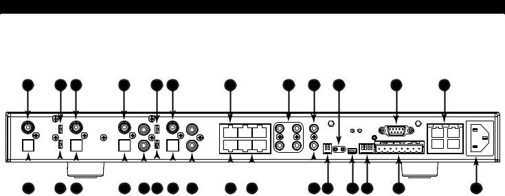
Rear Panel
The Rear Panel of the D5RH has connections for Power, Source Inputs, Zone Outputs, IR Outputs, Page/Doorbell Trigger Input, Auxiliary Power, USB and Expansion capabilities as well as
Digital/Analog Source Selection, Source Input Gain and Zone Pairing DIP Switches.
1 |
3 |
1 |
1 |
3 |
1 |
7 |
8 |
10 |
13 |
18 |
16 |
|
|
|
|
|
|
|
|
|
|
|
|
|
|
|
|
|
|
|
|
|
|
|
|
|
|
|
|
|
|
|
|
|
|
|
|
|
|
|
|
|
|
|
|
|
|
|
|
|
|
|
|
2 |
3 |
2 |
2 |
4 |
3 |
2 |
4 |
5 |
6 |
9 |
11 |
12 14 |
15 |
17 |
|||||||||||
|
|
|
|
|
|
|
|
|
|
|
|
|
Figure 1.2: D5RH Rear Panel |
|
|
|
|
||||||||
|
|
|
|
|
|
|
|
|
|
|
|
|
|
|
|
|
|
|
|
|
|
|
|
|
|
|
|
Connector |
|
|
|
|
|
|
|
|
|
|
|
Function |
|
|
|
|
|
|
|
||||
|
1 |
Digital Coaxial Audio Input |
|
|
|
Connect digital audio sources using Digital |
|
|
|||||||||||||||||
|
|
|
|
Coaxial cable |
|
|
|
|
|
||||||||||||||||
|
|
|
|
|
|
|
|
|
|
|
|
|
|
|
|
|
|
|
|
|
|
||||
|
2 |
Digital Optical Audio Input |
|
|
|
Connect digital audio sources using Digital |
|
|
|||||||||||||||||
|
|
|
|
Optical cable |
|
|
|
|
|
||||||||||||||||
|
|
|
|
|
|
|
|
|
|
|
|
|
|
|
|
|
|
|
|
|
|
||||
|
3 |
Coaxial/Optical/RCA Selection |
|
Select between Digital Coaxial, Digital Optical |
|
|
|||||||||||||||||||
|
Switch |
|
|
|
|
|
|
|
|
|
|
|
or RCA connection |
|
|
|
|
||||||||
|
|
|
|
|
|
|
|
|
|
|
|
|
|
|
|
|
|||||||||
|
4 |
Analog Audio Input |
|
|
|
|
|
|
|
Connect analog audio sources using RCA |
|
|
|||||||||||||
|
|
|
|
|
|
|
|
cables |
|
|
|
|
|
|
|
||||||||||
|
|
|
|
|
|
|
|
|
|
|
|
|
|
|
|
|
|
|
|
|
|
|
|
||
|
5 |
Expansion Port |
|
|
|
|
|
|
|
|
|
Control/Status Link to D5XH Digital Audio Hub |
|
|
|||||||||||
|
6 |
Source Loop Outputs |
|
|
|
|
|
Audio Links to D5XH |
|
|
|
|
|||||||||||||
|
7 |
D5-NET Port |
|
|
|
|
|
|
|
|
|
|
|
For future 2-way data sources & |
|
|
|||||||||
|
|
|
|
|
|
|
|
|
|
|
|
communication |
|
|
|
|
|
||||||||
|
|
|
|
|
|
|
|
|
|
|
|
|
|
|
|
|
|
|
|
|
|
||||
|
8 |
IR OUT Ports |
|
|
|
|
|
|
|
|
|
Source-specific IR ports to control audio |
|
|
|||||||||||
|
|
|
|
|
|
|
|
|
|
sources |
|
|
|
|
|
|
|
||||||||
|
|
|
|
|
|
|
|
|
|
|
|
|
|
|
|
|
|
|
|
|
|
|
|
||
|
9 |
ALL IR OUT Port |
|
|
|
|
|
|
|
|
|
Non-source-specific IR port |
|
|
|
||||||||||
|
10 |
Page/Doorbell Trigger Input |
|
Interface with Page/Doorbell system |
|
|
|||||||||||||||||||
|
11 |
Analog Source Input Gain |
|
|
|
Adjust Input GAIN from digital sources to avoid |
|
|
|||||||||||||||||
|
Switches |
|
|
|
|
|
|
|
|
|
|
|
distortion |
|
|
|
|
|
|
|
|||||
|
12 |
USB Port |
|
|
|
|
|
|
|
|
|
|
|
For firmware updates |
|
|
|
|
|||||||
|
13 |
Clip Indicators |
|
|
|
|
|
|
|
|
|
Displays clipping from sources |
|
|
|
||||||||||
|
14 |
Zone Pairing Switches |
|
|
|
|
|
Links multiple zones |
|
|
|
|
|||||||||||||
|
15 |
Auxiliary Power Output Port |
|
Provides additional power to D5KP Amplifier |
|
|
|||||||||||||||||||
|
|
Keypads |
|
|
|
|
|
|
|
||||||||||||||||
|
|
|
|
|
|
|
|
|
|
|
|
|
|
|
|
|
|
|
|
|
|
|
|
||
|
16 |
Zone Output Ports |
|
|
|
|
|
|
|
Connect |
to D5KP Amplifier Keypads located in |
|
|
||||||||||||
|
|
|
|
|
|
|
|
each zone |
|
|
|
|
|
||||||||||||
|
|
|
|
|
|
|
|
|
|
|
|
|
|
|
|
|
|
|
|
|
|
||||
|
17 |
AC Power Connector |
|
|
|
|
|
Plug into 110VAC wall outlet (Export 240VAC |
|
|
|||||||||||||||
|
|
|
|
|
|
models also available) |
|
|
|
||||||||||||||||
|
|
|
|
|
|
|
|
|
|
|
|
|
|
|
|
|
|
|
|
||||||
|
18 |
RS232 Port |
|
|
|
|
|
|
|
|
|
|
|
RS232 Communication Port. |
|
|
|
||||||||
|
|
|
|
|
|
|
|
|
|
|
|
|
|
|
Table 1.2: Rear Panel |
|
|
|
|
|
|||||
|
|
|
|
|
|
|
|
|
|
|
|
|
|
|
|
|
|
|
|
|
|
|
|
|
|
|
|
|
|
|
|
|
|
|
|
|
|
|
|
|
|
|
|
|
|
|
|
|
|
|
|
08905153B |
- 7 - |

2. System Design Overview/Applications
Planning
Before installing the D5RH, it is essential to have a detailed and accurate system design. The first step to a good design is to map the system. It is advisable to mark up a copy of the house floor plan with speaker, keypad and equipment locations, etc. Make sure that all locations are decided upon before pre-wiring so that all necessary wiring and installation hardware is in place.
It is essential that ALL system components are accounted for prior to the pre-wire stage. After establishing design goals, make a detailed list of all components. Include source equipment, keypad, expansion hubs, local source wall plates, IR emitters, etc.
Local Source
Speakers
D5KP
CAT-5
16/2 Speaker Wire
D5IP
Sources |
CAT-5 |
D5RH
Audio
Cables
CAT-5
D5XH
4X4 DDS EXPANSION HUB
Speakers
CAT-5
D5IP
CAT-5
16/2 Speaker Wire
D5KP
Audio
Cables
Local Source
Figure 2.1: System Wiring Overview
|
|
08905153B |
- 8 - |

Pre-Construction
In a pre-construction installation, walls and ceilings are open with no drywall installed. This is desirable and allows the installer greater access than in retro-fit applications. Before actually running any wire or cable, take the time to look around each room or area of the house and plan your wire paths for maximum efficiency. Look for routes through uncluttered parts of the stud wall or ceiling that allow you to group all low-voltage (video, speaker wires, CAT-5, telephone, etc.) wires wherever possible. It is a good practice to label both ends of all cables and to protect wires by tying a plastic bag over the ends.
Note: Do not run low-voltage wires closer than 12" from high-voltage wires. If necessary, cross lowvoltage wires at a 90º angle to prevent interference.
Retro-Fit Wiring/ Post Construction
Retro-fit installations are more difficult to complete than pre-construction because walls and ceilings are intact. Typically wires must be fished into position through walls, floors and ceilings. Holes must be cut; speakers mounted directly in the ceiling or walls with no rough-in brackets and keypads and local source wall plates must be mounted in existing drywall.
|
|
08905153B |
- 9 - |
Pre-Wiring
D5RH Digital Audio Distribution Hub to D5KP Amplifier Keypad
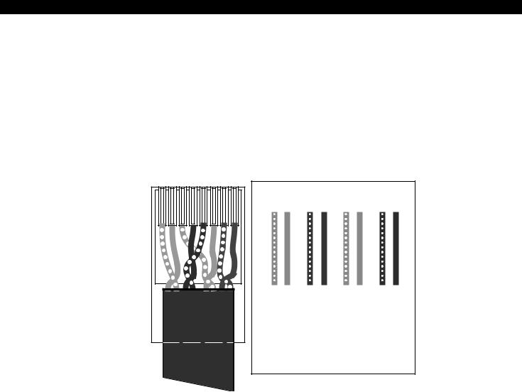
The D5RH and all associated components are wired using CAT-5 terminated to the T-568A Wiring Standard (Figure 2.2). When pre-wiring, run lengths of CAT-5 from the pre-determined equipment location (the “head-end”) to each Amplifier Keypad location. The CAT-5 routes all audio, power, IR and status information needed for full system operation.
Note: For maximum performance over long runs (more than 150 ft) run an additional 16AWG 2- conductor wire for external power.
1 2 3 4 5 6 7 8
Shown tab down
1 2 |
3 4 |
5 6 |
78 |
GREEN/WHITE |
GREEN |
ORANGE/WHITE |
BLUE |
BLUE/WHITE |
ORANGE |
BROWN/WHITE |
BROWN |
Figure 2.2: T-568A Wiring Standard
Amplifier Keypad to Speakers
Run 16AWG 2-conductor stranded copper speaker wire between Amplifier Keypad locations and speaker locations.
Local Sources to Amplifier Keypad
Local sources are only available within the area that they are installed. They will not be available to other areas of the house as they are not distributed by the D5RH. Run lengths of CAT-5 from any local (in-room) source to the Amplifier Keypad located in that area.
|
|
08905153B |
- 10 - |
 Loading...