


S105Q-3

DITCH BANK
ROTARY CUTTER
S105-3
S106-3
S105Q-3
S106Q-3
29977
(Rev. 1/23/2009)
TO THE DEALER:
®
Assembly and proper installation of this product is the responsibility of the Woods
and safety rules. Make sure all items on the Dealer’s Pre-Delivery and Delivery Check Lists in the Operator’s Manual
are completed before releasing equipment to the owner.
The dealer must complete the Product Registration online at the Woods Dealer Website or complete the mail-in
form included with the Operator’s Manual. If using the mail-in form, the dealer is to return the prepaid postage portion to
Woods, give one copy to the customer, and retain one copy. Failure to register the product does not diminish
customer’s warranty rights.
TO THE OWNER:
Read this manual before operating your Woods equipment. The information presented will prepare you to do a better and
safer job. Keep this manual handy for ready reference. Require all operators to read this manual carefully and become
acquainted with all adjustment and operating procedures before attempting to operate. Replacement manuals can be
obtained from your dealer. To locate your nearest dealer, check the Dealer Locator at www.WoodsEquipment.com, or in
the United States and Canada call 1-800-319-6637.
The equipment you have purchased has been carefully engineered and manufactured to provide dependable and
satisfactory use. Like all mechanical products, it will require cleaning and upkeep. Lubricate the unit as specified.
Observe all safety information in this manual and safety decals on the equipment.
For service, your authorized Woods dealer has trained mechanics, genuine Woods service parts, and the necessary
tools and equipment to handle all your needs.
Use only genuine Woods service parts. Substitute parts will void the warranty and may not meet standards required for
safe and satisfactory operation. Record the model number and serial number of your equipment in the spaces
provided:
dealer. Read manual instructions
Model: _______________________________ Date of Purchase: _____________________
Serial Number: (see Safety Decal section for location) ____________________________________
Provide this information to your dealer to obtain correct repair parts.
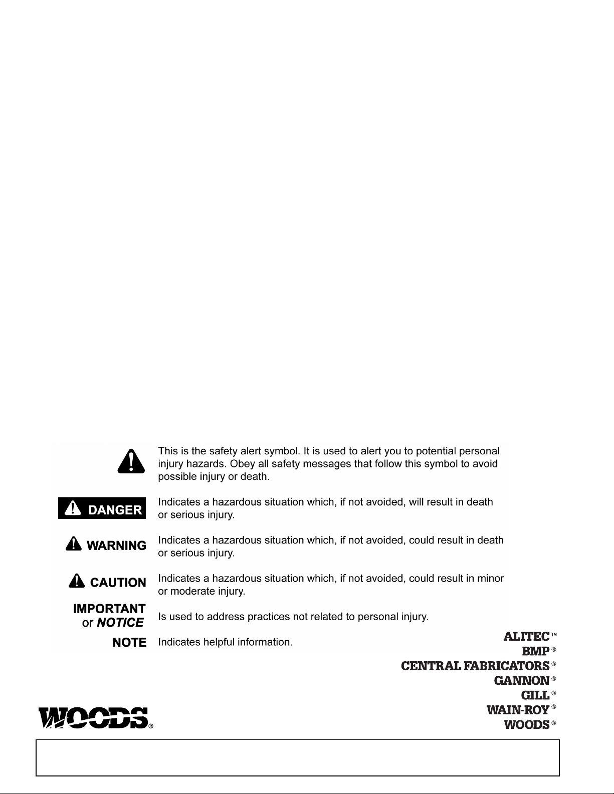
Throughout this manual, the term NOTICE is used to indicate that failure to observe can cause damage to equipment.
The terms CAUTION, WARNING, and DANGER are used in conjunction with the Safety-Alert Symbol (a triangle with
an exclamation mark) to indicate the degree of hazard for items of personal safety.
2 Introduction
Gen’l (Rev. 2/19/2008)

TABLE OF CONTENTS
INTRODUCTION . . . . . . . . . . . . . . . . . . . . . . . . . . . . . . . . . . . . . . . . . . . . . . 2
SPECIFICATIONS. . . . . . . . . . . . . . . . . . . . . . . . . . . . . . . . . . . . . . . . . . . . . 4
GENERAL INFORMATION . . . . . . . . . . . . . . . . . . . . . . . . . . . . . . . . . . . . . 4
SAFETY VIDEO ORDER FORM . . . . . . . . . . . . . . . . . . . . . . . . . . . . . . . . . . 5
SAFETY RULES . . . . . . . . . . . . . . . . . . . . . . . . . . . . . . . . . . . . . . . . . . . . . . 7
SAFETY DECALS . . . . . . . . . . . . . . . . . . . . . . . . . . . . . . . . . . . . . . . . . . . . 10
OPERATION . . . . . . . . . . . . . . . . . . . . . . . . . . . . . . . . . . . . . . . . . . . . . . . . 13
OWNER SERVICE . . . . . . . . . . . . . . . . . . . . . . . . . . . . . . . . . . . . . . . . . . . 17
TROUBLESHOOTING. . . . . . . . . . . . . . . . . . . . . . . . . . . . . . . . . . . . . . . . . 20
DEALER SERVICE . . . . . . . . . . . . . . . . . . . . . . . . . . . . . . . . . . . . . . . . . . . 21
DEALER CHECK LISTS . . . . . . . . . . . . . . . . . . . . . . . . . . . . . . . . . . . . . . . 28
ASSEMBLY . . . . . . . . . . . . . . . . . . . . . . . . . . . . . . . . . . . . . . . . . . . . . . . . . 29
PARTS INDEX. . . . . . . . . . . . . . . . . . . . . . . . . . . . . . . . . . . . . . . . . . . . . . . 35
BOLT TORQUE CHART . . . . . . . . . . . . . . . . . . . . . . . . . . . . . . . . . . . . . . . 54
BOLT SIZE CHART AND ABBREVIATIONS . . . . . . . . . . . . . . . . . . . . . . . 55
INDEX . . . . . . . . . . . . . . . . . . . . . . . . . . . . . . . . . . . . . . . . . . . . . . . . . . . . . 56
PRODUCT WARRANTY . . . . . . . . . . . . . . . . . . . . . . . . . . . . . . . . . . . . . . . 57
REPLACEMENT PARTS WARRANTY . . . . . . . . . . . . . . . . . . . BACK COVER
29977 (Rev. 1/23/2009)
Introduction 3

SPECIFICATIONS
WARNING
S105
Cutting Width 60" 60" 72" 72"
PTO Speed (rpm) 540 1000 540 1000
Blade Tip Speed (feet per minute) 11,451 14,137 10,178 12,566
Minimum Tractor Weight Recommended 4000 lbs 4000 lbs 5000 lbs 5000 lbs
Minimum Tractor HP Recommended 40 HP 40 HP 50 HP 50 HP
Minimum 3-Point Lift Capacity 2500 lbs 2500 lbs 3000 lbs 3000 lbs
Cutting Height (Depending on 3-point hitch height) . . . . . . . . . . . . . . . . . . . . . . . . . . . . . . . . . . . . . . 1-1/2" - 12"
3-Point Hitch (Category 1 pins are available) . . . . . . . . . . . . . . . . . . . . . . . . . . . . . . . . . . . . . . . . . . Category 2
Offset from Centerline Tractor PTO to Inside Edge of Cut (Approximate) . . . . . . . . . . . . . . . . . . . . . . . . . . . 63"
Transport Width from Centerline PTO to Right Side with Head Raised (Approximate) . . . . . . . . . . . . . . . . . 70"
S105Q S106 S106Q
GENERAL INFORMATION
Some illustrations in this manual show the cutter with safety shields removed to provide a better
view. The cutter should never be operated with any
safety shielding removed.
The purpose of this manual is to assist you in operating
and maintaining your cutter. Read it carefully. It furnishes information and instructions that will help you
achieve years of dependable performance. These
instructions have been compiled from extensive field
experience and engineering data. Some information
may be general in nature due to unknown and varying
operating conditions. However, through experience
and these instructions, you should be able to develop
procedures suitable to your particular situation.
The illustrations and data used in this manual were current at the time of printing, but due to possible inline
production changes, your machine may vary slightly in
detail. We reserve the right to redesign and change the
machines as may be necessary without notification.
Throughout this manual, references are made to right
and left directions. These are determined by standing
behind the equipment facing the direction of forward
travel. Blade rotation is clockwise as viewed from the
top of the cutter.
4 Introduction
29977 (Rev. 11/23/2009)

Free Mower Safety Video
Fill out and return the order form and we will send you a FREE VHS
or DVD video outlining
Industrial and Agricultural Mower Safety
Practices
. The 22 minute video, developed in cooperation with
AEM (Association of Equipment Manufacturers), reinforces the
proper procedures to follow while operating your mowing
equipment. The video does not replace the information contained in
the Operator’s Manual, so please review this manual thoroughly
before operating your new mowing equipment.
Safety Training
Does Make a Difference.
BE SAFE!
BE ALERT!
BE ALIVE!
BE TRAINED
Before Operating Mowers!
ASSOCIATION OF
EQUIPMENT
MANUFACTURERS
Safety Video Order Form
Safety Video Order Form (8/2/2005)
Safety 5

Also, available from the Association of Equipment Manufacturers:
A large variety of training materials (ideal for groups) are available for a nominal
charge from AEM. Following is a partial list:
● Training Package for Rotary Mowers/Cutters-English
Contains: DVD & VHS (English)
Guidebook for Rotary Mowers/Cutters (English)
AEM Industrial/Agricultural Mower Safety Manual (English)
AEM Agricultural Tractor Safety Manual (English)
● Training Package for Rotary Mowers/Cutters-English/Spanish
Contains: DVD & VHS (English/Spanish)
Guidebook for Rotary Mowers/Cutters (English/Spanish)
AEM Industrial/Agricultural Mower Safety Manual (English/Spanish)
AEM Agricultural Tractor Safety Manual (English/Spanish)
AEM training packages are available through:
AEM at:
or
Universal Lithographers, Inc.
Email: aem@ulilitho.com
800-369-2310 tel
866-541-1668 fax
www.aem.org
Free Mower/ Cutter Safety Video Order Form
3 (Select one)
VHS Format - VHS01052 Safety Video
Please send me
Name: ________________________________________ Phone: __________________
Address: _____________________________________
_____________________________________
_____________________________________
Mower/Cutter Model: ______________________ Serial #: ________________________
Send to: ATTENTION: DEALER SERVICES
WOODS EQUIPMENT COMPANY
PO BOX 1000
OREGON IL 61061-1000
DVD Format - DVD01052 Safety Video
6 Safety
Safety Video Order Form (Rev. 2/6/2006)

INSTALLATION
Safety is a primary concern in the design and
manufacture of our products. Unfortunately, our
efforts to provide safe equipment can be wiped
out by an operator’s single careless act.
In addition to the design and configuration of
equipment, hazard control and accident prevention are dependent upon the awareness, concern, judgement, and proper training of
personnel involved in the operation, transport,
maintenance, and storage of equipment.
It has been said, “The best safety device is an
informed, careful operator.” We ask you to be
that kind of operator.
SAFETY RULES
ATTENTION! BECOME ALERT! YOUR SAFETY IS INVOLVED!
Hydraulics must be connected as instructed in
this manual. Do not substitute parts, modify, or
connect in any other way.
TRAINING
Safety instructions are important! Read all
attachment and power unit manuals; follow all
safety rules and safety decal information. (Replacement manuals and safety decals are available from
your dealer. To locate your nearest dealer, check
the Dealer Locator at www.WoodsEquipment.com,
or in the United States and Canada call 1-800-319-
6637.) Failure to follow instructions or safety rules
can result in serious injury or death.
Never allow children or untrained persons to
operate equipment.
PREPARATION
Check that all hardware is properly installed.
Always tighten to torque chart specifications
unless instructed otherwise in this manual.
Air in hydraulic systems can cause erratic operation and allows loads or equipment components
to drop unexpectedly. When connecting equipment
or hoses or performing any hydraulic maintenance,
purge any air in hydraulic system by operating all
hydraulic functions several times. Do this before
putting into service or allowing anyone to
approach the equipment.
Make sure all hydraulic hoses, fittings, and
valves are in good condition and not leaking before
starting power unit or using equipment. Check and
route hoses carefully to prevent damage. Hoses
must not be twisted, bent sharply, kinked, frayed,
pinched, or come into contact with any moving
parts. Operate moveable components through full
operational range to check clearances. Replace
any damaged hoses immediately.
After connecting hoses, check that all control
lever positions function as instructed in the Operator's Manual. Do not put into service until control
lever and equipment movements are correct.
If you do not understand any part of this manual
and need assistance, see your dealer.
Know your controls and how to stop engine and
attachment quickly in an emergency.
Operators must be instructed in and be capable
of the safe operation of the equipment, its attachments, and all controls. Do not allow anyone to
operate this equipment without proper instructions.
Keep hands and body away from pressurized
lines. Use paper or cardboard, not hands or other
body parts to check for leaks. Wear safety goggles.
Hydraulic fluid under pressure can easily penetrate
skin and will cause serious injury or death.
Make sure that all operating and service personnel know that if hydraulic fluid penetrates skin, it
must be surgically removed as soon as possible by
a doctor familiar with this form of injury or gangrene, serious injury, or death will result. CONTACT A PHYSICIAN IMMEDIATELY IF FLUID
ENTERS SKIN OR EYES. DO NOT DELAY.
S/HS 105/106 Safety Rules (Rev. 7/7/2006)
Set tractor hydraulic relief valve at 2500 psi (170
bars) (17,000 kPa) to prevent injury and equipment
damage due to hydraulic system failure.
Your dealer can supply original equipment
hydraulic accessories and repair parts. Substitute
parts may not meet original equipment specifications and may be dangerous.
Always wear relatively tight and belted clothing
to avoid getting caught in moving parts. Wear
sturdy, rough-soled work shoes and protective
equipment for eyes, hair, hands, hearing, and head;
and respirator or filter mask where appropriate.
Make sure spring-activated locking pin or collar
slides freely and is seated firmly in tractor PTO
spline groove.
Make sure attachment is properly secured,
adjusted, and in good operating condition.
(Safety Rules continued on next page)
Safety 7

(Safety Rules continued from previous page)
SAFETY RULES
ATTENTION! BECOME ALERT! YOUR SAFETY IS INVOLVED!
Power unit must be equipped with ROPS or
ROPS cab and seat belt. Keep seat belt securely
fastened. Falling off power unit can result in death
from being run over or crushed. Keep foldable
ROPS system in “locked up” position at all times.
Remove accumulated debris from this equipment, power unit, and engine to avoid fire hazard.
Make sure all safety decals are installed.
Replace if damaged. (See Safety Decals section for
location.)
Make sure shields and guards are properly
installed and in good condition. Replace if damaged.
You must use a center frame counterweight box
filled with steel to a minimum 400 lbs.
Do not put this equipment into service unless all
side skids are properly installed and in good condition. Replace if damaged.
A minimum 20% of tractor and equipment
weight must be on the tractor front wheels when
attachments are in transport position. Without this
weight, tractor could tip over, causing personal
injury or death. The weight may be attained with a
loader, front wheel weights, ballast in tires or front
tractor weights. Weigh the tractor and equipment.
Do not estimate.
Inspect and clear area of stones, branches, or
other hard objects that might be thrown, causing
injury or damage.
Do not operate or transport equipment while
under the influence of alcohol or drugs.
Use additional caution and reduce speed when
under adverse surface conditions, turning, or on
inclines.
OPERATION
Do not allow bystanders in the area when operating, attaching, removing, assembling, or servicing equipment.
Never walk, stand, or place yourself or others
under a raised wing or in the path of a lowering
wing. Hydraulic system leak-down, hydraulic system failures, mechanical failures, or movement of
control levers can cause wings to drop unexpectedly and cause severe injury or death.
Full chain shielding must be installed when
operating in populated areas or other areas where
thrown objects could injure people or damage
property.
• If this machine is not equipped with full chain
shielding, operation must be stopped when anyone comes within 300 feet (92 m).
• This shielding is designed to reduce the risk
of thrown objects. The mower deck and protective devices cannot prevent all objects from
escaping the blade enclosure in every mowing
condition.
and escape, traveling as much as 300 feet (92 m).
Never direct discharge toward people, animals,
or property.
It is possible for objects to ricochet
TRANSPORTATION
Power unit must be equipped with ROPS or
ROPS cab and seat belt. Keep seat belt securely
fastened. Falling off power unit can result in death
from being run over or crushed. Keep foldable
ROPS system in “locked up” position at all times.
Before transporting, stop tractor PTO, raise cutter center section, then raise cutter head, and
install transport bar. A raised cutter head can fall
and crush. Keep away; never go underneath. Lower
cutter head after transport and for storage.
Always comply with all state and local lighting
and marking requirements.
Never allow riders on power unit or attachment.
Do not operate PTO during transport.
Do not operate or transport on steep slopes.
8 Safety
Do not operate or transport equipment while
under the influence of alcohol or drugs.
Operate only in daylight or good artificial light.
Keep hands, feet, hair, and clothing away from
equipment while engine is running. Stay clear of all
moving parts.
Never allow riders on power unit or attachment.
Power unit must be equipped with ROPS or
ROPS cab and seat belt. Keep seat belt securely
fastened. Falling off power unit can result in death
from being run over or crushed. Keep foldable
ROPS system in “locked up” position at all times.
Always sit in power unit seat when operating
controls or starting engine. Securely fasten seat
belt, place transmission in neutral, engage brake,
and ensure all other controls are disengaged
before starting power unit engine.
S/HS 105/106 Safety Rules (Rev. 7/7/2006)
(Rev. 1/23/2009)

Operate tractor PTO at 540 RPM (1000 RPM on Q
SAFETY RULES
ATTENTION! BECOME ALERT! YOUR SAFETY IS INVOLVED!
Series cutters). Do not exceed.
Raise or lower wings slowly to prevent personal
injury or damage to cutter.
Look down and to the rear and make sure area
is clear before operating in reverse.
Do not operate or transport on steep slopes.
Do not stop, start, or change directions sud-
denly on slopes.
Watch for hidden hazards on the terrain during
operation.
Stop power unit and equipment immediately
upon striking an obstruction. Turn off engine,
remove key, inspect, and repair any damage before
resuming operation.
ator's Manual instructions for working underneath
and blocking requirements or have work done by a
qualified dealer.
Make sure attachment is properly secured,
adjusted, and in good operating condition.
Keep all persons away from operator control
area while performing adjustments, service, or
maintenance.
Make certain all movement of equipment components has stopped before approaching for service.
Frequently check blades. They should be sharp,
free of nicks and cracks, and securely fastened.
Do not handle blades with bare hands. Careless
or improper handling may result in serious injury.
MAINTENANCE
Before dismounting power unit or performing
any service or maintenance, follow these steps:
disengage power to equipment, lower the 3-point
hitch and all raised components to the ground,
operate valve levers to release any hydraulic pressure, set parking brake, stop engine, remove key,
and unfasten seat belt.
Before performing any service or maintenance,
lower attachment to ground, turn off engine, set
parking brake, and remove key.
Do not modify or alter or permit anyone else to
modify or alter the equipment or any of its components in any way.
Your dealer can supply original equipment
hydraulic accessories and repair parts. Substitute
parts may not meet original equipment specifications and may be dangerous.
To prevent contamination, clean and then cover
hose ends, fittings, and hydraulic ports with tape.
Do not allow bystanders in the area when operating, attaching, removing, assembling, or servicing equipment.
Never go underneath equipment (lowered to the
ground or raised) unless it is properly blocked and
secured. Never place any part of the body underneath equipment or between moveable parts even
when the engine has been turned off. Hydraulic
system leak down, hydraulic system failures,
mechanical failures, or movement of control levers
can cause equipment to drop or rotate unexpectedly and cause severe injury or death. Follow Oper-
Your dealer can supply genuine replacement
blades. Substitute blades may not meet original
equipment specifications and may be dangerous.
Tighten all bolts, nuts, and screws to torque
chart specifications. Check that all cotter pins are
installed securely to ensure equipment is in a safe
condition before putting unit into service.
Make sure all safety decals are installed.
Replace if damaged. (See Safety Decals section for
location.)
Make sure shields and guards are properly
installed and in good condition. Replace if damaged.
Never perform service or maintenance with
engine running.
Do not disconnect hydraulic lines until machine
is securely blocked or placed in lowest position
and system pressure is released by operating
valve levers.
Service and maintenance work not covered in
OWNER SERVICE must be done by a qualified
dealership. Special skills, tools, and safety procedures may be required. Failure to follow these
instructions can result in serious injury or death.
STORAGE
Keep children and bystanders away from storage area.
Store on level, solid ground.
Block equipment securely for storage.
(Rev. 1/23/2009)
S/HS 105/106 Safety Rules (Rev. 7/7/2006)
Safety 9
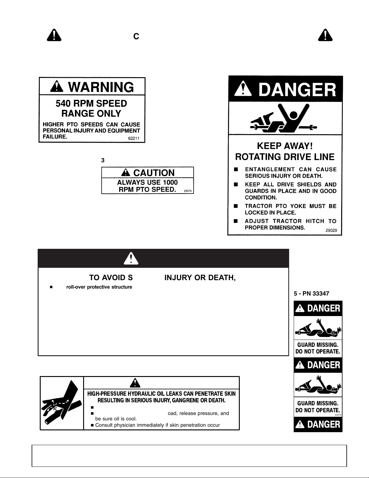
TO AVOID SERIOUS INJURY OR DEATH,
Read Operator’s Manual and follow all safety, operating, and service
instructions. (Contact dealer for manuals.)
Keep all guards and shields in place and in good condition.
Lower implement, shut off, and remove key before leaving or servicing.
Block up equipment and remove key before working underneath.
Never allow children or unqualified persons to operate.
Clear mowing area of all debris.
Be careful on uneven terrain. Reduce speed when turning.
32005-E
WARNING
1 - PN 32005
DANGER
ENTANGLEMENT WITH ROTATING DRIVE
PARTS OR FALLING OFF CAN CAUSE
INJURY OR DEATH.
KEEP ALL DRIVE SHIELDS AND GUARDS
IN PLACE AND IN GOOD CONDITION.
ALLOW NO RIDERS.
25023-H
KEEP AWAY!
2 - PN 25023
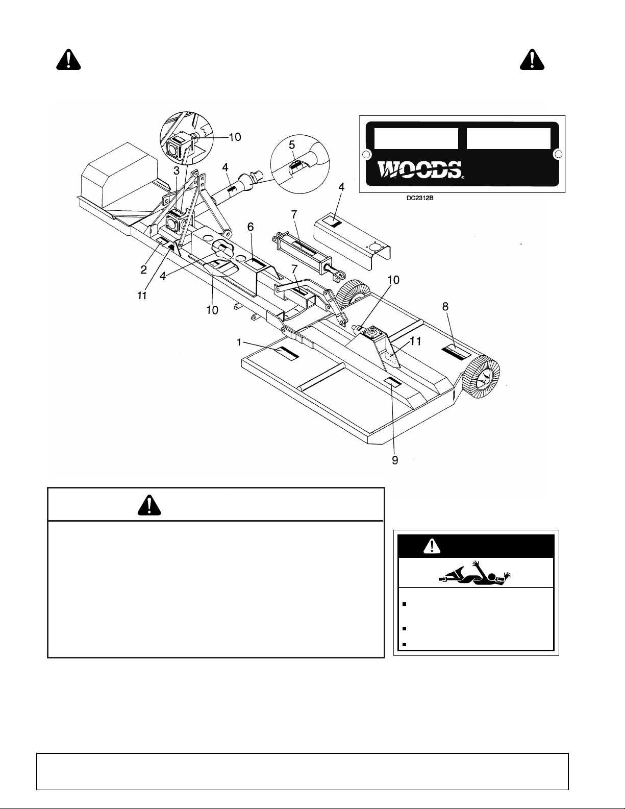
11 - SERIAL NUMBER PLATE
SAFETY & INSTRUCTIONAL DECALS
ATTENTION! BECOME ALERT! YOUR SAFETY IS INVOLVED!
Replace Immediately If Damaged!
MODEL NO. SER IAL NO.
Woods Equipment Company
Oregon, Illinois, U.S.A.
10 Safety
(Safety Decals continued on next page)
29977 (Rev. 1/20/2006)
GUARD MISSING.
DO NOT OPERATE.
DANGER
33347E
DANGER
DANGER
GUARD MISSING.
DO NOT OPERATE.
5 - PN 33347
,HTAEDROYRUJNISUOIRESDIOVAOT
HH erutcurtsevitcetorprevo-lloresU.tnempiuqesihthtiwstlebtaesdna
H .tespurotcartdiovaotthgiewdnaezistneici
ffusfosrotcartnoylnorewo
msihtesU
H .nrutrevodluocrotcartsa,edisllihnwodnorewomhtiwknabpeetsnoro
tcarteta
r
eporeveN
H edisrosni-evac,stuo-hsawdiovaotsknabpeetsgnolagniwomnehwnoitua
cemertxee
sU
.tnemknabmefforotc
artllupdluochcihwtfard
H rewomdnaerusolcneevitcetorprobacesU wolebsknabgniwomnehwgnidleihsniahc
.stcejbon
worhtmorfrotarepotcetorpotleveledarg
H
.t
ropsnartrofnia
hc
dnar
ab
pu
-kcolh
ctalsyaw
lA
H .noitisopdesiarnitinu
htiwdednettanurotcartevaelreveN
G-
72582
DANGER
6 - PN 28527
HIGH-PRESSURE HYDRAULIC OIL LEAKS CAN PENETRATE SKIN
RESULTING IN SERIOUS INJURY , GANGRENE OR DEATH.
n
Check for leaks with cardboard; never use hand.
n
Before loosening fittings: lower load, release pressure, and
be sure oil is cool.
n
Consult physician immediately if skin penetration occurs.
WARNING
19924-B
7 - PN 19924
3 - PN 62211
3 - PN 23376
-or-
4 - PN 29029
SAFETY & INSTRUCTIONAL DECALS
ATTENTION! BECOME ALERT! YOUR SAFETY IS INVOLVED!
Replace Immediately If Damaged!
(Safety Decals continued from previous page)
29977 (Rev. 1/20/2006)
Safety 11

SAFETY & INSTRUCTIONAL DECALS
BE CAREFUL!
Use a clean, damp cloth to clean safety decals.
Avoid spraying too close to decals when using a pressure
washer; high-pressure water can enter through very small
scratches or under edges of decals causing them to peel or
come off.
Replacement safety decals can be ordered free from your
Woods dealer. To locate your nearest dealer, check the Dealer
Locator at www.WoodsEquipment.com, or in the United States
and Canada call 1-800-319-6637.
8 - PN 32241
26483-H
9 - PN 26483
ATTENTION! BECOME ALERT! YOUR SAFETY IS INVOLVED!
Replace Immediately If Damaged!
12 Safety
29977 (Rev. 1/20/2006)
OPERATION
DANGER
WARNING
CAUTION
WARNING
DB2310
The operator is responsible for the safe operation of
the cutter. The operator must be properly trained.
Operators should be familiar with the cutter, the tractor,
and all safety practices before starting operation. Read
the safety rules and safety decals on page 7 through
page 12.
This machine is a heavy-duty cutter designed for ditchbank and side bank mowing. Five foot and six foot cutting heads are available in 540 rpm and 1000 rpm models.
The 1000 rpm unit is designated with the marking
“1000 rpm” on the front and rear center frame, and the
input gearbox has a “1000 rpm” tag attached to it.
Full chain shielding must be installed when
operating in populated areas or other areas where
thrown objects could injure people or damage
property.
• If this machine is not equipped with full chain
shielding, operation must be stopped when any-
one comes within 300 feet (92 m).
• This shielding is designed to reduce the risk
of thrown objects. The mower deck and protec-
tive devices cannot prevent all objects from
escaping the blade enclosure in every mowing
condition.
and escape, traveling as much as 300 feet (92 m).
It is possible for objects to ricochet
Operate tractor PTO at 540 RPM (1000 RPM on Q
Series cutters). Do not exceed.
GENERAL TRACTOR REQUIREMENTS
Mount on tractors of adequate size; 4000 lbs minimum
weight for S105, and 5000 lbs minimum weight for
S106. Tractors should have a minimum 3-point lift
capacity of 2500 lbs for the S105 and 3000 lbs for the
S106.
Stabilizer bars must be used on lower 3-point hitch
arms to minimize cutter side to side sway.
An adjustable, rigid top link must be used to achieve
the tilt adjustments.
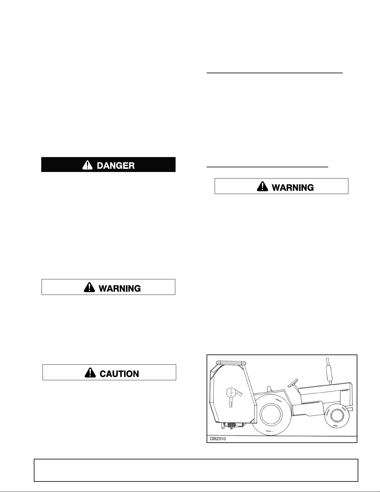
TRACTOR FRONT END STABILITY
A minimum 20% of tractor and equipment
weight must be on the tractor front wheels when
attachments are in transport position. Without this
weight, tractor could tip over, causing personal
injury or death. The weight may be attained with a
loader, front wheel weights, ballast in tires or front
tractor weights. Weigh the tractor and equipment.
Do not estimate.
You must use a center frame counterweight box
filled with steel to a minimum 400 lbs.
Never allow children or untrained persons to
operate equipment.
Keep bystanders away from equipment.
Never allow riders on power unit or attachment.
Keep all persons away from operator control
area while performing adjustments, service, or
maintenance.
Stop power unit and equipment immediately
upon striking an obstruction. Turn off engine,
remove key, inspect, and repair any damage before
resuming operation.
Always wear relatively tight and belted clothing
to avoid getting caught in moving parts. Wear
sturdy, rough-soled work shoes and protective
equipment for eyes, hair, hands, hearing, and head;
and respirator or filter mask where appropriate.
The use of 3-point mounted equipment can cause loss
of tractor front end stability.
If there is any question at all of the tractor stability or
the tractor rockshaft strength, use a counterweight of
approximately 400 lbs or more on left end of cutter center frame. The rockshaft is required to carry all torsion
load resulting from cutter head weight. Adding weight
to the left side of the cutter frame reduces the torsion
load.
Figure 1. Tractor Stability
29977 (Rev. 1/23/2009)
Operation 13

ATTACHING CUTTER TO TRACTOR
WARNING
WARNING
The cutter is shipped with Category 2 hitch pins.
Optional Category 1 pins may be substituted.
Attach check chain keyhole plates - one on each side
of tractor top link attaching lug.
Attach cutter center section to tractor 3-point hitch. Be
sure to use adjustable rigid top link. If tractor top link
pin is too short, use a 3/4 x 6" bolt.
PTO Drive Shaft
The standard drive shaft for this cutter is intended for
use with tractors having from 15" - 24" between the end
of PTO shaft and hitch pin holes of lower 3-point lift
arms when they are horizontal.
When PTO/hitch pin distance is less than 15", slip
tubes of PTO shaft can bottom out when operating over
uneven terrain.
When PTO/hitch pin distance is longer than 24", there
may not be sufficient engagement when operating over
uneven terrain. Longer drive halves are available (refer
to parts list on page 40).
Make sure spring-activated locking pin or collar
slides freely and is seated firmly in tractor PTO
spline groove.
CUTTING HEIGHT &
ATTITUDE ADJUSTMENT
Place tractor and cutter on a level area. Lower cutting
head (parallel to ground but suspended in air). Adjust
tractor 3-point lower arms to position cutter center section level from side to side and level with the cutting
head. On some tractors, the left lift arm can telescope
up or be locked down. When using this cutter, it must
be locked down.
With center section height adjusted, adjust tractor top
link to position front of cutter head approximately 1/2"
to 1" lower than the rear for normal cutting.
Gauge wheels may be adjusted to four different settings. Set the inside and outside wheels in the same
hole at the desired cutting height.
Check chains are optional but are recommended.
Adjust check chains to carry the cutter level and at
desired height when 3-point lift is released and allowed
to return to its lowest position.
SIDE SKID ADJUSTMENT
Side skids are designed to carry cutter head over
uneven ground and minimize scalping. With the cutting
height set and cutter level, set outer skid 1/2" above
ground level and inner skid 1" above ground.
Do not operate cutter with skids in constant contact
with the ground.
OPTIONAL TAILWHEEL ADJUSTMENT
The tailwheel is optional and is designed to be used on
the center section. The tailwheel will share the torsional
loads when mowing steep ditch banks. Set the tailwheel to ride on the ground after all other adjustments
are made.
PRE-OPERATION CHECK LIST
Owner’s Responsibility
___ Check to ensure blades are sharp, secure, and
cutting edges are positioned in the direction of
crossbar rotation.
___ Check to be sure each gearbox is half full of 90W
gear lube and has vent plug installed.
___ Check to ensure PTO shaft and cutter head uni-
versal joints and all other lubrication points are
properly serviced.
___ Check to ensure all safety shielding is properly
installed and in good condition.
___ Check to ensure PTO shielding rotates freely.
___ Clear mowing area of debris that could be picked
up and thrown by cutter.
___ Check cutting height and cutter attitude.
___ Place tractor PTO and transmission in neutral
before attempting to start engine.
___ Review and follow all safety practices presented
on page 7 through page 12.
NOTICE
■ Make sure all hydraulic connections are tight
and all hydraulic lines and hoses are in good condition before engaging tractor PTO.
Keep hands and body away from pressurized
lines. Use paper or cardboard, not hands or other
body parts to check for leaks. Wear safety goggles.
Hydraulic fluid under pressure can easily penetrate
skin and will cause serious injury or death.
Make sure that all operating and service personnel know that if hydraulic fluid penetrates skin, it
must be surgically removed as soon as possible by
a doctor familiar with this form of injury or gangrene, serious injury, or death will result. CONTACT A PHYSICIAN IMMEDIATELY IF FLUID
ENTERS SKIN OR EYES. DO NOT DELAY.
14 Operation
29977 (Rev. 1/23/2009)

Do not disconnect hydraulic lines until machine
WARNING
WARNING
CAUTION
DANGER
WARNING
is securely blocked or placed in lowest position
and system pressure is released by operating
valve levers.
GENERAL MOWING
Look down and to the rear and make sure area
is clear before operating in reverse.
This cutter may be used for mowing in either forward or
reverse. Reverse mowing will enable you to cut close
to obstructions. When mowing in both directions, cutter
should be level front to rear.
Blade Selection
Always use the tractor hydraulic system with built-in
float when available. On tractors with closed-center
systems that do not have float, you may lock the control in the down mode. This will allow the head to float.
Do not lock the control in the down mode on tractors
with open-center systems. Refer to the tractor owner's
manual or contact your dealer if you have questions as
to the type of hydraulic system used on your tractor.
Operate the open-center system that does not have a
float with the control in the neutral position. This will
allow cutter head to float up when encountering an
obstruction.
For tractors without hydraulic controls, an auxiliary control valve may be used. It has three positions: pull out
to raise, push in to slightly lower, and push all the way
in and snap into detent to allow cutter head to float.
Tractor and Cutter Operation
Your dealer can supply genuine replacement
blades. Substitute blades may not meet original
equipment specifications and may be dangerous.
General purpose suction blades are recommended for
normal mowing. Flat blades are recommended for
brush mowing and in sandy areas where abrasive
action could cause excessive blade wear. Final blade
selection must be left to your judgement, depending on
the job to be accomplished and the desired results.
Cutter Head Hydraulic Lift
The cutter head is raised with a 3-1/2" single-acting
hydraulic cylinder. The cylinder, which lifts only, may be
controlled by either tractor hydraulic controls or an
optional auxiliary hydraulic valve. The head is lowered
by gravity.
There is an orifice restrictor in the hydraulic line to control the fall.
NOTICE
■ Always raise center section before raising or
lowering cutter head. This will provide clearance
for the inside gauge wheel. Failure to raise center
section will result in rolling tire off of rim.
■ Never install a double-acting cylinder as dam-
age to the cutter will occur.
When mowing, set hydraulic valve in the float position.
This will allow cutter to follow the ground contour.
Full chain shielding must be installed when
operating in populated areas or other areas where
thrown objects could injure people or damage
property.
• If this machine is not equipped with full chain
shielding, operation must be stopped when anyone comes within 300 feet (92 m).
• This shielding is designed to reduce the risk
of thrown objects. The mower deck and protective devices cannot prevent all objects from
escaping the blade enclosure in every mowing
condition.
and escape, traveling as much as 300 feet (92 m).
Keep bystanders away from equipment.
Never allow riders on power unit or attachment.
This cutter is operated with tractor controls. Engage the
PTO control at idle rpm to prevent undue stress on
tractor, cutter drivelines and gearboxes. Set tractor
PTO speed and tractor throttle to operate at either 540
rpm or 1000 rpm, depending on which model cutter you
have. Change ground travel by using higher or lower
gears. Be sure operator is familiar with all tractor controls and can stop it and the cutter in an emergency.
The operator should give complete, undivided attention
to operating the tractor and cutter when mowing.
It is possible for objects to ricochet
29977 (Rev. 1/23/2009)
Operation 15
Brush and Ditch Bank Mowing
WARNING
WARNING
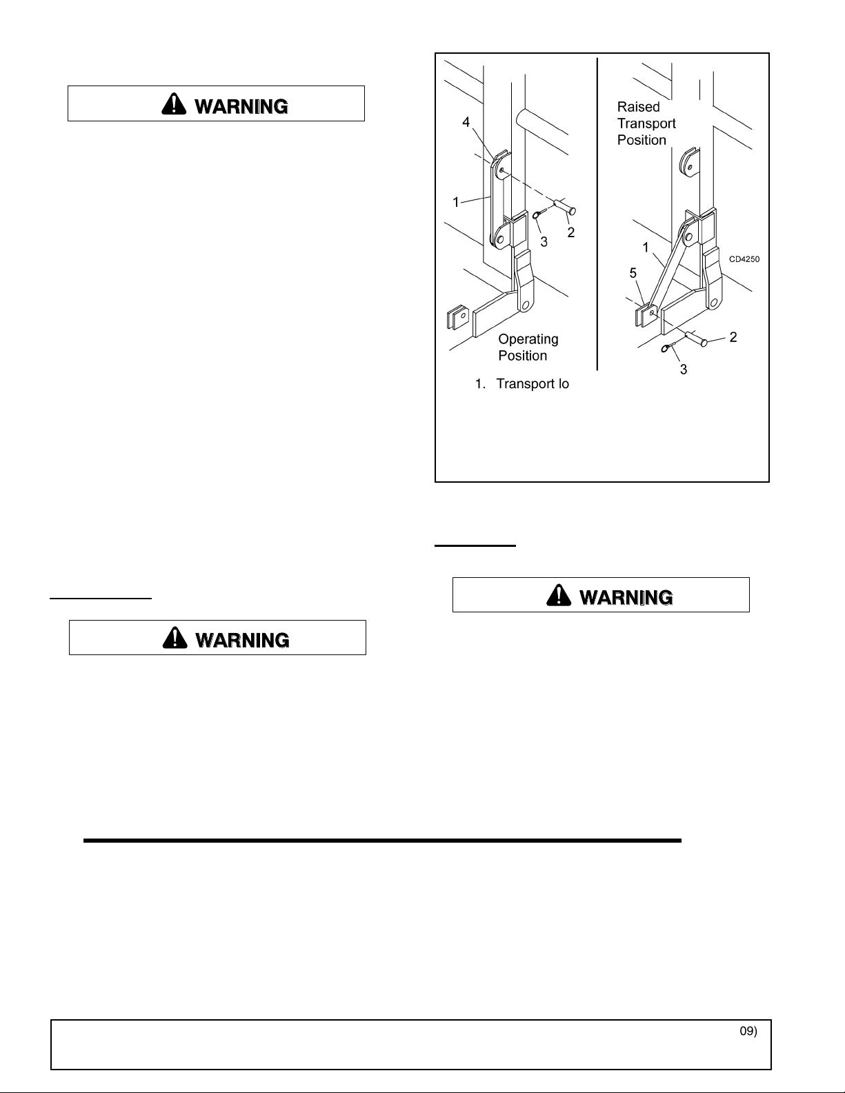
1. Transport lock-up bar
2. Clevis pin
3. Klik pin
4. Cutter storage lug
5. Center frame transport lug
WARNING
Never direct discharge toward people, animals,
or property.
■ Do not raise cutter head with PTO engaged. A
raised cutter head exposes blades and increases
thrown object hazards. Always operate with cutter
head close to surface being cut.
When operating this cutter on ditch banks and cutting
brush, the operator must be alert. Should the cutter hit
an obstruction, the front of the tractor will usually slide
toward the ditch (to the right). It would be possible to
run the tractor and cutter into the ditch if mowing speed
is too high or operator is not alert. On steep banks, it
may be necessary to use the left turning brake to counteract the load occurring when cutter is hitting brush.
This cutter can handle brush up to 3" without serious
damage if reasonable judgement is used. Sometimes,
in ditches, it is well to raise the center section and cutter head as high as needed and then lower it gradually
onto top of brush. This will produce a good shredding
job and usually is the best method for heavy brush.
When mowing steep banks with cutter on the uphill
side, it is possible to raise cutter head high enough to
over-center and make it difficult to lower. When this
occurs, it will be necessary to maneuver tractor to
cause lowering to take place.
TRANSPORT
■ Before transporting, stop tractor PTO, raise
cutter center section, then raise cutter head and
install transport bar. A raised cutter head can fall
and crush. Keep away; never go underneath. Lower
cutter head after transport and for storage.
When transporting the machine or working on the
underside, attach lock-up bar (1) to center frame (5),
using clevis pin (2), and secure with klik pin (3).
Figure 2. Lock-Up Bar
STORAGE
Do not disconnect hydraulic lines until machine
is securely blocked or placed in lowest position
and system pressure is released by operating
valve levers.
When unhooking and parking the cutter, lower cutter
head to ground. Place 12" blocks under both ends of
the center frame. Lower center frame until 3-point arms
are released and then disconnect. Be sure to disconnect PTO and hydraulic lines before moving tractor
away.
16 Operation
(Rev. 1/23/2009)
29977 (Rev. 1/23/2009)
OWNER SERVICE
WARNING
CAUTION
WARNING
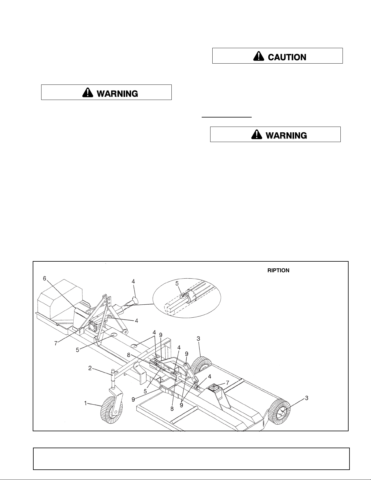
REF DESCRIPTION FREQUENCY
1 Tailwheel Daily
2 Tailwheel Pivot Daily
3 Gauge Wheels Daily
4 U-Joint 10 Hours
5 PTO Shaft (Lube all 4
sides)
10 Hours
6 PTO Cross Shaft 10 Hours
7 Gearbox (1/2 full of 90W
gear lube)
10 Hours
8 Bearing Blocks (one pump
w/grease gun)
24 Hours
9 Lift Pivot Bushing (oil) Daily
The information in this section is written for operators
who possess basic mechanical skills. If you need help,
your dealer has trained service technicians available.
For your protection, read and follow the safety information in this manual.
■ For service and adjustments, lower center
frame and cutter head to ground and disconnect
cutter driveline from tractor PTO. Raise as needed
for working room and securely block all sections of
this equipment before working underneath. Blocking up prevents cutter dropping from hydraulic
leak down, hydraulic system failures, or mechanical component failures.
■ When transporting the machine or working on
the underside, attach lock-up bar as shown on
page 16.
Make sure shields and guards are properly
installed and in good condition. Replace if damaged.
Do not disconnect hydraulic lines until machine
is securely blocked or placed in lowest position
and system pressure is released by operating
valve levers.
Operate tractor PTO at 540 RPM (1000 RPM on Q
Series cutters). Do not exceed.
Always wear relatively tight and belted clothing
to avoid getting caught in moving parts. Wear
sturdy, rough-soled work shoes and protective
equipment for eyes, hair, hands, hearing, and head;
and respirator or filter mask where appropriate.
LUBRICATION
■ Lower cutter head to ground, shut off tractor
engine and remove key before servicing.
Do not let excess grease collect on or around parts,
particularly when operating in sandy areas.
Figure 3 shows the lubrication points. The chart gives
the frequency in operating hours based on normal
operating conditions. Severe or unusual conditions
may require more frequent lubrication. Some reference
numbers have more than one location; be sure to
check number of points.
Use an SAE multi-purpose type grease. Be sure to
clean fitting thoroughly before using grease gun.
Use a good quality 90W gear lube in gearboxes.
29977 (Rev. 1/23/2009)
Figure 3. Lubrication Points
Owner Service 17
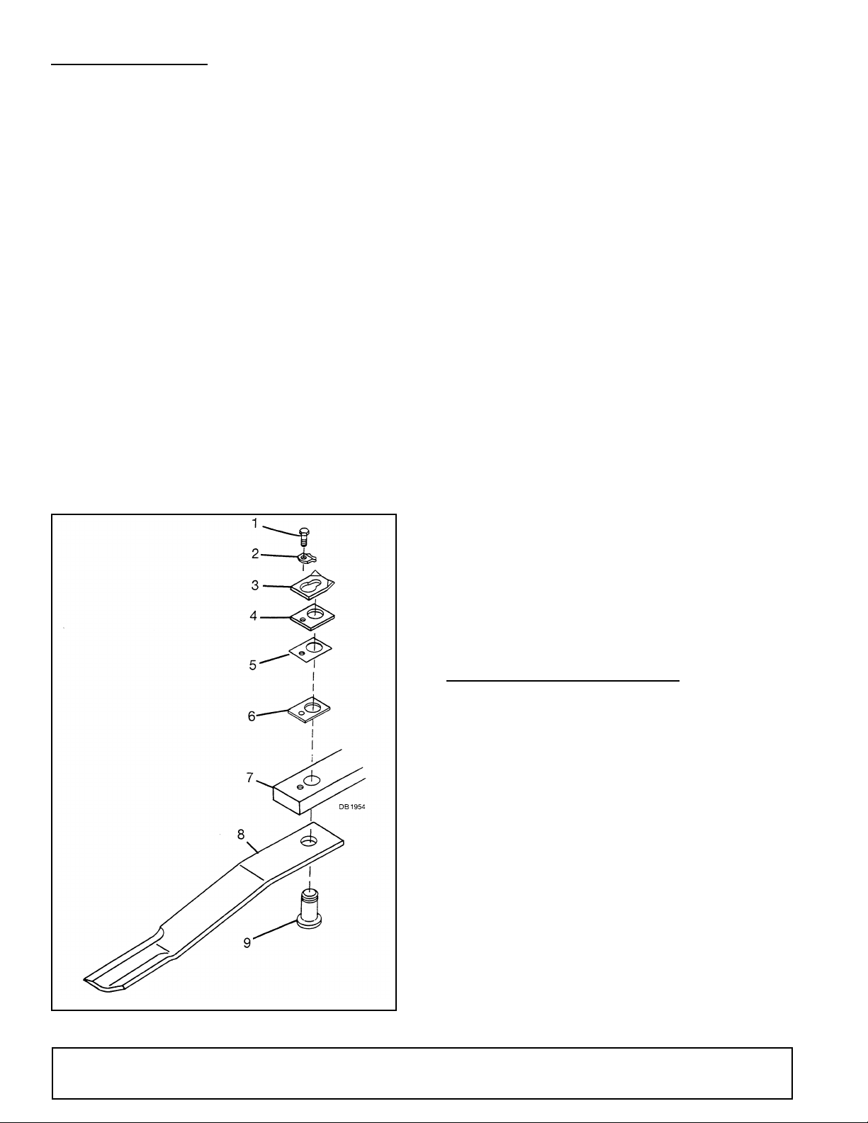
BLADE SERVICING
1. 1/2 NC x 1-1/4 HHCS GR5
2. Blade lock clip
3. Keyhole plate
4. 3/16” Spacer
5. Shim, 20 ga
6. Shim, 18 ga
7. Crossbar assembly
8. Blade
9. Blade pin
Blade Installation
NOTICE
■ Do not handle blades with bare hands. Care-
less or improper handling may result in serious
injury.
Raise wings and lock in up position. Inspect blades
before each use to determine that they are properly
installed and in good condition. Check to be sure
blades are snug but still swivel on blade pin (see Blade
Installation). Replace any blade that is bent, excessively nicked, worn or has any other damage. Small
nicks can be ground out when sharpening.
Blade Removal
Align crossbar and blade pin assembly with blade
access hole in cutter frame. Remove bolt (1) and blade
pin lock clip (2). Slide keyhole plate (3) out of blade pin
groove and remove. Remove spacers and drive pin out
of crossbar.
NOTICE
■ If blade is seized in crossbar and extreme force
will be required to remove it, support crossbar
from below to prevent gearbox damage.
Apply liberal coating of Never Seez® or equivalent to
blade pin and crossbar hole. Make sure blade is offset
away from deck with cutting edge toward direction of
rotation. Install pin (9) through blade (8) and push up
tightly against crossbar (7). Install as many spacers as
possible, allowing enough space for keyhole plate (3)
to slide into groove of blade pin. Keyhole plate (3) must
be installed with formed ears up as shown. Insert lock
clip (2) over keyhole plate and into blade pin groove
and secure with bolt (1). When installation is complete,
blade should be snug, but still swivel on pin without
excessive force. Retain any spacers not used in shimming blade to be used when either installing new blade
or when blade wear occurs.
NOTICE
■ Crossbar rotation is counter-clockwise when
looking down on the cutter.
■ When sharpening blades grind each blade the
same amount to maintain balance. When replacing
blades, replace in pairs. Unbalanced blades will
cause excessive vibration which can damage gearbox bearings. Vibration may also cause structural
cracks in cutter housing.
Blade Sharpening
Always sharpen all blades at the same time to maintain
balance. Follow original sharpening pattern. Do not
sharpen blade to a razor edge, but leave at least a
1-1/16" blunt edge. Do not sharpen back side of blade.
SLIP CLUTCH ADJUSTMENT
A slip clutch is designed to slip, protecting the gearbox
and driveline, should the cutter strike an obstruction.
When a unit sets for a long period of time, such as winter storage, the clutch can rust and seize. When this
occurs, loosen the spring tension and pry clutch plates
apart. Engage PTO and slip clutch. Adjust clutch as
specified.
The maximum the springs should be compressed on a
standard clutch is 1-3/4" at dimension “A”.
For a heavy-duty clutch and wing drive clutches, compress springs a minimum of 1-25/32" and a maximum
of 1-13/16" at dimension “A”.
Figure 4. Blade Removal
18 Owner Service
If a clutch continues to slip with springs compressed to
the maximum settings, check friction discs for excessive wear. Discs are 1/8" thick when new. Replace after
1/32" wear. (Minimum disc thickness is 3/32".)
29977 (Rev. 1/23/2009)
 Loading...