


Rev. 1/12/2007
MAN0260
HERITAGE REAR DISCHARGE MOWER
RDC54
RD60
RD72
Tested. Proven. Unbeatable.

 OPERATOR'S MANUAL

TO THE DEALER:
Assembly and proper installation of this product is the responsibility of the Woods® dealer. Read manual instructions and safety rules. Make sure all items on the Dealer’s Pre-Delivery and Delivery Check Lists in the Operator’s Manual are completed before releasing equipment to the owner.
The dealer must complete the Product Registration included with the Operator’s Manual. The customer must sign the registration which certifies that all Dealer Check List items have been completed. The dealer is to return the prepaid postage portion to Woods, give one copy to the customer, and retain one copy. Failure to complete and return this card does not diminish customer’s warranty rights.
TO THE OWNER:
Read this manual before operating your Woods equipment. The information presented will prepare you to do a better and safer job. Keep this manual handy for ready reference. Require all operators to read this manual carefully and become acquainted with all adjustment and operating procedures before attempting to operate. Replacement manuals can be obtained from your dealer. To locate your nearest dealer, check the Dealer Locator at www.WoodsEquipment.com, or in the United States and Canada call 1-800-319-6637.
The equipment you have purchased has been carefully engineered and manufactured to provide dependable and satisfactory use. Like all mechanical products, it will require cleaning and upkeep. Lubricate the unit as specified. Observe all safety information in this manual and safety decals on the equipment.
For service, your authorized Woods dealer has trained mechanics, genuine Woods service parts, and the necessary tools and equipment to handle all your needs.
Use only genuine Woods service parts. Substitute parts will void the warranty and may not meet standards required for safe and satisfactory operation. Record the model number and serial number of your equipment in the spaces provided:
Model: _______________________________ |
Date of Purchase: _____________________ |
Serial Number: (see Safety Decal section for location) ____________________________________
Provide this information to your dealer to obtain correct repair parts.
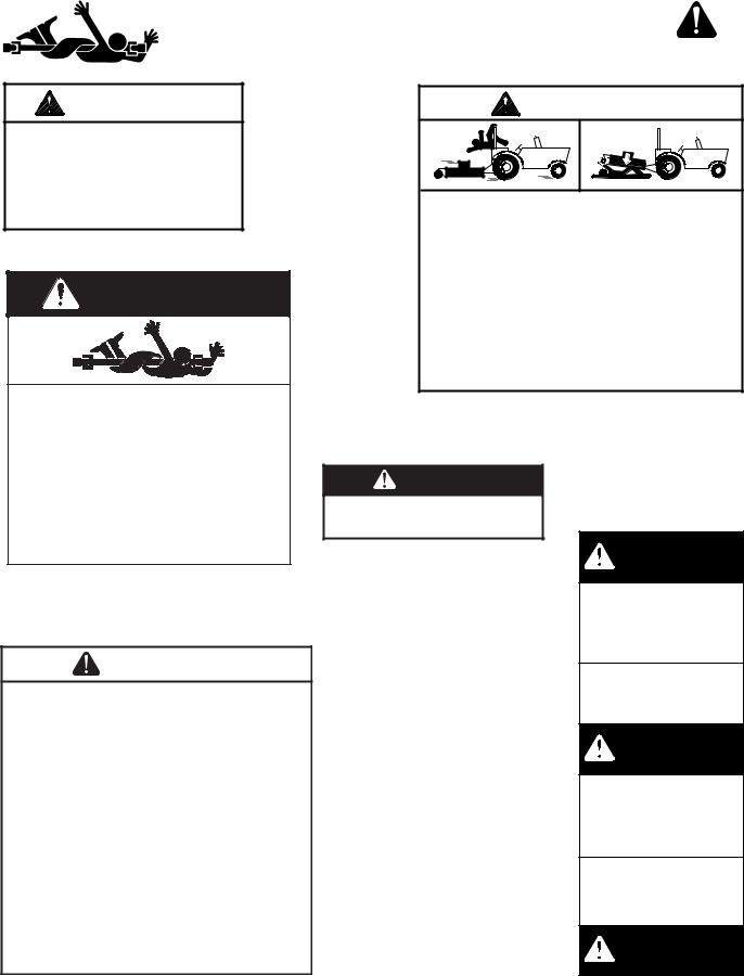
Throughout this manual, the term IMPORTANT is used to indicate that failure to observe can cause damage to equipment. The terms CAUTION, WARNING, and DANGER are used in conjunction with the Safety-Alert Symbol (a triangle with an exclamation mark) to indicate the degree of hazard for items of personal safety.

 DANGER
 WARNING
 CAUTION
IMPORTANT NOTE
This Safety-Alert Symbol indicates a hazard and means ATTENTION! BECOME ALERT! YOUR SAFETY IS INVOLVED!
Indicates an imminently hazardous situation that, if not avoided, will result in death or serious injury.
Indicates a potentially hazardous situation that, if not avoided, could result in death or serious injury, and includes hazards that are exposed when guards are removed.
Indicates a potentially hazardous situation that, if not avoided, may result in minor or moderate injury.
Indicates that failure to observe can cause damage to equipment.
Indicates helpful information.
|
|
|
|
2 Introduction |
Gen’l (Rev. 6/6/2005) |
||
|
|
|
|
TABLE OF CONTENTS
INTRODUCTION . . . . . . . . . . . . . . . . . . . . . . . . . . . . . . . . . . . . . . . . . . . . . . 2 SPECIFICATIONS. . . . . . . . . . . . . . . . . . . . . . . . . . . . . . . . . . . . . . . . . . . . . 4 GENERAL INFORMATION . . . . . . . . . . . . . . . . . . . . . . . . . . . . . . . . . . . . . . 4 SAFETY RULES . . . . . . . . . . . . . . . . . . . . . . . . . . . . . . . . . . . . . . . . . . . . . . 5 SAFETY DECALS . . . . . . . . . . . . . . . . . . . . . . . . . . . . . . . . . . . . . . . . . . . . . 8 OPERATION . . . . . . . . . . . . . . . . . . . . . . . . . . . . . . . . . . . . . . . . . . . . . . . . 10 OWNER SERVICE . . . . . . . . . . . . . . . . . . . . . . . . . . . . . . . . . . . . . . . . . . . 14 TROUBLESHOOTING . . . . . . . . . . . . . . . . . . . . . . . . . . . . . . . . . . . . . . . . 18 DEALER SERVICE . . . . . . . . . . . . . . . . . . . . . . . . . . . . . . . . . . . . . . . . . . . 20 ASSEMBLY . . . . . . . . . . . . . . . . . . . . . . . . . . . . . . . . . . . . . . . . . . . . . . . . . 27 DEALER CHECK LISTS . . . . . . . . . . . . . . . . . . . . . . . . . . . . . . . . . . . . . . . 31 PARTS LISTS . . . . . . . . . . . . . . . . . . . . . . . . . . . . . . . . . . . . . . . . . . . . . . . 33 BOLT TORQUE CHART . . . . . . . . . . . . . . . . . . . . . . . . . . . . . . . . . . . . . . . 43 BOLT SIZE CHART & ABBREVIATIONS . . . . . . . . . . . . . . . . . . . . . . . . . . 44 INDEX . . . . . . . . . . . . . . . . . . . . . . . . . . . . . . . . . . . . . . . . . . . . . . . . . . . . . 45 REPLACEMENT PARTS WARRANTY . . . . . . . . . . . . . . . . . . . . . . . . . . . . 48 PRODUCT WARRANTY . . . . . . . . . . . . . . . . . . . . . . . INSIDE BACK COVER
!LEA EL INSTRUCTIVO!
Si no lee Ingles, pida ayuda a alguien que si lo lea para que le traduzca las medidas de seguridad.
MAN0260 (Rev. 1/12/2007) |
Introduction 3 |
|
|

SPECIFICATIONS
MODEL |
RDC54 |
RD60 |
RD72 |
3-Point Hitch |
Limited Cat. 1 |
Cat. 1 |
Cat. 1 |
Cutting Width |
54" |
60" |
72" |
Cutting Height Range |
1" - 4-1/2" |
1" - 4-1/2" |
1" - 4-1/2" |
Operating Weight with |
|
|
|
Chain Shielding |
417 lbs. |
521 lbs. |
624 lbs. |
Blade Speed (feet per minute) |
16,200 |
18,000 |
18,100 |
Blade Spindles |
3 |
3 |
3 |
Number of Blades |
3 |
3 |
3 |
Universal Drive Series |
ASAE Cat. 3 |
ASAE Cat. 3 |
ASAE Cat. 3 |
Caster Wheels |
3.5 x 4 x 10 |
3.5 x 4 x 10 |
3.5 x 4 x 10 |
Tractor PTO Speed RPM |
540 |
540 |
540 |
Recommended Maximum |
|
|
|
Tractor Horsepower |
15-25 |
25-35 |
25-35 |
Mower Frame Thickness |
10 GA |
8 GA |
8 GA |
GENERAL INFORMATION
The purpose of this manual is to assist you in operating and maintaining your mower. Read it carefully. It furnishes information and instructions that will help you achieve years of dependable performance. These instructions have been compiled from extensive field experience and engineering data. Some information may be general in nature, due to unknown and varying operating conditions. However, through experience and these instructions, you should be able to develop procedures suitable to your particular situation.

The illustrations and data used in this manual were current at the time of printing. However, due to possible inline production changes, your machine may vary slightly in detail. We reserve the right to redesign and change the machines as may be necessary without notification.
Throughout this manual, references are made to right and left directions. These are determined by standing behind the tractor facing the direction of forward travel.
■ Some illustrations in this manual show the mower with safety shields removed to provide a better view. The mower should never be operated with any safety shielding removed.
4 Introduction |
MAN0260 (Rev. 1/12/2007) |
|
|

SAFETY RULES
ATTENTION! BECOME ALERT! YOUR SAFETY IS INVOLVED!
Safety is a primary concern in the design and manufacture of our products. Unfortunately, our efforts to provide safe equipment can be wiped out by an operator’s single careless act.
In addition to the design and configuration of equipment, hazard control and accident prevention are dependent upon the awareness, concern, judgement, and proper training of personnel involved in the operation, transport, maintenance and storage of equipment.
It has been said “The best safety device is an informed, careful operator.” We ask you to be that kind of operator.
TRAINING
Safety instructions are important! Read all attachment and power unit manuals; follow all safety rules and safety decal information. (Replacement manuals and safety decals are available from your dealer. To locate your nearest dealer, check the Dealer Locator at www.WoodsEquipment.com, or in the United States and Canada call 1-800-319- 6637.) Failure to follow instructions or safety rules can result in serious injury or death.
Know your controls and how to stop engine and attachment quickly in an emergency.
If you do not understand any part of this manual and need assistance, see your dealer.
Operators must be instructed in and be capable of the safe operation of the equipment, its attachments, and all controls. Do not allow anyone to operate this equipment without proper instructions.
Never allow children or untrained persons to operate equipment.
PREPARATION
Check that all hardware is properly installed. Always tighten to torque chart specifications unless instructed otherwise in this manual.
Always wear relatively tight and belted clothing to avoid entanglement in moving parts. Wear sturdy, rough-soled work shoes and protective equipment for eyes, hair, hands, hearing, and head; and respirator or filter mask where appropriate.
Make sure attachment is properly secured, adjusted, and in good operating condition.
Make sure spring-activated locking pin or collar slides freely and is seated firmly in tractor PTO spline groove.
Make sure driveline shield tether chains are attached to the tractor and equipment as shown in this manual. Replace if damaged or broken. Check that driveline guards rotate freely on driveline before putting equipment into service.
Before starting power unit, check all equipment driveline guards for damage. Replace any damaged guards. Make sure all guards rotate freely on all drivelines. If guards do not rotate freely on drivelines, repair and replace bearings before putting equipment into service.
Power unit must be equipped with ROPS or ROPS cab and seat belt. Keep seat belt securely fastened. Falling off power unit can result in death from being run over or crushed. Keep foldable ROPS systems in “locked up” position at all times.
Power unit must be equipped with ROPS or ROPS cab and seat belt. Keep seat belt securely fastened. Falling off power unit can result in death from being run over or crushed. Keep foldable ROPS systems in “locked up” position at all times.
Remove accumulated debris from this equipment, power unit, and engine to avoid fire hazard.
Make sure all safety decals are installed. Replace if damaged. (See Safety Decals section for location.)
Make sure shields and guards are properly installed and in good condition. Replace if damaged.
A minimum 25% of tractor and equipment weight must be on the tractor front wheels when attachments are in transport position. Without this weight, tractor could tip over, causing personal injury or death. The weight may be attained with a loader. Weigh the tractor and equipment. Do not estimate.
OPERATION
Full chain shielding, designed to reduce the possibility of thrown objects, must be installed when operating in populated areas or other areas where thrown objects could injure people or damage property. If this machine is not equipped with full chain shielding, operation must be stopped when anyone comes within several hundred feet.
RD 54/60/72 (Rev. 1/12/2007)
Safety 5

SAFETY RULES
ATTENTION! BECOME ALERT! YOUR SAFETY IS INVOLVED!
Inspect and clear area of stones, branches, or other hard objects that might be thrown, causing injury or damage.
Never direct discharge toward people, animals, or property.
Keep bystanders away from equipment.
Never go underneath equipment (lowered to the ground or raised) unless it is properly blocked and secured. Never place any part of the body underneath equipment or between moveable parts even when the engine has been turned off. Hydraulic system leak down, hydraulic system failures, mechanical failures, or movement of control levers can cause equipment to drop or rotate unexpectedly and cause severe injury or death. Follow Operator's Manual instructions for working underneath and blocking requirements or have work done by a qualified dealer.
Do not operate or transport equipment while under the influence of alcohol or drugs.
Operate only in daylight or good artificial light.
Keep hands, feet, hair, and clothing away from equipment while engine is running. Stay clear of all moving parts.
Always comply with all state and local lighting and marking requirements.
Never allow riders on power unit or attachment.
Always sit in power unit seat when operating controls or starting engine. Securely fasten seat belt, place transmission in neutral, engage brake, and ensure all other controls are disengaged before starting power unit engine.
Operate tractor PTO at 540 RPM. Do not exceed.
Look down and to the rear and make sure area is clear before operating in reverse.
Do not operate or transport on steep slopes.
Do not stop, start, or change directions suddenly on slopes.
Use extreme care and reduce ground speed on slopes and rough terrain.
Watch for hidden hazards on the terrain during operation.
Stop power unit and implement immediately upon striking an obstruction. Dismount power unit, using proper procedure. Inspect and repair any damage before resuming operation.
TRANSPORTATION
Use additional caution and reduce speed when under adverse surface conditions, turning, or on inclines.
Do not operate PTO during transport.
A minimum 25% of tractor and equipment weight must be on the tractor front wheels when attachments are in transport position. Without this weight, tractor could tip over, causing personal injury or death. The weight may be attained with a loader. Weigh the tractor and equipment. Do not estimate.
Do not operate or transport on steep slopes.
Do not operate or transport equipment while under the influence of alcohol or drugs.
Always comply with all state and local lighting and marking requirements.
Never allow riders on power unit or attachment.
MAINTENANCE
Before working underneath, carefully read Operator’s Manual instructions, disconnect driveline, raise mower, securely block up all corners with jackstands, and check stability. Secure blocking prevents equipment from dropping due to hydraulic leak down, hydraulic system failures, or mechanical component failures.
Do not modify or alter or permit anyone else to modify or alter the equipment or any of its components in any way.
Always wear relatively tight and belted clothing to avoid entanglement in moving parts. Wear sturdy, rough-soled work shoes and protective equipment for eyes, hair, hands, hearing, and head; and respirator or filter mask where appropriate.
Make sure attachment is properly secured, adjusted, and in good operating condition.
Keep all persons away from operator control area while performing adjustments, service, or maintenance.
Make certain all movement of equipment components has stopped before approaching for service.
Never go underneath equipment (lowered to the ground or raised) unless it is properly blocked and secured. Never place any part of the body underneath equipment or between moveable parts even
6 Safety
RD 54/60/72 (Rev. 1/12/2007)

SAFETY RULES
ATTENTION! BECOME ALERT! YOUR SAFETY IS INVOLVED!
when the engine has been turned off. Hydraulic system leak down, hydraulic system failures, mechanical failures, or movement of control levers can cause equipment to drop or rotate unexpectedly and cause severe injury or death. Follow Operator's Manual instructions for working underneath and blocking requirements or have work done by a qualified dealer.
Frequently check blades. They should be sharp, free of nicks and cracks, and securely fastened.
Do not handle blades with bare hands. Careless or improper handling may result in serious injury.
Your dealer can supply genuine replacement blades. Substitute blades may not meet original equipment specifications and may be dangerous.
Tighten all bolts, nuts, and screws to torque chart specifications. Check that all cotter pins are installed securely to ensure equipment is in a safe condition before putting unit into service.
Make sure all safety decals are installed. Replace if damaged. (See Safety Decals section for location.)
Make sure shields and guards are properly installed and in good condition. Replace if damaged.
Wear gloves when installing belt. Be careful to prevent fingers from being caught between belt and pulley.
Use care when installing or removing belt from spring-loaded idler. Springs store energy when extended and, if released suddenly, can cause personal injury.
STORAGE
Follow manual instructions for storage.
Keep children and bystanders away from storage area.
RD 54/60/72 (Rev. 1/12/2007)
Safety 7

SAFETY & INSTRUCTIONAL DECALS
ATTENTION! BECOME ALERT! YOUR SAFETY IS INVOLVED!
Replace Immediately If Damaged!
11 - 20106 - Rear Reflector (RD60 & RD72 Only)
1 - 15503
 DANGER
ROTATING BLADES AND
THROWN OBJECTS
Do not put hands or feet under or into mower when engine is running.
Before mowing, clear area of objects that may be thrown by blade.
Keep bystanders away.
Keep guards in place and in good condition.
BLADE CONTACT OR THROWN OBJECTS CAN CAUSE SERIOUS INJURY OR DEATH.
15503-C
2 - 18867
 DANGER
SHIELD MISSING
DO NOT OPERATE
PUT SHIELD ON
18867--B
3 - Serial Number Plate
MODEL NO. |
SERIAL NO. |
Woods Equipment Company
Oregon, Illinois, U.S.A.
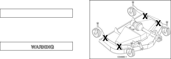
4 - 1003751
WARNING
CRUSHING AND PINCHING HAZARD
Be extremely careful handling various parts of the machine. They are heavy and hands, fingers, feet, and other body parts could be crushed or pinched between tractor and implement.
Operate tractor controls from tractor seat only.
Do not stand between tractor and implement when tractor is in gear.
Make sure parking brake is engaged before going between tractor and implement.
Stand clear of machine while in operation or when it is being raised or lowered.
FAILURE TO FOLLOW THESE
INSTRUCTIONS COULD RESULT IN SERIOUS INJURY OR DEATH. 1003751-A
8 Safety |
MAN0260 (Rev. 1/12/2007) |
|
|
SAFETY & INSTRUCTIONAL DECALS
ATTENTION! BECOME ALERT! YOUR SAFETY IS INVOLVED!
Replace Immediately If Damaged!
WARNING |
5 - 18866 |
WARNING |
|
|
8 - 18865 |
|
|
540 RPM |
|
|
FALLING OFF CAN RESULT IN BEING RUN OVER. |
! " #$ |
18866-D |
|
|
|
|
|
Tractor must be equipped with ROPS (or ROPS CAB) and seat |
|||||
|
|
|
|
|
belt. Keep foldable ROPS systems in “locked up” position at all |
||||||
|
|
|
|
|
|
||||||
|
|
|
|
|
|
times. |
|
|
|
|
|
|
|
|
|
|
|
Buckle Up! Keep seat belt securely fastened. |
|
||||
|
|
|
6 - 18864 |
|
Allow no riders. |
|
|
|
|||
DANGER |
|
RAISED EQUIPMENT CAN DROP AND CRUSH. |
|
||||||||
|
|
|
|
||||||||
|
|
|
|
Before working underneath, follow all instructions and safety rules in |
|||||||
|
|
|
|
operator’s manual and securely block up all corners of equipment |
|||||||
|
|
|
|
|
|
||||||
|
|
|
|
|
|
with jack stands. |
|
|
|
||
|
|
|
|
|
|
Securely blocking prevents equipment dropping from hydraulic leak- |
|||||
|
|
|
|
|
|
down, hydraulic system failures or mechanical component failures. |
|||||
|
|
|
|
|
FALLING OFF OR FAILING TO BLOCK SECURELY CAN |
||||||
|
|
|
|
|
RESULT IN SERIOUS INJURY OR DEATH. |
18865--C |
|||||
ROTATING DRIVELINE |
|
|
|
|
|
|
|
|
|
|
|
CONTACT CAN CAUSE DEATH |
|
|
|
|
|
|
|
|
|
||
KEEP AWAY! |
|
|
|
9 - 1004114 |
|
|
|
|
|
|
|
DO NOT OPERATE WITHOUT - |
|
|
|
|
|
|
|
|
|||
|
|
|
|
|
|
|
|
|
|
||
All driveline guards, tractor and |
|
|
|
|
DANGER |
|
|
|
|
||
equipment shields in place |
|
|
|
|
|
|
|
|
|||
|
|
|
If shaft connection is visible, shield |
|
|
||||||
|
|
|
|
|
|
||||||
Drivelines securely attached at both ends |
|
is missing. Replace shield before |
10 - 33347 |
|
|||||||
Driveline guards that turn freely on |
|
|
|
operating equipment. |
|
1004114 |
|
|
|||
|
|
|
|
|
|
|
|
|
|
|
|
driveline |
18864-C |
|
|
|
|
|
|
|
|
||
|
|
|
|
|
|
|
|
||||
|
|
|
|
|
|
|
|
|
|
||
|
|
|
|
BE CAREFUL! |
|
|
|
|
|||
7 - 1002423 |
|
|
|
Use a clean, damp cloth to |
|
|
|||||
|
|
|
clean safety |
decals. |
Avoid |
|
|
||||
WARNING |
|
|
|
|
|
||||||
|
|
|
spraying too close to decals |
|
|||||||
|
|
|
|
when |
using |
a |
pressure |
||||
TO AVOID SERIOUS INJURY OR DEATH: |
|
|
|
||||||||
|
washer; |
high-pressure |
water |
|
|||||||
Read Operator's Manual before operating, |
|
||||||||||
|
can enter through very small |
|
|
||||||||
servicing or repairing equipment. Follow all |
|
|
|
||||||||
safety rules and instructions. (Manuals are |
|
scratches or under edges of |
|
||||||||
available from your selling dealer.) |
|
|
|
||||||||
Never allow riders. |
|
|
|
decals causing them to peel |
|
|
|||||
Keep bystanders away from equipment during |
|
or come off. |
|
|
|
|
|
|
|||
operation. |
|
|
|
Replacement |
safety |
decals |
|
|
|||
Operate from tractor seat only. |
|
|
|
|
|
||||||
Keep all shields in place and in good condition. |
|
can be ordered free from your |
|
|
|||||||
Lower equipment to ground, stop engine, |
|
Woods dealer. To locate your |
|
|
|||||||
remove key and set brake before dismounting |
|
|
|
||||||||
tractor. |
|
|
|
nearest |
dealer, |
check |
the |
|
|||
Never allow children or untrained persons to |
|
Dealer |
Locator |
|
at |
|
|||||
operate equipment. |
|
|
|
|
|||||||
|
|
|
www.WoodsEquipment.com, |
||||||||
Do not transport towed or semi-mounted units |
|
|
33347E |
||||||||
|
|
|
|||||||||
over 20 MPH. |
|
|
|
or in the United |
States |
and |
|
||||
FAILURE TO FOLLOW THESE INSTRUCTIONS |
|
Canada call 1-800-319-6637. |
|||||||||
CAN RESULT IN INJURY OR DEATH. |
|
1002423-B |
|
|
|||||||
|
|
|
|
|
|
|
|
|
|||
MAN0260 (Rev. 1/12/2007) |
Safety 9 |
|
|
OPERATION
The operator is responsible for the safe operation of the mower. The operator must be properly trained. Operators should be familiar with the mower, the tractor, and all safety practices before starting operation. Read the safety rules and safety decals on page 5 through page 9.
This mower is designed for lawn and grass mowing. It is not designed for rough conditions or heavy weed mowing. It is equipped with suction type blades for best results in lawn mowing.
Recommended mowing speed for most conditions is from 2 to 5 mph.

Full chain shielding, designed to reduce the possibility of thrown objects, must be installed when operating in populated areas or other areas where thrown objects could injure people or damage property. If this machine is not equipped with full chain shielding, operation must be stopped when anyone comes within several hundred feet.

Never allow children or untrained persons to operate equipment.
Keep bystanders away from equipment.
Make sure spring-activated locking pin or collar slides freely and is seated firmly in tractor PTO spline groove.
Operate tractor PTO at 540 RPM. Do not exceed.
Before working underneath, carefully read Operator’s Manual instructions, disconnect driveline, raise mower, securely block up all corners with jackstands, and check stability. Secure blocking prevents equipment from dropping due to hydraulic leak down, hydraulic system failures, or mechanical component failures.
Keep all persons away from operator control area while performing adjustments, service, or maintenance.
 CAUTION
Stop power unit and implement immediately upon striking an obstruction. Dismount power unit,
using proper procedure. Inspect and repair any damage before resuming operation.
Always wear relatively tight and belted clothing to avoid entanglement in moving parts. Wear sturdy, rough-soled work shoes and protective equipment for eyes, hair, hands, hearing, and head; and respirator or filter mask where appropriate.
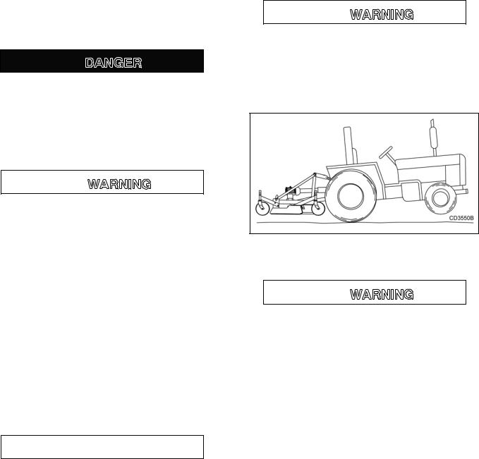
Tractor Stability

A minimum 25% of tractor and equipment weight must be on the tractor front wheels when attachments are in transport position. Without this weight, tractor could tip over, causing personal injury or death. The weight may be attained with a loader. Weigh the tractor and equipment. Do not estimate.
Figure 1. Tractor Stability
Attach Mower to Tractor

Make sure spring-activated locking pin or collar slides freely and is seated firmly in tractor PTO spline groove.
The standard 1-3/8" 6B-spline driveline with a QD yoke is used to connect the mower to the tractor.
1.Attach the mower hitch pins to the lower tractor lift arms and secure.
2.Attach tractor top link (1), Figure 2, to mower top link bracket attachment point (A). Connect the driveline to the tractor PTO shaft.
3.Attach tether chain to tractor drawbar (Figure 3).
4.Adjust the tractor lower 3-point arm anti-sway devices to prevent mower from swinging side to side during transport.
10 Operation |
MAN0260 (Rev. 1/12/2007) |
|
|
1. Tractor Top Link
A.Mower Top Link Attachment Point
B.Mower Hitch Pin
Figure 2. Attachment Points
Tether Chain
CM906
Figure 3. Attach Mower to Tractor
Adjust Cutting Height

Keep all persons away from operator control area while performing adjustments, service, or maintenance.
IMPORTANT
■ Avoid low cutting heights. Striking the ground with blades produces one of the most damaging shock loads a mower can encounter. Allowing blades to contact ground repeatedly will cause damage to mower and drive.
1.Level mower from side to side. Check by measuring distance from mower frame to the ground at each deck rail.
2.Verify that the same amount of spacers are under all caster arms.
3.Control cutting height by adjusting front and rear caster wheels.
4.To raise rear of mower, move caster adjustment spacers under rear caster arms.
5.To raise front of mower, move spacers under front caster wheel arms.
Table 1: Cutting Height Chart
Spacers Required Under
Caster Arm Pivot Tube
Cut Height |
1/2" Spacer |
1" Spacer |
|
|
|
1" |
0 |
0 |
|
|
|
1-1/2" |
1 |
0 |
|
|
|
2" |
0 |
1 |
|
|
|
2-1/2" |
1 |
1 |
|
|
|
3" |
0 |
2 |
|
|
|
3-1/2" |
1 |
2 |
|
|
|
4" |
0 |
3 |
|
|
|
4-1/2" |
1 |
3 |
|
|
|
Tractor Top Link Adjustment
When the cutting height is set, adjust tractor top link until mower top link attachment point (A), Figure 4, is aligned vertically with mower hitch pin (B). The front tires of the mower will lift off the ground before the rear tires when the unit is raised. This will allow the mower to follow the ground contour.
A.Mower top link attachment point
B.Mower hitch pin
C.Tractor top link
D.Mower hitch plate attach-
ment point
Figure 4. Top Link Adjustment
RDC54 Only
The RDC54 has two mower hitch plate attachment points (D). It may be necessary to change the mower
MAN0260 (Rev. 1/12/2007) |
Operation 11 |
|
|
hitch plate attachment point to obtain proper tire clearance and/or lift height.
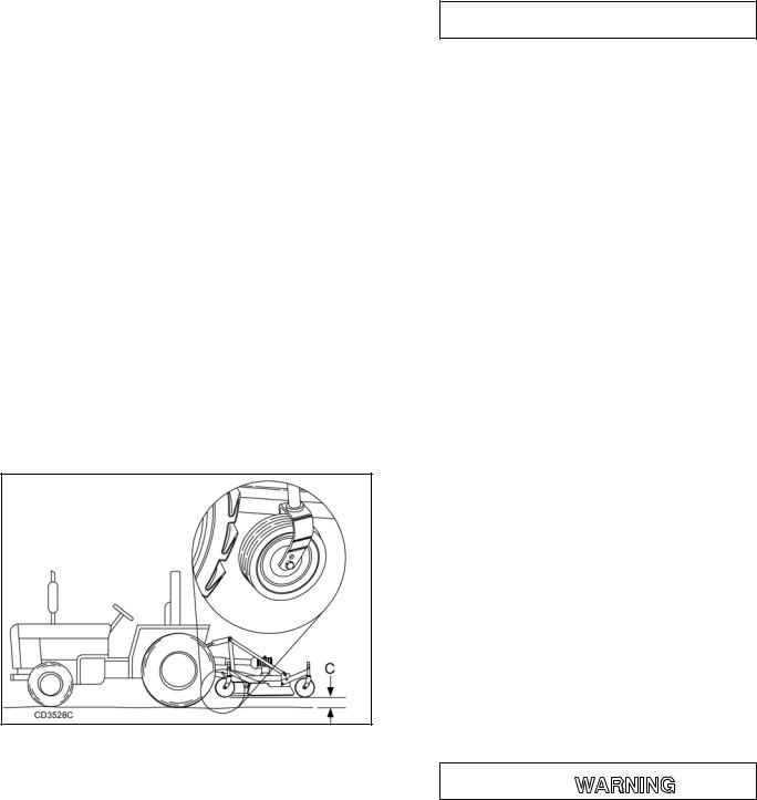
Front Caster Wheel Interference Check
IMPORTANT
■ Do not operate tractor and mower until this interference check has been performed. If you change tractors, you must perform the check for that mounting.
Perform this check with all of the spacers and springs above the caster wheel arm. This will place the caster wheels in their highest position and provide the lowest cutting height for the mower.
1.Raise mower with tractor hydraulics to 16" at dimension C, Figure 5, or maximum height of tractor lift, whichever is less.
2.Pivot both front caster wheels forward and check that there is clearance between caster wheels and tractor tires.
3.If there is interference on RDC54 model, adjust mower hitch plate point as shown in Figure 4. On model RD60 and RD72, the hitch plate is not adjustable; see tractor operator’s manual and adjust tractor wheels accordingly.
Figure 5. Front Caster Wheel Interference Check
Front Roller (Optional)
The caster wheels effectively reduce scalping in most cases. However, you may encounter areas where the caster wheels and/or side skids drop into depressions and allow center of the mower to contact ground and scalp. An optional front roller may be installed to minimize scalping. See page 40.
Operating Technique
 CAUTION
Stop power unit and implement immediately upon striking an obstruction. Dismount power unit, using proper procedure. Inspect and repair any damage before resuming operation.
Power for operating the mower is supplied by the tractor PTO. Operate PTO at 540 rpm. Know how to stop tractor and mower quickly in an emergency.
If mower becomes plugged causing belt to slip for over two seconds, follow these steps:
1.Maneuver equipment into a previously cut area and allow mower to clear accumulated material.
2.Continue running at least two minutes, allowing pulleys to cool. Stopping the mower when in contact with a very hot pulley will bake and ruin belt.
Proper ground speed will depend upon the terrain, the height, and type and density of material to be cut.
Normally, ground speed will range from 2 to 5 mph. Tall dense material should be cut at a low speed; thin medium-height material can be cut at a faster ground speed. Always operate tractor PTO at 540 rpm to maintain proper blade speed and produce a clean cut.
Under certain conditions, tractor tires may roll some grass down and prevent it from being cut at the same height as the surrounding area. When this occurs, reduce your ground speed, but maintain PTO at 540 rpm. The lower ground speed will permit grass to partially rebound.
In general, lower cutting heights give a more even cut and leave less tire tracks. However, it is better to cut grass frequently rather than too short. Short grass deteriorates rapidly in hot weather and invites weed growth during growing seasons. Follow local recommendations for the suitable cutting height in your area.
Operating Tips

Inspect and clear area of stones, branches, or other hard objects that might be thrown, causing injury or damage.
Extremely tall material should be cut twice. Set mower at a higher cutting height for the first pass. Then cut at desired height, 90 degrees to the first pass. Remember, sharp blades produce cleaner cuts and require less power.
Analyze area to be cut to determine the best procedure. Consider height and type of grass and terrain
12 Operation |
MAN0260 (Rev. 1/12/2007) |
|
|

type: hilly, level, or rough. Plan your mowing pattern to travel straight forward whenever possible. Mow with uncut grass to the right. This will distribute the clippings over the cut area.
Uneven Terrain

Do not operate or transport on steep slopes.
Do not stop, start, or change directions suddenly on slopes.
Use extreme care and reduce ground speed on slopes and rough terrain.
Watch for hidden hazards on the terrain during operation.
Pass diagonally through sharp dips and avoid sharp drops to prevent hanging up tractor and mower. Practice will improve your skills in maneuvering rough terrain.
Removing Mower from Tractor - Storage
Follow cleaning procedure, page 17.
1.Disengage tractor PTO and raise mower with the 3-point hitch.
2.Disconnect mower driveshaft from tractor PTO.
3.Collapse driveshaft as far as possible and store it in PTO hanger bracket to prevent ground contact.
4.Place blocks under mower side skids. Lower mower onto blocks, disconnect mower from tractor 3-point hitch, and carefully drive tractor away from mower.

Keep children and bystanders away from storage area.
Figure 6. Mower Storage Position
OWNER PRE-OPERATION CHECK LIST
(OWNER'S RESPONSIBILITY)
___ |
Review and follow all safety rules and safety |
|
decal instructions on page 5 through page 9. |
___ |
Check that all safety decals are installed and in |
|
good condition. Replace if damaged. |
___ |
Check that all shields and guards are properly |
|
installed and in good condition. Replace if dam- |
|
aged. |
___ |
Check that chain shielding is in good condition |
|
and replace any damaged chain links. |
___ |
Check that all hardware and cotter pins are prop- |
|
erly installed and secured. |
___ |
Check to ensure blades are sharp, in good condi- |
|
tion, and installed correctly. Replace if damaged. |
___ |
Check that equipment is properly and securely |
|
attached to tractor. |
___ |
Make sure driveline spring-activated locking pin |
|
or collar slides freely and is seated firmly in trac- |
|
tor PTO spline groove. |
___ |
Make sure the driveline guards and tether chains |
|
are in good condition. Guards must rotate freely |
|
on driveline. Fasten tether chains to the tractor |
|
and the equipment as instructed. |
___ |
Inspect area and remove stones, branches or |
|
other hard objects that might be thrown, causing |
|
injury or damage. |
___ |
Do not allow riders. |
___ Check all lubrication points and grease as instructed in “Lubrication Information” on page 14 & page 15. Make sure the PTO slip joint is lubricated and that the gearbox fluid levels are correct.
___ Set tractor PTO at correct rpm for your equipment.
___ Make sure tractor ROPS or ROPS cab and seat belt are in good condition. Keep seat belt securely fastened during operation.
___ Before starting engine, operator must be in tractor seat with seat belt fastened. Place transmission in neutral or park, engage brake, and disengage tractor PTO.
MAN0260 (Rev. 1/12/2007) |
Operation 13 |
|
|
OWNER SERVICE
The information in this section is written for operators who possess basic mechanical skills. If you need help, your dealer has trained service technicians available. For your protection, read and follow the safety information in this manual.
 CAUTION
Always wear relatively tight and belted clothing to avoid entanglement in moving parts. Wear sturdy, rough-soled work shoes and protective equipment for eyes, hair, hands, hearing, and head; and respirator or filter mask where appropriate.

Never allow children or untrained persons to operate equipment.
Keep bystanders away from equipment.
Before working underneath, carefully read Operator’s Manual instructions, disconnect driveline, raise mower, securely block up all corners with jackstands, and check stability. Secure blocking prevents equipment from dropping due to hydraulic leak down, hydraulic system failures, or mechanical component failures.
Keep all persons away from operator control area while performing adjustments, service, or maintenance.
Make sure spring-activated locking pin or collar slides freely and is seated firmly in tractor PTO spline groove.
Operate tractor PTO at 540 RPM. Do not exceed.
BLOCKING METHOD
Do not work underneath mower unless it is properly attached to the tractor and blocked securely. When properly attached, the unit will be anchored to minimize front to rear movement.
Raise mower completely, set tractor brakes, turn engine off, remove key, block tractor wheels front and rear, and disconnect mower driveline from tractor.
The only approved blocking devices for this mower are jackstands with a load rating of 1000 pounds or more. One jackstand under each corner of the mower (four total) must be installed before working underneath this unit.
When blocking, you must consider overall stability of the unit. Just blocking under the unit will not ensure your safety. The working surface must be level and
solid to support the loaded weight of the jackstands. Test jackstand stability before working under any portion of the mower.
Figure 7. Jackstand Placement
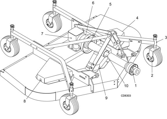
Lubrication Information
Do not let excess grease collect on or around parts, particularly when operating in sandy areas.
Figure 8 shows the lubrication points. The accompanying chart gives the frequency of lubrication in operating hours, based on normal operating conditions.
Severe or unusual conditions may require more frequent lubrication. Some reference numbers have more than one location; be sure you lubricate all locations.
Use a lithium grease of #2 consistency with a MOLY (molybdenum disulfide) additive for all locations. Be sure to clean fittings thoroughly before attaching grease gun. When applied according to the lubrication chart, one good pump of most guns is sufficient.
Use SAE 90W gear lube in the gearbox. Fill to plug on side of gearbox.
Check gearbox daily for evidence of leakage at both seals and the gasket between the housing and cover. If leakage is noted, repair immediately. There may be a small amount of lube emitted from the vent plug; this is not considered leakage.
Overfilling the gearbox will cause the excess gear lube to blow out vent plug and ruin the belt.
Driveshaft Lubrication
Lubricate the driveshaft slip joint every 40 operating hours. Failure to maintain proper lubrication could result in damage to U-joints, gearbox, and driveshaft.
1. Lower mower to ground.
14 Owner Service |
MAN0260 (Rev. 1/12/2007) |
|
|
2.Remove front half of driveshaft.
3.Apply grease all around and along inner shaft.
4.Reassemble driveshaft halves.
5.Raise and lower mower several times to distribute grease.
SERVICE BELT
Replace Belt
One of the major causes of belt failure is improper installation. Before installing a new belt, check the following:
1.Check pulley shafts and bearings for wear.
2.Check pulley grooves for cleanliness.
3.Make sure spindles turn freely and without wobble.
Ref |
Description |
Frequency |
No. |
|
|
1 |
Front U-Joint |
8 Hours |
2 |
Caster Wheel (Four wheels) |
8 Hours |
3 |
Caster Pivot (Four wheels) |
8 Hours |
4 |
Left Spindle (Access through hole) |
40 Hours |
5 |
Shield Bearings |
8 Hours |
6 |
Rear U-Joint |
8 Hours |
7 |
Gearbox (Fill to center of horizontal shaft with |
Check Daily |
|
SAE 80W or 90W gear lube) |
For Leakage |
8 |
Right Spindle (Access through hole) |
40 Hours |
9 |
Center Spindle (Access through hole) |
40 Hours |
10 |
Slip Joint |
40 Hours |
|
|
|
|
Figure 8. Lubrication Points & Chart |
|
MAN0260 (Rev. 1/12/2007) |
Owner Service 15 |
|
|
 Loading...