


Manual Lift Models:
MX54 & MX61
PowerTilt™ Models:
MX54T & MX61T
MAN0253 |
(Rev. 6/8/2010) |
 OPERATOR'S MANUAL

TO THE DEALER:
Assembly and proper installation of this product is the responsibility of the Woods® dealer. Read manual instructions and safety rules. Make sure all items on the Dealer’s Pre-Delivery and Delivery Check Lists in the Operator’s Manual are completed before releasing equipment to the owner.
The dealer must complete the online Product Registration form at the Woods Dealer Website which certifies that all Dealer Check List items have been completed. Please contact your dealer to complete this form. Dealers can register all Woods product at dealer.WoodsEquipment.com under Product Registration.
Failure to register the product does not diminish customer’s warranty rights.
TO THE OWNER:
Read this manual before operating your Woods equipment. The information presented will prepare you to do a better and safer job. Keep this manual handy for ready reference. Require all operators to read this manual carefully and become acquainted with all adjustment and operating procedures before attempting to operate. Replacement manuals can be obtained from your dealer. To locate your nearest dealer, check the Dealer Locator at www.WoodsEquipment.com, or in the United States and Canada call 1-800-319-6637.
The equipment you have purchased has been carefully engineered and manufactured to provide dependable and satisfactory use. Like all mechanical products, it will require cleaning and upkeep. Lubricate the unit as specified. Observe all safety information in this manual and safety decals on the equipment.
For service, your authorized Woods dealer has trained mechanics, genuine Woods service parts, and the necessary tools and equipment to handle all your needs.
Use only genuine Woods service parts. Substitute parts will void the warranty and may not meet standards required for safe and satisfactory operation. Record the model number and serial number of your equipment in the spaces provided:
Model: _______________________________ |
Date of Purchase: _____________________ |
Serial Number: (see Safety Decal section for location) ____________________________________
Provide this information to your dealer to obtain correct repair parts.
Throughout this manual, the term NOTICE is used to indicate that failure to observe can cause damage to equipment. The terms CAUTION, WARNING, and DANGER are used in conjunction with the Safety-Alert Symbol (a triangle with an exclamation mark) to indicate the degree of hazard for items of personal safety.
|
|
|
|
2 Introduction |
Gen’l (Rev. 3/5/2010) |
||
|
|
|
|
TABLE OF CONTENTS
INTRODUCTION . . . . . . . . . . . . . . . . . . . . . . . . . . . . . . . . . . . . . . . . . . . . . . 2 SPECIFICATIONS . . . . . . . . . . . . . . . . . . . . . . . . . . . . . . . . . . . . . . . . . . . . . 4 GENERAL INFORMATION . . . . . . . . . . . . . . . . . . . . . . . . . . . . . . . . . . . . . . 4 SAFETY RULES . . . . . . . . . . . . . . . . . . . . . . . . . . . . . . . . . . . . . . . . . . . . . . 5 SAFETY DECALS . . . . . . . . . . . . . . . . . . . . . . . . . . . . . . . . . . . . . . . . . . . . . 7 OPERATION . . . . . . . . . . . . . . . . . . . . . . . . . . . . . . . . . . . . . . . . . . . . . . . . . 9 SERVICE . . . . . . . . . . . . . . . . . . . . . . . . . . . . . . . . . . . . . . . . . . . . . . . . . . . 16 ASSEMBLY INSTRUCTIONS . . . . . . . . . . . . . . . . . . . . . . . . . . . . . . . . . . . 22 DEALER CHECK LISTS . . . . . . . . . . . . . . . . . . . . . . . . . . . . . . . . . . . . . . . 30 INDEX TO PARTS LISTS . . . . . . . . . . . . . . . . . . . . . . . . . . . . . . . . . . . . . . 31 BOLT TORQUE CHART . . . . . . . . . . . . . . . . . . . . . . . . . . . . . . . . . . . . . . . 47 BOLT SIZE CHART & ABBREVIATIONS . . . . . . . . . . . . . . . . . . . . . . . . . . 48 INDEX . . . . . . . . . . . . . . . . . . . . . . . . . . . . . . . . . . . . . . . . . . . . . . . . . . . . . 49 PRODUCT WARRANTY . . . . . . . . . . . . . . . . . . . . . . . . . . . . . . . . . . . . . . . 50 REPLACEMENT PARTS WARRANTY . . . . . . . . . . . . INSIDE BACK COVER
!LEA EL INSTRUCTIVO!
Si no lee Ingles, pida ayuda a alguien que si lo lea para que le traduzca las medidas de seguridad.
MAN0253 (Rev. 12/22/2007) |
Introduction 3 |
|
|

SPECIFICATIONS
|
MX54 |
MX54T |
MX61 |
MX61T |
|
|
(with |
|
(with |
|
|
PowerTilt™) |
|
PowerTilt™) |
|
|
|
|
|
Cutting Width |
54" |
54" |
61" |
61" |
|
|
|
|
|
Cutting Height Range |
1- 5" |
1- 5" |
1- 5" |
1- 5" |
|
|
|
|
|
Blade RPM (Approximate) |
3,635 |
3,635 |
3,328 |
3,328 |
|
|
|
|
|
Blade Tip Speed (Approximate Ft./Min.) |
17,800 |
17,800 |
18,300 |
18,300 |
|
|
|
|
|
Blade Spindles |
3 |
3 |
3 |
3 |
|
|
|
|
|
Number of Blades |
3 |
3 |
3 |
3 |
|
|
|
|
|
Caster Wheels |
11 x 4.0 x 5 |
11 x 4.0 x 5 |
11 x 4.0 x 5 |
11 x 4.0 x 5 |
|
|
|
|
|
Mower Frame Thickness |
10 Gauge |
10 Gauge |
10 Gauge |
10 Gauge |
|
|
|
|
|
Weight |
429 lbs |
429 lbs |
453 lbs |
453 lbs |
|
|
|
|
|
Deck Angle (PowerTilt) |
N/A |
55° |
N/A |
55° |
|
|
|
|
|
Power Unit and Deck Length |
103.5" |
103.5" |
108.5" |
108.5" |
(Down Position, Wheels Turned Inward; FZ23B, |
|
|
|
|
FZ28K) |
|
|
|
|
|
|
|
|
|
Power Unit and Deck Length |
N/A |
95.5" |
N/A |
100.5" |
(Deck Raised; FZ23B, FZ28K) |
|
|
|
|
|
|
|
|
|
Power Unit and Deck Length |
106.5" |
106.5" |
111.5" |
111.5" |
(Down Position, Wheels Turned Inward; FZ25D) |
|
|
|
|
|
|
|
|
|
Power Unit and Deck Length |
N/A |
98" |
N/A |
103" |
(Deck Raised; FZ25D) |
|
|
|
|
|
|
|
|
|
GENERAL INFORMATION

Some illustrations in this manual show the equipment with safety shields removed to provide a better view. This equipment should never be operated with any necessary safety shielding removed.
The purpose of this manual is to assist you in operating and maintaining your Mow’n Machine Mower. Read it carefully. It furnishes information and instructions that will help you achieve years of dependable performance. These instructions have been compiled from extensive field experience and engineering data.
Some information may be general in nature due to unknown and varying operating conditions. However, through experience and these instructions, you should be able to develop procedures suitable to your particular situation.
The illustrations and data used in this manual were current at the time of printing but, due to possible inline production changes, your machine may vary slightly in detail. We reserve the right to redesign and change the machines as may be necessary without notification.
Throughout this manual, references are made to right and left directions. These are determined by standing behind the equipment facing the direction of forward travel. Blade rotation is clockwise as viewed from the top of the mower.
4 Introduction |
MAN0253 (Rev. 12/22/2007) |
|
|

SAFETY RULES
ATTENTION! BECOME ALERT! YOUR SAFETY IS INVOLVED!
Safety is a primary concern in the design and manufacture of our products. Unfortunately, our efforts to provide safe equipment can be wiped out by an operator’s single careless act.
In addition to the design and configuration of equipment, hazard control and accident prevention are dependent upon the awareness, concern, judgement, and proper training of personnel involved in the operation, transport, maintenance, and storage of equipment.
It has been said, “The best safety device is an informed, careful operator.” We ask you to be that kind of operator.
TRAINING
Safety instructions are important! Read all attachment and power unit manuals; follow all safety rules and safety decal information. (Replacement manuals and safety decals are available from your dealer. To locate your nearest dealer, check the Dealer Locator at www.WoodsEquipment.com, or in the United States and Canada call 1-800-319- 6637.) Failure to follow instructions or safety rules can result in serious injury or death.
If you do not understand any part of this manual and need assistance, see your dealer.
Know your controls and how to stop engine and attachment quickly in an emergency.
Operators must be instructed in and be capable of the safe operation of the equipment, its attachments, and all controls. Do not allow anyone to operate this equipment without proper instructions.
Never allow children or untrained persons to operate equipment.
Data indicates that those operators age 60 years and above are involved in a large percentage of riding mower-related injuries. Those operators should evaluate their ability to operate the riding mower safely enough to protect themselves and others from injury.
PREPARATION
Check that all hardware is properly installed. Always tighten to torque chart specifications unless instructed otherwise in this manual.
Make sure attachment is properly secured, adjusted, and in good operating condition.
Make sure the driveline spring-activated locking collar slides freely and is seated firmly in power unit PTO groove. Make sure the set screws securely attach driveline to the attachment gearbox shaft.
Remove accumulated debris from this equipment, power unit, and engine to avoid fire hazard.
Make sure all safety decals are installed. Replace if damaged. (See Safety Decals section for location.)
Make sure shields and guards are properly installed and in good condition. Replace if damaged.
Be sure either the discharge chute, mulching end cap, or complete vacuum attachment is installed and in good condition. Replace if damaged.
Inspect and clear area of stones, branches, or other hard objects that might be thrown, causing injury or damage.
OPERATION
Keep bystanders away from equipment.
Do not mow on wet grass.
Never direct discharge toward people, animals, or property.
Keep children out of the mowing area and under the watchful care of a responsible adult other than the operator.
Do not operate or transport equipment while under the influence of alcohol or drugs.
Operate only in daylight or good artificial light.
Keep hands, feet, hair, and clothing away from equipment while engine is running. Stay clear of all moving parts.
Never allow riders on power unit or attachment.
Installation of a grasscatcher assembly will reduce the stability and maneuverability of the Mow'n Machine when operating on sloping terrain.
Do not drive or operate mower in optional tilt-up position. Power unit is not stable enough and lifting device can be damaged or fail. A tilted deck also increases the chance of thrown objects and blade contact.
Do not operate power unit with attachment removed. Attachment is required for power unit stability.
(Safety Rules continued on next page)
MM DT/MX Mower Safety Rules (Rev. 3/10/2007)
Safety 5

SAFETY RULES
ATTENTION! BECOME ALERT! YOUR SAFETY IS INVOLVED!
(Safety Rules continued from previous page)
MAINTENANCE
Before performing any service or maintenance, lower attachment to ground, turn off power unit engine, remove key, and disconnect battery ground cable (negative -).
Block mower securely before working underneath.
Do not modify or alter or permit anyone else to modify or alter the equipment or any of its components in any way.
Do not work under elevated mower deck unless lock-up mechanism is in good condition and fully engaged as instructed. Replace if damaged.
Make sure attachment is properly secured, adjusted, and in good operating condition.
Keep all persons away from operator control area while performing adjustments, service, or maintenance.
Frequently check blades. They should be sharp, free of nicks and cracks, and securely fastened.
Your dealer can supply genuine replacement blades. Substitute blades may not meet original equipment specifications and may be dangerous.
Do not handle blades with bare hands. Careless or improper handling may result in serious injury.
Tighten all bolts, nuts, and screws to torque chart specifications. Check that all cotter pins are installed securely to ensure equipment is in a safe condition before putting unit into service.
Make sure all safety decals are installed. Replace if damaged. (See Safety Decals section for location.)
Make sure shields and guards are properly installed and in good condition. Replace if damaged.
Use care when installing or removing belt from spring-loaded idler. Springs store energy when extended and, if released suddenly, can cause personal injury.
STORAGE
Block equipment securely for storage.
Follow manual instructions for storage.
Keep children and bystanders away from storage area.
6 Safety
MM DT/MX Mower Safety Rules (Rev. 3/10/2007)

SAFETY & INSTRUCTIONAL DECALS
ATTENTION! BECOME ALERT! YOUR SAFETY IS INVOLVED!
Replace Immediately If Damaged!
4 - PN 18869
 DANGER
SHIELD MISSING
DO NOT OPERATE - PUT SHIELD ON
MX54 & MX61
18869-B
1 - SERIAL NUMBER PLATE |
9 - PN 72672 |
|
|
|
WARNING |
|
|
|
THROWN OBJECT HAZARD CAN RESULT IN |
|
MODEL NO. |
SERIAL NO. |
SERIOUS INJURY OR DEATH. |
|
|
|
NEVER OPERATE WITHOUT DISCHARGE |
|
|
Woods Equipment Company |
CHUTE OR ENTIRE GRASSCATCHER |
|
|
SYSTEM IN PLACE. |
72672 |
|
|
Oregon, Illinois, U.S.A. |
||
|
|
|
|
2 - PN 78207 |
|
3 - PN 72426 |
|
|
|
|
|
 DANGER
KEEP AWAY!
Blade contact or thrown objects can cause serious injury or death.
Never operate without the plastic, hinged discharge chute, mulching end cap, or entire grasscatcher in place.
78207-A |
(Safety Decals continued on next page) |
MAN0253 (Rev. 3/10/2007) |
Safety 7 |
|
|
SAFETY & INSTRUCTIONAL DECALS
ATTENTION! BECOME ALERT! YOUR SAFETY IS INVOLVED!
Replace Immediately If Damaged!
(Safety Decals continued from previous page)
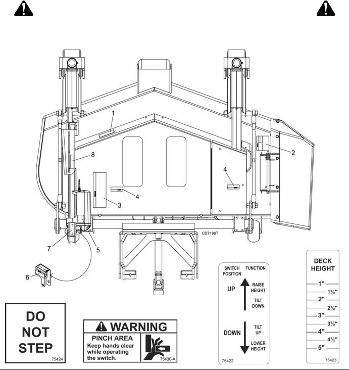
8 - PN 75423
7 - PN 75422
(SN 1100885 & Below)
5 - PN 75424
6 - PN 75430 (SN 1100885 & Below)
BE CAREFUL!
Use a clean, damp cloth to clean safety decals.
Avoid spraying too close to decals when using a pressure washer; high-pressure water can enter through very small scratches or under edges of decals causing them to peel or come off.
Replacement safety decals can be ordered free from your Woods dealer. To locate your nearest dealer, check the Dealer Locator at www.WoodsEquipment.com, or in the United
States and Canada call 1-800-319-6637.
8 Safety |
MAN0253 (Rev. 12/22/2007) |
|
|
OPERATION

Make sure the driveline spring-activated locking collar slides freely and is seated firmly in power unit PTO groove. Make sure the set screws securely attach driveline to the attachment gearbox shaft.
Do not operate power unit with attachment removed. Attachment is required for power unit stability.
 CAUTION
Always wear relatively tight and belted clothing to avoid getting caught in moving parts. Wear sturdy, rough-soled work shoes and protective equipment for eyes, hair, hands, hearing, and head; and respirator or filter mask where appropriate.
ATTACHING MOWER TO POWER UNIT
NOTICE
■ The power unit must comply with counterweight requirements before attaching to power unit.
1.Place power unit and mower on a level surface.
2.Rotate parking stand to the down position so deck is resting on the parking stand wheel.
3.Center the power unit behind mower as close as possible. Shut off engine.
4.Open dump valves on both hydraulic pumps to allow power unit to be moved by hand. See Mow’n Machine power unit manual for location of dump valves.
NOTE: If you have a PowerTilt™ model, the wiring harness must be connected before raising or lowering the deck to align the arm with the mounting bracket. See Connect Wiring Harness - PowerTilt™ Units MXT Deck SN 1100885 and below, page 24 for instructions.
5.Use the height adjustment handle (or height adjustment switch on PowerTilt models) to raise or lower rear pivot lift arm and align arm with mounting brackets.
6.Attach rear pivot lift arm in desired power unit mounting bracket holes and connect with springloaded pins. See Figure 1 for hole locations.
7.Attach driveline from deck to PTO shaft on power unit.
8.Attach weight transfer chains to right and left weight transfer brackets on rear pivot lift arm.
NOTE: Stepping on the weight transfer arms with your foot will make attaching chains easier.
9.Install flat washers and safety pins in right and left weight transfer brackets to secure chains into position.
10.Close power unit hydraulic pump dump valves.
11.After deck is attached to power unit, raise deck high enough and rotate parking stand into the storage position.
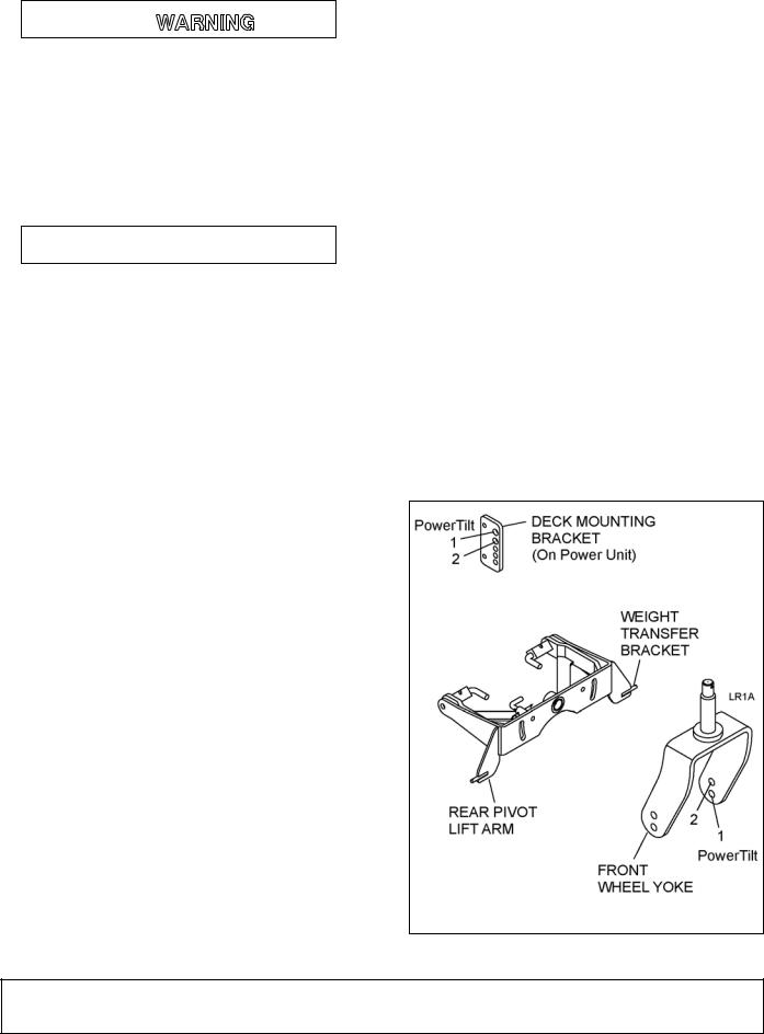
NOTE: Attach rear pivot lift arm in hole position 1 on deck mounting brackets when front wheels are in hole 1 on front wheel yoke. This will put the deck in the high cut range, (2 to 5 inches - manual, 1-1/4 to 5-1/2 inches - PowerTilt™). Attach weight transfer chains to weight transfer brackets using four links. Use PowerTilt™ in hole position 1 shown in Figure 1.
NOTE: Attach rear pivot lift arm in hole position 2 on deck mounting brackets when front wheels are in hole 2 on front wheel yoke. This will put the deck in the low cut range, (1 to 4 inches). Attach weight transfer chains to weight transfer brackets using five links.
Figure 1. Mounting Hole Location
(Rev 1/7/2010)
MAN0253 (Rev. 3/10/2007)
Operation 9
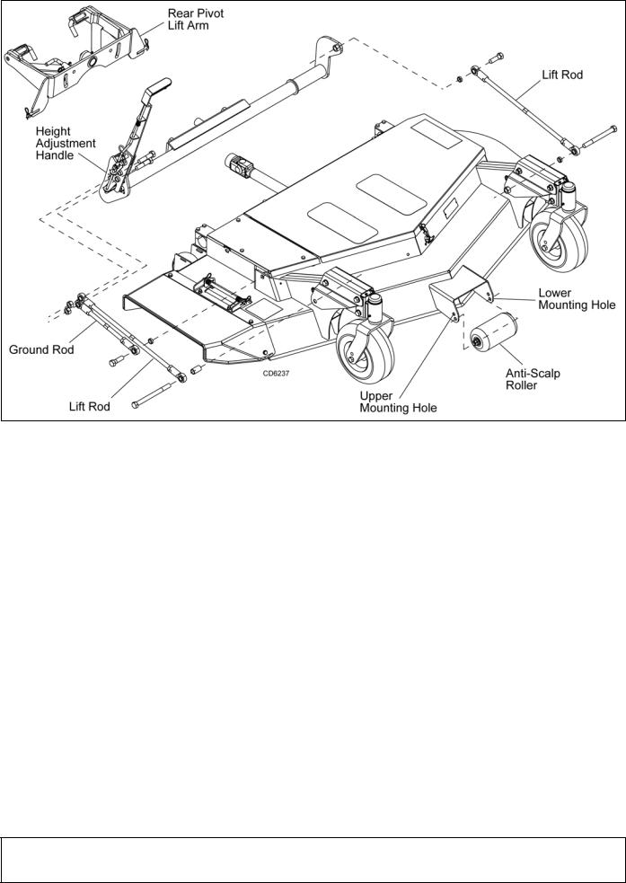
Figure 2. Manual Height Adjustment Linkage - MX54 / MX61
CUTTING HEIGHT ADJUSTMENT
(Figure 2 & Figure 4)
1.Place power unit and mower on a level surface.
2.Make sure power unit tire pressure is set equally on both sides. Improper pressure will adversely affect steering control, traction and mower cutting height.
Standard Front: |
12 psi |
Drive Tire |
Rear: |
18 psi |
Rear Caster |
Front: |
45 psi |
Deck Caster |
3.Cutting height is manually adjusted on the MX54 & MX61 models by moving the height adjustment handle forward to lower the cutting height and rearward to raise the cutting height. For MX54T & MX61T models, see PowerTilt™ Operation.
4.In the high cut range, the caster wheel assembly should be bolted through the lower hole in the caster fork. Anti-scalp rollers should be installed in the lower mounting hole. Use this range for PowerTilt™ decks.
5.In the low cut range, the caster wheel assembly should be bolted through the upper hole in the
caster fork. Anti-scalp rollers should be installed in the upper mounting hole.
6.When the caster wheels are moved to a different hole in the fork, it will be necessary to move the rear pivot lift arm to the corresponding hole in the power unit mounting brackets. See Figure 1.
7.If cut height does not correspond to the respective position for the height adjustment handle on MX54/MX61, the ground rod should be adjusted. See Adjust Mower Deck (Figure 27 & Figure 29), page 26 and page 28. For MX54T/MX61T models, the cut height is aligned with the height decal.
PowerTilt™ Operation (Figure 3 & Figure 4)
Turn power unit key to the ON position.
To set cutting height:
1.Activate rocker switch following instruction decal on top of rocker switch mount. Hold switch until deck is in the fully raised position.
2.Activate switch in the opposite direction to lower deck and to choose the desired cutting height.
10 Operation
(Rev. 1/7/2010) MAN0253 (Rev. 3/10/2007)
DP6T
Figure 3. Deck Fully Raised
To tilt deck up:
Activate switch to lower deck and subsequently move deck into fully tilted position. The actuator will make a ratcheting noise at this position.
To untilt deck:
1.Actuate switch in the opposite direction until actuator makes a ratcheting noise and the height gauge indicates 5".
2.Activate switch following instruction decal to lower deck to desired cutting height.
NOTE: Excessive operation of actuator with engine off will drain battery.
NOTE: The micro switch underneath the height gauge prevents the engine from running with the deck in the raised position. The power unit will not move unless the deck is down and the switch lever is depressed. To check that the switch is working properly when the deck is raised, tilt the deck up halfway and move a traction lever out of neutral while sitting in the operator’s seat. This should shut the engine off.
MOWER SIDE-TO-SIDE ADJUSTMENT
(Figure 2 & Figure 4)
Measure a similar spot to the ground on each rear corner of the mower deck. If there is more than an 1/8" difference between sides, adjust lift rods until sides are within 1/8".
MXT Decks
SN
Figure 4. PowerTilt™ Height Adjustment Linkage - MX54T / MX61T
(Rev. 12/22/2007) MAN0253 (Rev. 3/10/2007)
Operation 11
MOWING TIPS

Keep hands, feet, hair, and clothing away from equipment while engine is running. Stay clear of all moving parts.
Keep bystanders away from equipment.
Use extreme care and reduce ground speed on slopes and rough terrain.
Watch for hidden hazards on the terrain during operation.
NOTICE
■ Always operate power unit engine at full throttle when mowing to maintain proper blade speed and produce a clean cut.
1.Before mowing, analyze the area to determine the best mowing procedure. Consider the height, type of grass, and the terrain type (rolling, level or rough).
2.It is better to mow grass more often rather than too short. Short grass deteriorates rapidly in hot weather and invites weed growth during growing seasons. Follow local recommendations for the suitable cutting height in your area.
3.Proper ground speed for mowing will depend on the height, type and density of grass to be cut. Normally, ground speed will range from two to five m.p.h. Tall dense grass should be mowed at low ground speeds, while thin medium-height grass can be cut at a faster ground speed.
4.Extremely tall grass should be cut twice. Cut grass higher on first pass. Cut the second time at desired height and 90° to first pass.
5.When mowing long grass, stop power unit, turn ignition key off, remove key, and disengage PTO. Check for grass wrap around PTO shaft every 30 minutes of operation.
6.Remember, sharp blades produce cleaner cuts and use less power.
7.For side-discharge mowers, mow with uncut grass to the left. This will distribute the clippings over the cut area. Discharging clippings over the uncut area would cause a build-up and could prevent uniform cutting.
8.All side-discharge mowers are shipped with highsuction blades. These blades will give you satisfactory performance in most conditions. If, however, you are operating in sandy areas, you should change to the optional medium-suction blades.
9.In some conditions the high-suction blades may cause a small windrow when used in conjunction
with the optional vacuum attachments; should this occur, install medium-suction blades.
10.When transporting the Mow'n Machine on a trailer, always lower attachment height adjustment lift mechanism to lowest setting to reduce lift loads, which could damage the height adjustment sector.
STORAGE

Do not operate power unit with attachment removed. Attachment is required for power unit stability.
The parking stand can be used to support the rear of the mower deck when not attached to the power unit.
1.Raise the mower deck sufficiently to provide the necessary clearance for rotating the parking stand into position.
2.Carefully remove the weight transfer chains from the rear pivot lift arm.
3.Disconnect driveline and mower attachment arm from power unit.
4.Back power unit away from deck.
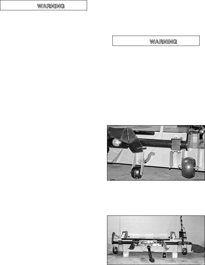
Figure 5. Parking Stand
If deck is to be stored for a long period of time, 4-inch wooden blocks can be used instead of the parking stand. See Figure 6.
Also see Cleaning Before Extended Storage, page 21.
Figure 6. Storage Position
12 Operation |
MAN0253 (Rev. 3/10/2007) |
|
|
TROUBLESHOOTING
MOWING CONDITIONS
PROBLEM |
POSSIBLE CAUSE |
SOLUTION |
|
|
|
|
|
Grass cut higher in center |
Height of mower higher at front than |
Adjust mower height and attitude so that |
|
of swath than at edge |
at the rear |
mower is 3/8-inch lower in the front than the |
|
|
|
rear. See Adjust Mower Deck (Figure 27 & |
|
|
|
Figure 29), page 26 and page 28. |
|
|
Loose blade or blade spindle |
Check hardware. |
|
|
|
|
|
Grass cut lower in center |
Height of mower lower at front than |
Adjust mower height and attitude so that |
|
of swath than at edge |
at the rear |
mower is 3/8-inch lower in the front than the |
|
|
|
rear. See Adjust Mower Deck, page 26. |
|
|
Loose blade or blade spindle |
Check hardware. |
|
|
|
|
|
Streaking conditions in |
Conditions too wet for mowing |
Allow grass to dry before mowing. |
|
swath |
Blades unable to cut that part of |
Slow ground speed of power unit but keep |
|
|
|||
|
grass pressed down by path of |
engine running at full rpm. Cutting lower will |
|
|
deck casters |
help. |
|
|
Dull blades |
Sharpen or replace blades. |
|
|
Loose blade or blade spindle |
Check hardware. |
|
|
|
|
|
Material discharges from |
Material too high and too much |
Reduce ground speed but maintain full engine |
|
mower unevenly; bunches |
material |
rpm, or make two passes over material. Raise |
|
of material along swath |
|
mower for the first pass and lower for the |
|
|
|
second and cut 90 degrees to first pass. |
|
|
Conditions too wet for mowing |
Allow grass to dry before mowing. |
|
|
|
|
|
Uneven cut or poor grass |
Worn, bent or loose blade(s) |
Replace blade(s). Tighten blades. |
|
discharge |
Mower deck not level |
Level mower deck. See Adjust Mower Side- |
|
|
|||
|
|
to-Side, page 27. |
|
|
Buildup of grass, leaves, and trash |
Clean underside of mower. |
|
|
under mower |
|
|
|
Bent spindle shaft |
Replace spindle shaft. |
|
|
Engine speed too slow |
Run throttle at full RPM. |
|
|
Travel speed too fast |
Slow ground speed. |
|
|
Conditions too wet for mowing |
Allow grass to dry before mowing. |
|
|
Low/uneven tire pressure |
Check tires for proper air pressure. |
|
|
Blades improperly installed |
Reinstall blades with sharp edge down. |
|
|
Deck out of adjustment |
Adjust deck. See Adjust Mower Deck, |
|
|
|
page 26. |
|
|
|
|
|
Mower blades will not rotate |
Obstruction in clutch mechanism |
Remove obstruction. |
|
|
Worn/damaged mower PTO belts |
Replace belts. |
|
|
Frozen idler pulley |
Replace pulley. |
|
|
Frozen blade spindle |
Replace spindle. |
|
|
Wiring harness not hooked up |
Connect wiring harness (PowerTilt), page 24. |
|
|
|
|
|
Dandelion seed heads are |
Material is being bent over too far to |
Remove baffle extensions from front baffle. |
|
not being cut |
be cut with the blades |
Reduce ground speed. |
(Continued) |
|
|
|
|
MAN0253 (Rev. 3/10/2007) |
Operation 13 |
|
|
TROUBLESHOOTING
MOWING CONDITIONS (Continued)
PROBLEM |
POSSIBLE CAUSE |
SOLUTION |
|
|
|
Blade fins and /or cutting edge |
Soil conditions are too sandy. |
Install medium lift blades. |
wearing rapidly |
Sand lifted by the blades is |
|
|
wearing them prematurely |
|
Streaking conditions with mulch |
Blades unable to cut grass |
Reduce power unit ground speed but |
kit |
pressed down front caster wheels |
maintain full PTO rpm. Replace mulching |
|
|
blades with standard lift blades to achieve |
|
|
more lift. |
Dribbling cut material from |
Deck unable to discharge the |
Reduce power unit ground speed but |
back of deck in the cut path |
material as quickly as it is being |
maintain full PTO rpm. Clean underside of |
|
cut |
mower. |
Dribbling cut material from |
Cut material is being held under |
Install to medium lift blades. Clean collection |
back of deck in the cut path |
deck instead of being collected by |
system. |
with the grass collection |
the vac |
|
system installed |
|
|
|
|
|
BELT CONDITIONS
Belt slippage |
Mower overloading; Material too |
Reduce power unit ground speed but |
|
tall or heavy |
maintain full PTO rpm. Cut material twice, |
|
|
one high pass and then mow at desired |
|
|
height. Cut 90 degrees to first pass. |
|
Oil on belt from overlubrication |
Be careful not to overlubricate. Clean |
|
|
lubricant from belt and pulleys with clean rag. |
|
|
Replace oil-soaked belt. |
|
Belt hung up or rubbing |
Check belt position in pulleys and idlers. |
|
|
Check belt for free travel in pulleys. Check |
|
|
under mower and around blade spindle shaft |
|
|
for wire, rags, or other foreign material. |
|
|
Clean all material from under mower. |
|
|
|
Frayed edges on belt cover |
Belt misaligned |
Re-align belt. Be sure belt does not rub any |
|
|
other part while running. |
|
Pulley misaligned |
Inspect to ensure belt is running in center of |
|
|
backside idler. Shim idler as necessary to |
|
|
align. |
|
|
|
Belt rollover |
Pulley misaligned |
Re-align. |
|
Damaged belt |
Replace belt*. |
|
Foreign object in pulley groove |
Inspect all pulley grooves for rust, paint, or |
|
|
weld spots and remove. |
|
Worn pulley groove |
Replace pulley. |
|
|
|
Damaged belt |
Rollover, high shock loads or |
Replace belt*. |
|
installation damaged |
|
|
|
|
Belt breakage |
High shock loads |
Avoid abusive mowing. Avoid hitting the |
|
|
ground or large obstructions. |
|
Belt came off drive |
Check pulleys for foreign material in grooves. |
|
|
Avoid hitting solid objects or ground. |
|
|
|
*Check belt for damage by laying it flat on the floor. A belt that does not lie flat (has humps or twists, indicating broken or stretched cords) must be replaced.
14 Operation |
MAN0253 (Rev. 3/10/2007) |
|
|

PRE-OPERATION CHECK LIST
(OWNER'S RESPONSIBILITY)
___ |
Review and follow all safety rules and safety |
|
decal instructions on page 5 through page 8. |
___ |
Check that all safety decals are installed and in |
|
good condition. Replace if damaged. |
___ |
Check to make sure all shields and guards are |
|
properly installed and in good condition. Be sure |
|
that either the discharge chute, mulching end |
|
cap, or complete vacuum attachment is installed. |
___ |
Check that all hardware and cotter pins are prop- |
|
erly installed and secure. |
___ |
Check to ensure blades are sharp, in good condi- |
|
tion, and installed correctly. Replace if damaged. |
___ |
Check that equipment is properly and securely |
|
attached to power unit. |
___ |
Do not allow riders. |
___ |
Inspect area and remove stones, branches or |
|
other hard objects that might be thrown, causing |
|
injury or damage. |
___ Check engine oil level. Clean area around oil fill dipstick. Remove dipstick and check to be sure oil is in operating range (between marks on dipstick). Add oil if necessary but Do Not Overfill. Install Dipstick assembly firmly until cap bottoms out on tube. Dipstick assembly must always be secured into fill tube when engine is running.
___ Check all lubrication points and grease as instructed in Lubrication, page 16.
___ Perform a functional check of the safety interlock system each time you operate the unit. Place both steering levers outward, start engine, engage PTO and then rise up out of the seat. The engine should die when you raise up. If it does not, do not operate unit until the safety interlock system has been repaired and operates properly.
____ Check that the PowerTilt™ deck safety switch is working properly. While sitting in the seat, with the engine running, raise the deck to a partially tilted position and move a traction arm out of neutral. The engine should shut off. Repeat the same steps with the deck in the cutting height range. The engine should continue to run with the traction arms moved out of neutral.
MAN0253 (Rev. 3/10/2007) |
Operation 15 |
|
|
SERVICE
The information in this section is written for operators who possess basic mechanical skills. If you need help, your dealer has trained service technicians available. For your protection, read and follow the safety information in this manual.

Before performing any service or maintenance, lower attachment to ground, turn off power unit engine, remove key, and disconnect battery ground cable (negative -).
Do not drive or operate mower in optional tilt-up position. Power unit is not stable enough and lifting device can be damaged or fail. A tilted deck also increases the chance of thrown objects and blade contact.
Keep hands, feet, hair, and clothing away from equipment while engine is running. Stay clear of all moving parts.
Keep all persons away from operator control area while performing adjustments, service, or maintenance.
 CAUTION
Always wear relatively tight and belted clothing to avoid getting caught in moving parts. Wear sturdy, rough-soled work shoes and protective equipment for eyes, hair, hands, hearing, and head; and respirator or filter mask where appropriate.
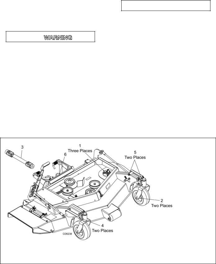
LUBRICATION
1.Do not let excess grease collect on or around parts, particularly when operating in sandy areas.
2.See Figure 7 for lubrication points and frequency of lubrication based on normal operating conditions. Severe or unusual conditions may require more frequent lubrication.
3.Use a lithium grease of #2 consistency with a MOLY (molybdenum disulfide) additive for all locations unless otherwise noted. Be sure to clean fittings thoroughly before attaching grease gun. One good pump of most guns is sufficient when the lubrication schedule is followed.
4.Gearbox requires a minimum of 3 fl. oz. of 90W gear oil. Do not use more than 6 fl. oz.
|
DESCRIPTION |
FREQUENCY |
|
1. |
Mower Blade Spindles |
40 |
Hours |
2. |
Front Gauge Wheel |
8 |
Hours |
3. |
Drive Shaft |
8 |
Hours |
4. |
Caster Pivot |
40 |
Hours |
5. |
Front Lift Linkage |
40 |
Hours |
6. |
Deck Pivot |
8 |
Hours |
7. |
Gearbox |
500 hours |
|
Figure 7. Lubrication Points
16 Service |
MAN0253 (Rev. 3/10/2007) |
|
|
 Loading...