


UNDERMOUNT MOWER
L306 K50
For Use on Kubota Tractors: L2250F L2250DT L2550F L2550DT L2850F L2850DT
with Ag or Turf Tires
32695 |
Rev. 11/17/2006 |
|
Tested. Proven. Unbeatable. |

 OPERATOR'S MANUAL

TO THE DEALER:
Assembly and proper installation of this product is the responsibility of the Woods® dealer. Read manual instructions and safety rules. Make sure all items on the Dealer’s Pre-Delivery and Delivery Check Lists in the Operator’s Manual are completed before releasing equipment to the owner.
The dealer must complete the Product Registration included with the Operator’s Manual. The customer must sign the registration which certifies that all Dealer Check List items have been completed. The dealer is to return the prepaid postage portion to Woods, give one copy to the customer, and retain one copy. Failure to complete and return this card does not diminish customer’s warranty rights.
TO THE OWNER:
Read this manual before operating your Woods equipment. The information presented will prepare you to do a better and safer job. Keep this manual handy for ready reference. Require all operators to read this manual carefully and become acquainted with all adjustment and operating procedures before attempting to operate. Replacement manuals can be obtained from your dealer. To locate your nearest dealer, check the Dealer Locator at www.WoodsEquipment.com, or in the United States and Canada call 1-800-319-6637.
The equipment you have purchased has been carefully engineered and manufactured to provide dependable and satisfactory use. Like all mechanical products, it will require cleaning and upkeep. Lubricate the unit as specified. Observe all safety information in this manual and safety decals on the equipment.
For service, your authorized Woods dealer has trained mechanics, genuine Woods service parts, and the necessary tools and equipment to handle all your needs.
Use only genuine Woods service parts. Substitute parts will void the warranty and may not meet standards required for safe and satisfactory operation. Record the model number and serial number of your equipment in the spaces provided:
Model: _______________________________ |
Date of Purchase: _____________________ |
Serial Number: (see Safety Decal section for location) ____________________________________
Provide this information to your dealer to obtain correct repair parts.
Throughout this manual, the term IMPORTANT is used to indicate that failure to observe can cause damage to equipment. The terms CAUTION, WARNING, and DANGER are used in conjunction with the Safety-Alert Symbol (a triangle with an exclamation mark) to indicate the degree of hazard for items of personal safety.

 DANGER
 WARNING
 CAUTION
IMPORTANT NOTE
This Safety-Alert Symbol indicates a hazard and means ATTENTION! BECOME ALERT! YOUR SAFETY IS INVOLVED!
Indicates an imminently hazardous situation that, if not avoided, will result in death or serious injury.
Indicates a potentially hazardous situation that, if not avoided, could result in death or serious injury, and includes hazards that are exposed when guards are removed.
Indicates a potentially hazardous situation that, if not avoided, may result in minor or moderate injury.
Indicates that failure to observe can cause damage to equipment.
Indicates helpful information.
|
|
|
|
2 Introduction |
Gen’l (Rev. 6/6/2005) |
||
|
|
|
|

TABLE OF CONTENTS
INTRODUCTION . . . . . . . . . . . . . . . . . . . . . . . . . . . . . . . . . . . . . . . . . . . . . . 2 SPECIFICATIONS. . . . . . . . . . . . . . . . . . . . . . . . . . . . . . . . . . . . . . . . . . . . . 4 GENERAL INFORMATION . . . . . . . . . . . . . . . . . . . . . . . . . . . . . . . . . . . . . . 4 SAFETY RULES . . . . . . . . . . . . . . . . . . . . . . . . . . . . . . . . . . . . . . . . . . . . . . 5 SAFETY DECALS . . . . . . . . . . . . . . . . . . . . . . . . . . . . . . . . . . . . . . . . . . . . . 7 OPERATION . . . . . . . . . . . . . . . . . . . . . . . . . . . . . . . . . . . . . . . . . . . . . . . . . 8 OWNER SERVICE . . . . . . . . . . . . . . . . . . . . . . . . . . . . . . . . . . . . . . . . . . . 12 DEALER SERVICE . . . . . . . . . . . . . . . . . . . . . . . . . . . . . . . . . . . . . . . . . . . 14 TROUBLESHOOTING . . . . . . . . . . . . . . . . . . . . . . . . . . . . . . . . . . . . . . . . 16 ASSEMBLY . . . . . . . . . . . . . . . . . . . . . . . . . . . . . . . . . . . . . . . . . . . . . . . . . 18 OPTIONAL EQUIPMENT . . . . . . . . . . . . . . . . . . . . . . . . . . . . . . . . . . . . . . 24 DEALER CHECK LISTS . . . . . . . . . . . . . . . . . . . . . . . . . . . . . . . . . . . . . . . 27 PARTS LISTS . . . . . . . . . . . . . . . . . . . . . . . . . . . . . . . . . . . . . . . . . . . . . . . 28 BOLT TORQUE CHART . . . . . . . . . . . . . . . . . . . . . . . . . . . . . . . . . . . . . . . 35 BOLT SIZE CHART & ABBREVIATIONS . . . . . . . . . . . . . . . . . . . . . . . . . . 36 INDEX . . . . . . . . . . . . . . . . . . . . . . . . . . . . . . . . . . . . . . . . . . . . . . . . . . . . . 38 REPLACEMENT PARTS WARRANTY . . . . . . . . . . . . . . . . . . . . . . . . . . . . 39 PRODUCT WARRANTY . . . . . . . . . . . . . . . . . . . . . . . INSIDE BACK COVER
!LEA EL INSTRUCTIVO!
Si no lee Ingles, pida ayuda a alguien que si lo lea para que le traduzca las medidas de seguridad.
32695 (Rev. 11/17/2006) |
Introduction 3 |
|
|

SPECIFICATIONS
Cutting Width |
72" |
Cutting Height Range |
1-1/2 - 4-1/4 |
Blade Speed (RPM) |
2,180 |
Blade Tip Speed (feet per minute) |
13,840 |
Blade Spindles |
3 |
Number of Blades |
3 |
Caster Wheels |
Optional |
Caster Size |
3-1/4 x 10-1/4 |
PTO Speed |
1,000 Rpm |
Mower Frame Thickness |
7 GA Deck |
GENERAL INFORMATION
The purpose of this manual is to assist you in operating and maintaining your mower. Read it carefully. It furnishes information and instructions that will help you achieve years of dependable performance. These instructions have been compiled from extensive field experience and engineering data. Some information may be general in nature, due to unknown and varying operating conditions. However, through experience and these instructions, you should be able to develop procedures suitable to your particular situation.

■ Some illustrations in this manual show the mower with safety shields removed to provide a better view. The mower should never be operated with any safety shielding removed.
The illustrations and data used in this manual were current at the time of printing. However, due to possible inline production changes, your machine may vary slightly in detail. We reserve the right to redesign and change the machines as may be necessary without notification.
Throughout this manual, references are made to right and left directions. These are determined by standing behind the tractor facing the direction of forward travel. Blade rotation is counter-clockwise as viewed from the top of the mower.
4 Introduction |
32695 (Rev. 11/17/2006) |
|
|

SAFETY RULES
ATTENTION! BECOME ALERT! YOUR SAFETY IS INVOLVED!
Safety is a primary concern in the design and manufacture of our products. Unfortunately, our efforts to provide safe equipment can be wiped out by an operator’s single careless act.
In addition to the design and configuration of equipment, hazard control and accident prevention are dependent upon the awareness, concern, judgement, and proper training of personnel involved in the operation, transport, maintenance, and storage of equipment.
It has been said, “The best safety device is an informed, careful operator.” We ask you to be that kind of operator.
TRAINING
Safety instructions are important! Read all attachment and power unit manuals; follow all safety rules and safety decal information. (Replacement manuals and safety decals are available from your dealer. To locate your nearest dealer, check the Dealer Locator at www.WoodsEquipment.com, or in the United States and Canada call 1-800-319- 6637.) Failure to follow instructions or safety rules can result in serious injury or death.
If you do not understand any part of this manual and need assistance, see your dealer.
Know your controls and how to stop engine and attachment quickly in an emergency.
Operators must be instructed in and be capable of the safe operation of the equipment, its attachments, and all controls. Do not allow anyone to operate this equipment without proper instructions.
Never allow children or untrained persons to operate equipment.
PREPARATION
Check that all hardware is properly installed. Always tighten to torque chart specifications unless instructed otherwise in this manual.
Always wear relatively tight and belted clothing to avoid getting caught in moving parts. Wear sturdy, rough-soled work shoes and protective equipment for eyes, hair, hands, hearing, and head; and respirator or filter mask where appropriate.
Make sure attachment is properly secured, adjusted, and in good operating condition.
Remove accumulated debris from this equipment, power unit, and engine to avoid fire hazard.
Make sure all safety decals are installed. Replace if damaged. (See Safety Decals section for location.)
Make sure shields and guards are properly installed and in good condition. Replace if damaged.
Inspect and clear area of stones, branches, or other hard objects that might be thrown, causing injury or damage.
OPERATION
You may not be able to stop the tractor safely if the clutch or brake pedal mechanisms are improperly adjusted, allowing them to contact mower components.
When the mower lift stops are installed as instructed in this manual, properly adjusted clutch and brake pedal mechanisms will not contact mower components. You should frequently check that the tractor clutch and brake pedal mechanisms are in adjustment.
If the clutch or brake pedal mechanisms can contact mower components, do not put mower into service until properly adjusted.
Do not put mower into service unless discharge chute is installed and in good condition. Replace if damaged.
Keep bystanders away from equipment.
Do not operate or transport equipment while under the influence of alcohol or drugs.
Never direct discharge toward people, animals, or property.
Operate only in daylight or good artificial light.
Keep hands, feet, hair, and clothing away from equipment while engine is running. Stay clear of all moving parts.
Always comply with all state and local lighting and marking requirements.
Never allow riders on power unit or attachment.
Always sit in power unit seat when operating controls or starting engine. Place transmission in neutral, engage brake, and ensure all other controls are disengaged before starting power unit engine.
Look down and to the rear and make sure area is clear before operating in reverse.
Do not operate or transport on steep slopes.
L306 K50 Safety Rules (Rev. 11/3/2006)
Safety 5

SAFETY RULES
ATTENTION! BECOME ALERT! YOUR SAFETY IS INVOLVED!
Do not stop, start, or change directions suddenly on slopes.
Use extreme care and reduce ground speed on slopes and rough terrain.
Watch for hidden hazards on the terrain during operation.
Stop power unit and equipment immediately upon striking an obstruction. Turn off engine, remove key, inspect, and repair any damage before resuming operation.
TRANSPORTATION
Always comply with all state and local lighting and marking requirements.
Never allow riders on power unit or attachment.
Do not operate PTO during transport.
Watch for hidden hazards on the terrain.
Do not operate or transport on steep slopes.
Do not operate or transport equipment while under the influence of alcohol or drugs.
MAINTENANCE
Before dismounting power unit or performing any service or maintenance, follow these steps: disengage power to equipment, lower the 3-point hitch and all raised components to the ground, operate valve levers to release any hydraulic pressure, set parking brake, stop engine, remove key, and unfasten seat belt.
Do not modify or alter or permit anyone else to modify or alter the equipment or any of its components in any way.
Always wear relatively tight and belted clothing to avoid getting caught in moving parts. Wear sturdy, rough-soled work shoes and protective equipment for eyes, hair, hands, hearing, and head; and respirator or filter mask where appropriate.
Never go underneath equipment (lowered to the ground or raised) unless it is properly blocked and secured. Never place any part of the body underneath equipment or between moveable parts even when the engine has been turned off. Hydraulic
system leak down, hydraulic system failures, mechanical failures, or movement of control levers can cause equipment to drop or rotate unexpectedly and cause severe injury or death. Follow Operator's Manual instructions for working underneath and blocking requirements or have work done by a qualified dealer.
Make sure attachment is properly secured, adjusted, and in good operating condition.
Keep all persons away from operator control area while performing adjustments, service, or maintenance.
Make certain all movement of equipment components has stopped before approaching for service.
Frequently check blades. They should be sharp, free of nicks and cracks, and securely fastened.
Do not handle blades with bare hands. Careless or improper handling may result in serious injury.
Your dealer can supply genuine replacement blades. Substitute blades may not meet original equipment specifications and may be dangerous.
Tighten all bolts, nuts, and screws to torque chart specifications. Check that all cotter pins are installed securely to ensure equipment is in a safe condition before putting unit into service.
Make sure all safety decals are installed. Replace if damaged. (See Safety Decals section for location.)
Make sure shields and guards are properly installed and in good condition. Replace if damaged.
Wear gloves when installing belt. Be careful to prevent fingers from being caught between belt and pulley.
STORAGE
Block equipment securely for storage.
Keep children and bystanders away from storage area.
6 Safety
L306 K50 Safety Rules (Rev. 11/3/2006)

SAFETY & INSTRUCTIONAL DECALS
ATTENTION! BECOME ALERT! YOUR SAFETY IS INVOLVED!
Replace Immediately If Damaged!
Serial Number Plate
MODEL NO. |
SERIAL NO. |
Woods Equipment Company
Oregon, Illinois, U.S.A.
|
1 - PN 25505 |
|
|
|
|
2 - PN 53425 |
|
|
|
|
|
DANGER |
|
|
|
|
|
ROTATING BLADES AND |
|
|
|
|
|
THROWN OBJECTS |
|
|
|
|
|
Do not put hands or feet under or into mower when |
|
|
|
|
|
engine is running. |
|
|
|
|
|
Before mowing, clear area of objects that may be |
|
|
|
|
|
thrown by blade. |
|
|
|
|
|
Keep bystanders away. |
|
|
|
|
|
Keep discharge chute and guards in place and in good |
|
|
|
|
|
condition. |
|
|
|
|
|
BLADE CONTACT OR THROWN OBJECTS CAN |
3 - PN 26451 |
|
|
|
|
CAUSE SERIOUS INJURY OR DEATH. |
|
||||
53425-B |
|
||||
BE CAREFUL! |
|
|
|||
|
|
|
|||
Use a clean, damp cloth to clean safety decals. Avoid spraying |
|
||||
|
! |
" |
|||
too close to decals when using a pressure washer; high- |
# |
|
|
||
$ " % &' |
|||||
pressure water can enter through very small scratches or |
|||||
' (& % )& * |
|||||
under edges of decals causing them to peel or come off. |
|||||
" " # |
|
||||
Replacement safety decals can be ordered free from your |
+ % |
||||
" ' |
|||||
Woods dealer. To locate your nearest dealer, check the Dealer |
|||||
+ % |
# |
||||
Locator at www.WoodsEquipment.com, or in the United States |
|
|
|
||
|
|
|
|||
and Canada call 1-800-319-6637. |
|
|
|
|
|
32695 (Rev. 11/17/2006) |
Safety 7 |
|
|
OPERATION
The designed and tested safety of this machine depends on it being operated within the limitations as explained in the manual. Be familiar with and follow all safety rules in this manual, the tractor manual and safety decals on the tractor and mower.
A WARNING
■ Do not exceed PTO speed of 1000 rpm maximum.
The safe operation of this machine is the responsibility of the operator. The operator should be familiar with the mower and tractor and all safety practices before starting operation. Read and follow the safety rules on page 5 through page 7.
The mower is designed for lawn or grass mowing. It is not designed for rough conditions or heavy weed mowing.
It is equipped with suction type blades for best results in lawn mowing. Optional low suction blades are available for use in sandy conditions.
The warranty for this mower appears on the inside back cover of this manual. Record the model and serial numbers of your mower in the spaces provided above the warranty. Provide this information to your dealer to obtain correct repair parts.
Take all possible precautions when leaving tractor unattended: disengage PTO, lower mower, shift into neutral, set parking brake, stop engine and remove key from ignition.
DAILY CHECK LIST
___ Check that mower is properly and securely attached to tractor.
___ During inspection, check that all nuts and bolts are secure and clevis pins are properly cotter pinned.
___ Check condition of blades and security of attachment.
CUTTING HEIGHT ADJUSTMENT WITHOUT CASTERS
Mower cutting height is raised, lowered and maintained using tractor hydraulics and lift chains. Proper lift chain adjustment is essential. The chains must be adjusted so that tractor lift arms are in their highest position before the lift or any part of mower is within 1/4" of contacting tractor or mower lift stops. Improper lift chain adjustment could result in damage to lift mechanism or tractor.
Adjustment is accomplished by lowering lift arms and inserting lift chains into keyhole lift lugs. Raise the mower, checking to ensure it does not contact any part of tractor. Take up links, one or two at a time, until the desired height is obtained.
There is a long and short slot in the rear lift lugs. Level mower by using these slots as needed.
After setting upper lift limit, lower mower to desired cutting height. Set lower stop of mower hydraulic control lever at this point. This will allow you to raise the mower when necessary and return to the pre-set cutting height.
CUTTING HEIGHT ADJUSTMENT WITH CASTERS
The caster arm has five holes for adjustment. Cutting height is adjusted by changing the adjustment bracket hole alignment with the caster arm.
There are two holes on the frame rail to mount the caster arm. Use the rear hole for settings up to 3". Use the front hole for settings above 3".
Whenever adjustments are made to the casters, carefully raise mower to ensure casters do not come in contact with any part of tractor. Should any interference occur, readjust lift chains.
Set lower stop of tractor hydraulic control lever to prevent chains rubbing belt.
IMPORTANT
■Be sure lift chains do not interfere with drive belt.
■Always raise mower off casters when backing up and turning at the same time to prevent casters from locking up on front tires.
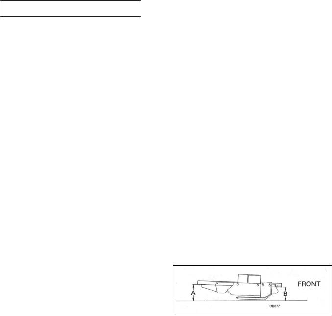
Attitude Adjustment
Figure 1. Attitude Adjustment
Place tractor and mower on a level surface to check and adjust mower attitude. For best mowing results, dimension “A” should not be more than 1/2" higher and never lower than dimension “B” (except when using a leaf mulcher or with some tractor tire configurations, it may be necessary to adjust rear of mower approxi-
8 Operation |
32695 (Rev. 11/17/2006) |
|
|

mately 1/4" lower than front to prevent belt from rubbing on mower.)
Dimension “B” is set by adjusting optional casters or lift chains.
Dimension “A” is set by raising or lowering channel arms in push bars.
IMPORTANT
■ Any adjustment to either dimension “A” or “B” will require checking the other adjustment.
Set desired cutting height with casters or lift chains then adjust for dimension “A”.
Check attitude by placing a straight edge along outside edge of mower as shown in Figure 1. Measure from bottom of straight edge to ground. The measurement at dimension “B” should be level with or approximately 1/2" lower than the rear. The measurement at dimension “A” should never be lower than the one at dimension “B” (except when using a leaf mulcher or with some tractor tire configurations, it may be necessary to adjust rear of mower approximately 1/4" lower than front to prevent belt from rubbing on mower.)
To determine cutting height, it is necessary to subtract the distance the blade is below mower from the measurement at dimension “B”. Subtract 4-7/8" from dimension “B”; the remainder is the cutting height.
Be sure mower is level side to side using these measurements. If it is not, check to be sure casters are set in same hole, and that channel arms and push bars are set in same hole on each side. Minor adjustments can be made by using slots in rear lift bracket for adjustments.
When making cutting height or attitude changes, be sure to check belt alignment. (Refer to Belt Alignment in Assembly section on page 23.)
IMPORTANT
■ Improper belt alignment or tension can cause premature belt failure.
Side Skid Adjustment
With cutting height established, adjust side skids at least 1/2" above ground level. Properly adjusted side skids are designed to carry mower over uneven ground and minimize scalping. Never adjust side skids to be in constant contact with ground.
A WARNING
■ Allow no children or unqualified persons to operate this equipment.
■Do not operate mower in vicinity of other persons.
■Do not allow riders on tractor or mower.
PRE-OPERATION CHECK LIST
___ Check to ensure blades are sharp and secure and cutting edge is positioned in the direction of blade rotation (counter-clockwise as viewed from top of mower).
___ Always operate tractor PTO at 1000 rpm maximum when mowing.
___ Check to make sure all safety shielding is properly installed and is in good condition. Be sure discharge chute or side shield is installed.
___ Check cutting height adjustment.
___ Clear area to be mowed of debris that could be picked up and thrown by mower.
___ Place tractor transmission in neutral and be sure PTO is disengaged before attempting to start tractor engine.
___ Make sure all critical tractor adjustments such as brake and clutch pedal travel, etc., are set to tractor manufacturer’s specifications.
STARTING & STOPPING MOWER
Power for operating the mower is supplied by tractor power take off (PTO). Refer to your tractor manual for PTO operating instruction.
A WARNING
■ Do not exceed PTO speed of 1000 rpm maximum.
A CAUTION
■ Stop mower and tractor immediately upon striking an obstructions. Inspect mower and repair any damage before resuming operation.
Should mower become plugged, causing belt to slip over two seconds, raise mower just enough to clear plug and continue running for at least two minutes, allowing pulleys to cool. Stopping the mower with belt in contact with a very hot pulley will bake and ruin belt. Do not raise mower higher than necessary, to reduce the risk of thrown objects.
Commencing Mowing
When engaging PTO, the engine rpm should always be low. Once engaged and ready to start mowing,
32695 (Rev. 11/17/2006) |
Operation 9 |
|
|

increase PTO speed to 1000 rpm and maintain throughout cutting operation.
During operation mowing vibration tends to loosen hardware. All hardware should be checked regularly to maintain proper torque. It is good practice to check mower before each operation to ensure all hardware is tight.
IMPORTANT
■ Always raise mower off casters when backing and turning at the same time to prevent casters from locking up on front tractor tires.
MOWING TECHNIQUES
Mowing Speed
The condition of the terrain to be cut will determine the smoothness of final results. For best results, mower blades should be kept sharp at all times and the mower as level as possible. When mower blades show excessive wear, they should be replaced.
Proper ground speed for mowing will depend on the height, type and density of grass to be cut. Normally, ground speed will range from two to five mph. Tall, dense grass should be mowed at lower speeds, while thin, medium height grass can be cut at a faster ground speed.
Always operate tractor PTO at 1000 rpm maximum when mowing. This is necessary to maintain proper blade speed to produce a clean cut. Under certain seasonal conditions, front tractor tires may roll some grasses down and prevent them from being cut to the same height as the surrounding area. When this occurs, reduce the tractor ground speed, operating tractor PTO at 1000 rpm. The slower speed will permit grasses to at least partially rebound and be cut.
Under some conditions, the grasses will not rebound enough to be cut evenly, resulting in an uneven appearance. In general, lower mowing heights give a more even cut with less tendency to leave tire tracks.
Mowing Tips
Extremely tall grass should be mowed twice. Cut grass higher on first pass. Cut the second time at desired height at 90° to the first pass.
Remember, sharp blades produce cleaner cuts and use less power.
Before mowing, analyze the area to determine the best mowing procedure. Consider the height, type of grass and the terrain type (hilly, level or rough).
A DANGER
■ Keep away. To avoid serious injury or death from thrown objects or blade contact, never operate mower without discharge chute or side shield installed.
A DANGER
■ Keep hands and feet away from discharge opening.
A WARNING
■Pick up all rocks, twigs and other debris before mowing. Enter new areas carefully. Cut grass higher the first time to allow mower to clear unseen objects. Never assume an area is clear. Always check!
■Clear mowing area of all people when operating mower. Thrown objects could injure bystanders.
Mow with uncut grass to the right. This will distribute the clippings over the cut area. Discharging clippings over uncut grass will cause a buildup and may prevent uniform cutting.
For a professional touch in large open areas, try the mowing pattern in Figure 2. Make two passes counterclockwise to discharge clippings away from bordering objects. Then cut the lawn in half by mowing down the center. Turn clockwise to the right at end of area over grass previously mowed.
Plan your mowing pattern to travel straight forward whenever possible.
It is better to mow grass more often rather than too short. Short grass deteriorates rapidly in hot weather and invites weed growth during growing seasons. Follow local recommendations for the suitable cutting height in your area.
10 Operation |
32695 (Rev. 11/17/2006) |
|
|
Figure 2. Mowing Pattern
BLADES
Mowers are shipped with standard suction blades which are designed for normal mowing conditions.
Optional low suction blades are available for use in sandy areas.
UNEVEN TERRAIN
A WARNING
■ Be careful when operating tractor and mower on uneven ground. In extremely uneven terrain, rear wheel weights should be used to improve traction.
The addition of rear tire weights and liquid ballast in rear tires will increase tractor stability.
Pass diagonally through sharp dips and avoid sharp drops to prevent “hanging up” the tractor and mower. Practice will improve your skills in maneuvering rough terrain.
Avoid sudden starts and stops when traveling up or down hill. Always mow down steep slopes, never up or across the face.
Slow down on sharp turns and slopes to prevent tipping or loss of control.
CLEANING
After Each Use
●Remove large debris such as clumps of dirt, grass, crop residue, etc. from machine.
●Inspect machine and replace worn or damaged parts.
●Replace any safety decals that are missing or not readable.
Periodically or Before Extended Storage
●Clean large debris such as clumps of dirt, grass, crop residue, etc. from machine.
●Remove the remainder using a low-pressure water spray.
1.Be careful when spraying near scratched or torn safety decals or near edges of decals as water spray can peel decal off surface.
2.Be careful when spraying near chipped or scratched paint as water spray can lift paint.
3.If a pressure washer is used, follow the advice of the pressure washer manufacturer.
●Inspect machine and replace worn or damaged parts.
●Sand down scratches and the edges of areas of missing paint and coat with Woods spray paint of matching color (purchase from your Woods dealer).
●Replace any safety decals that are missing or not readable (supplied free by your Woods dealer). See Safety Decals section for location drawing.
32695 (Rev. 11/17/2006) |
Operation 11 |
|
|

OWNER SERVICE
A WARNING
■Lower mower to ground, turn tractor engine off and remove key before performing any maintenance.
■When completing a maintenance or service function, make sure all safety shields are in good condition and properly installed before placing mower in service.
A CAUTION
■ Always use personal protection devices such as eye and ear protectors when performing maintenance functions.
BELT INSTALLATION
See Belt Installation in Assembly section on page 19.
BLADE SERVICING
Blades may be removed from the mower while it is still mounted on the tractor.
A WARNING
■If you suspend mower on tractor hydraulic system, be sure to install safety blocks. The tractor hydraulic system could fail, causing mower to fall and crush anything under it.
■Do not handle mower blades with bare hands. Careless or improper handling may result in serious injury.
Inspect blades before each use to determine that they are mounted tightly and are in good condition. Replace any blade that is bent, excessively nicked, worn or has any other damage. Small nicks can be ground out when sharpening.
BLADE REMOVAL
See Figure 3. Install blade wrench over spindle pulley bolts to prevent spindle from rotating while removing bolt (10) which has left hand threads. Then remove special washer (9), sleeve (8), cup washers (7), shim
washer (6), blade (5), blade stop (4) and clutch disc (3). Shoulder washer (2) will not normally come off machine unless intentionally removed.
BLADE INSTALLATION
See Figure 3. Assemble shoulder washer (2) small end up (if removed). Install remaining parts in reverse order of disassembly. Ensure blade cutting edge is positioned to lead in counter-clockwise rotation, as viewed from top of mower.
Shims should be added to blade installation to leave approximately 1/32" cup in cup washers when blade bolt is torqued to 170 lbs-ft.
Excessive blade slipping can cause the cup washers to burn and lose their clamping force. If this happens, the cup washers must be replaced.
This blade friction clutch disc allows the assembly to slip when hitting a solid object. If slippage occurs during normal mowing, it may be necessary to add an additional shim washer (6).
A WARNING
■Do not substitute any bolt for the special blade bolt. It is self-locking, meeting the non-loosening requirements for this application.
■Your dealer can supply Woods replacement blades. They are made of special steel alloys and subjected to rigid heat-treated and inspections requirements. Substitute blades may not meet these rigid specifications and may be dangerous.
BLADE SHARPENING
IMPORTANT
■ When sharpening blades be sure to balance them. Unbalanced blades will cause excessive vibration which can damage blade spindle bearings. Vibration may also cause structural cracks in mowing housing.
See Figure 4. Follow original sharpening pattern as shown in Figure 4. Do not sharpen blade to a razor edge, but leave a 1/32" to 1/16" blunt edge. Do not sharpen back side of blade.
12 Owner Service |
32695 (Rev. 11/17/2006) |
|
|
 Loading...