


ROTARY CUTTER
DO80-2
MDO80-2
15916 |
Rev. 5/11/2007 |
|
Tested. Proven. Unbeatable. |

 OPERATOR'S MANUAL

TO THE DEALER:
Assembly and proper installation of this product is the responsibility of the Woods® dealer. Read manual instructions and safety rules. Make sure all items on the Dealer’s Pre-Delivery and Delivery Check Lists in the Operator’s Manual are completed before releasing equipment to the owner.
The dealer must complete the Product Registration included with the Operator’s Manual. The customer must sign the registration which certifies that all Dealer Check List items have been completed. The dealer is to return the prepaid postage portion to Woods, give one copy to the customer, and retain one copy. Failure to complete and return this card does not diminish customer’s warranty rights.
TO THE OWNER:
Read this manual before operating your Woods equipment. The information presented will prepare you to do a better and safer job. Keep this manual handy for ready reference. Require all operators to read this manual carefully and become acquainted with all adjustment and operating procedures before attempting to operate. Replacement manuals can be obtained from your dealer. To locate your nearest dealer, check the Dealer Locator at www.WoodsEquipment.com, or in the United States and Canada call 1-800-319-6637.
The equipment you have purchased has been carefully engineered and manufactured to provide dependable and satisfactory use. Like all mechanical products, it will require cleaning and upkeep. Lubricate the unit as specified. Observe all safety information in this manual and safety decals on the equipment.
For service, your authorized Woods dealer has trained mechanics, genuine Woods service parts, and the necessary tools and equipment to handle all your needs.
Use only genuine Woods service parts. Substitute parts will void the warranty and may not meet standards required for safe and satisfactory operation. Record the model number and serial number of your equipment in the spaces provided:
Model: _______________________________ |
Date of Purchase: _____________________ |
Serial Number: (see Safety Decal section for location) ____________________________________
Provide this information to your dealer to obtain correct repair parts.
Throughout this manual, the term IMPORTANT is used to indicate that failure to observe can cause damage to equipment. The terms CAUTION, WARNING, and DANGER are used in conjunction with the Safety-Alert Symbol (a triangle with an exclamation mark) to indicate the degree of hazard for items of personal safety.
|
|
|
|
2 Introduction |
Gen’l (Rev. 2/5/2007) |
||
|
|
|
|
TABLE OF CONTENTS
INTRODUCTION . . . . . . . . . . . . . . . . . . . . . . . . . . . . . . . . . . . . . . . . . . . . . . 2 SPECIFICATIONS . . . . . . . . . . . . . . . . . . . . . . . . . . . . . . . . . . . . . . . . . . . . . 4 GENERAL INFORMATION . . . . . . . . . . . . . . . . . . . . . . . . . . . . . . . . . . . . . . 4 SAFETY VIDEO ORDER FORM . . . . . . . . . . . . . . . . . . . . . . . . . . . . . . . . . . 5 SAFETY RULES . . . . . . . . . . . . . . . . . . . . . . . . . . . . . . . . . . . . . . . . . . . . . . 7 SAFETY DECALS . . . . . . . . . . . . . . . . . . . . . . . . . . . . . . . . . . . . . . . . . . . . 10 OPERATION . . . . . . . . . . . . . . . . . . . . . . . . . . . . . . . . . . . . . . . . . . . . . . . . 13 OWNER SERVICE . . . . . . . . . . . . . . . . . . . . . . . . . . . . . . . . . . . . . . . . . . . 18 DEALER SERVICE . . . . . . . . . . . . . . . . . . . . . . . . . . . . . . . . . . . . . . . . . . . 22 TROUBLESHOOTING . . . . . . . . . . . . . . . . . . . . . . . . . . . . . . . . . . . . . . . . 27 ASSEMBLY . . . . . . . . . . . . . . . . . . . . . . . . . . . . . . . . . . . . . . . . . . . . . . . . . 28 DEALER CHECK LISTS . . . . . . . . . . . . . . . . . . . . . . . . . . . . . . . . . . . . . . . 35 INDEX TO PARTS LIST . . . . . . . . . . . . . . . . . . . . . . . . . . . . . . . . . . . . . . . 37 BOLT TORQUE CHART . . . . . . . . . . . . . . . . . . . . . . . . . . . . . . . . . . . . . . . 58 BOLT SIZE CHART . . . . . . . . . . . . . . . . . . . . . . . . . . . . . . . . . . . . . . . . . . . 59 INDEX . . . . . . . . . . . . . . . . . . . . . . . . . . . . . . . . . . . . . . . . . . . . . . . . . . . . . 60 REPLACEMENT PARTS WARRANTY . . . . . . . . . . . . . . . . . . . . . . . . . . . . 61 PRODUCT WARRANTY . . . . . . . . . . . . . . . . . . . . . . . . . . . . . .BACK COVER
!LEA EL INSTRUCTIVO!
Si no lee Ingles, pida ayuda a alguien que si lo lea para que le traduzca las medidas de seguridad.
15916 (Rev. 3/30/2007) |
Introduction 3 |
|
|

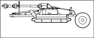
SPECIFICATIONS
|
D080-2 (Towed) |
MD080-2 (Mounted) |
Cutting Width |
80" |
80" |
Cutting Height |
2" - 14" |
2" (Limited by tractor lift) |
Overall Width |
83" |
83" |
Offset to Right of Hitch |
63" |
63" |
Overall Length |
127" |
95" |
Cutter Blade Spindles |
2 |
2 |
Blade Tip Speed (feet per minute) |
14,400 |
14,400 |
V-Belts |
4 |
4 |
Framework Channel |
5/16" |
5/16" |
Spindle Shafts |
1-3/8" |
1-3/8" |
Gearbox |
60 HP |
60 HP |
TRACTOR REQUIREMENTS
|
DO80-2 (Towed) |
MDO80-2 (Mounted) |
Tractor PTO RPM |
540 |
540 |
3-Point Hitch |
N/A |
Category 1 |
|
|
(Category 2 Optional) |
GENERAL INFORMATION
The purpose of this manual is to assist you in operating and maintaining your rotary cutter. Read it carefully. It furnishes information and instructions that will help you achieve years of dependable performance. These instructions have been compiled from extensive field experience and engineering data. Some information may be general in nature due to unknown and varying operating conditions. However, through experience and these instructions, you should be able to develop procedures suitable to your particular situation.
The illustrations and data used in this manual were current at the time of printing, but due to possible inline production changes, your machine may vary slightly in
detail. We reserve the right to redesign and change the machines as may be necessary without notification.
 WARNING
■ Some illustrations in this manual show the equipment with safety shields removed to provide a better view. The equipment should never be operated with any safety shielding removed.
4 Introduction |
15916 (Rev. 3/30/2007) |
|
|

Safety Video Order Form
BE SAFE!
BE ALERT!
BE ALIVE!
BE TRAINED
Before Operating Mowers!
Safety Training
Does Make a Difference.
ASSOCIATION OF
EQUIPMENT
MANUFACTURERS
Free Mower Safety Video
Fill out and return the order form and we will send you a FREE VHS or DVD video outlining Industrial and Agricultural Mower Safety Practices. The 22 minute video, developed in cooperation with AEM (Association of Equipment Manufacturers), reinforces the proper procedures to follow while operating your mowing equipment. The video does not replace the information contained in the Operator’s Manual, so please review this manual thoroughly before operating your new mowing equipment.
Safety Video Order Form (8/2/2005)
Safety 5

Also, available from the Association of Equipment Manufacturers:
A large variety of training materials (ideal for groups) are available for a nominal charge from AEM. Following is a partial list:
●Training Package for Rotary Mowers/Cutters-English
Contains: DVD & VHS (English)
Guidebook for Rotary Mowers/Cutters (English)
AEM Industrial/Agricultural Mower Safety Manual (English) AEM Agricultural Tractor Safety Manual (English)
●Training Package for Rotary Mowers/Cutters-English/Spanish
Contains: DVD & VHS (English/Spanish)
Guidebook for Rotary Mowers/Cutters (English/Spanish)
AEM Industrial/Agricultural Mower Safety Manual (English/Spanish) AEM Agricultural Tractor Safety Manual (English/Spanish)
AEM training packages are available through:
AEM at: www.aem.org or
Hubbard Publishing 800-369-2310 tel 608-846-3398 fax
Free Mower/Cutter Safety Video Order Form
(Select one)
VHS Format - VHS01052 Safety Video
Please send me
DVD Format - DVD01052 Safety Video
Name: ________________________________________ Phone: __________________
Address: _____________________________________
_____________________________________
_____________________________________
Mower/Cutter Model: ______________________ Serial #: ________________________
Send to: ATTENTION: DEALER SERVICES
WOODS EQUIPMENT COMPANY
PO BOX 1000
OREGON IL 61061-1000
6 Safety
Safety Video Order Form (Rev. 2/6/2006)

SAFETY RULES
ATTENTION! BECOME ALERT! YOUR SAFETY IS INVOLVED!
Safety is a primary concern in the design and manufacture of our products. Unfortunately, our efforts to provide safe equipment can be wiped out by an operator’s single careless act.
In addition to the design and configuration of equipment, hazard control and accident prevention are dependent upon the awareness, concern, judgement, and proper training of personnel involved in the operation, transport, maintenance and storage of equipment.
It has been said “The best safety device is an informed, careful operator.” We ask you to be that kind of operator.
Never allow children or untrained persons to operate equipment.
PREPARATION
Check that all hardware is properly installed. Always tighten to torque chart specifications unless instructed otherwise in this manual.
Always wear relatively tight and belted clothing to avoid entanglement in moving parts. Wear sturdy, rough-soled work shoes and protective equipment for eyes, hair, hands, hearing, and head; and respirator or filter mask where appropriate.
Make sure attachment is properly secured, adjusted, and in good operating condition.
TRAINING
Safety instructions are important! Read all attachment and power unit manuals; follow all safety rules and safety decal information. (Replacement manuals and safety decals are available from your dealer. To locate your nearest dealer, check the Dealer Locator at www.WoodsEquipment.com, or in the United States and Canada call 1-800-319- 6637.) Failure to follow instructions or safety rules can result in serious injury or death.
If you do not understand any part of this manual and need assistance, see your dealer.
Know your controls and how to stop engine and attachment quickly in an emergency.
Make sure spring-activated locking pin or collar slides freely and is seated firmly in tractor PTO spline groove.
Make sure driveline guard tether chains are attached to the tractor and equipment as shown in the pamphlet that accompanies the driveline. Replace if damaged or broken. Check that driveline guards rotate freely on driveline before putting equipment into service.
Power unit must be equipped with ROPS or ROPS cab and seat belt. Keep seat belt securely fastened. Falling off power unit can result in death from being run over or crushed. Keep foldable ROPS systems in “locked up” position at all times.
Remove accumulated debris from this equipment, power unit, and engine to avoid fire hazard.
Operators must be instructed in and be capable of the safe operation of the equipment, its attachments, and all controls. Do not allow anyone to operate this equipment without proper instructions.
Keep hands and body away from pressurized lines. Use paper or cardboard, not hands or other body parts to check for leaks. Wear safety goggles. Hydraulic fluid under pressure can easily penetrate skin and will cause serious injury or death.
Make sure that all operating and service personnel know that if hydraulic fluid penetrates skin, it must be surgically removed as soon as possible by a doctor familiar with this form of injury or gangrene, serious injury, or death will result. CONTACT A PHYSICIAN IMMEDIATELY IF FLUID ENTERS SKIN OR EYES. DO NOT DELAY.
Make sure all safety decals are installed. Replace if damaged. (See Safety Decals section for location.)
Make sure shields and guards are properly installed and in good condition. Replace if damaged.
A minimum 20% of tractor and equipment weight must be on the tractor front wheels when attachments are in transport position. Without this weight, tractor could tip over, causing personal injury or death. The weight may be attained with a loader, front wheel weights, ballast in tires or front tractor weights. Weigh the tractor and equipment. Do not estimate.
Inspect and clear area of stones, branches, or other hard objects that might be thrown, causing injury or damage.
(Safety Rules continued on next page)
D80 Safety Rules (Rev. 3/23/2007)
Safety 7

SAFETY RULES
ATTENTION! BECOME ALERT! YOUR SAFETY IS INVOLVED!
(Safety Rules continued from previous page)
Air in hydraulic systems can cause erratic operation and allows loads or equipment components to drop unexpectedly. When connecting equipment or hoses or performing any hydraulic maintenance, purge any air in hydraulic system by operating all hydraulic functions several times. Do this before putti ng into service or allowing anyone to approach the equipment.
OPERATION
Keep bystanders away from equipment.
Operate only in daylight or good artificial light.
Never direct discharge toward people, animals, or property.
Full chain shielding, designed to reduce the possibility of thrown objects, must be installed when operating in populated areas or other areas where thrown objects could injure people or damage property. If this machine is not equipped with full chain shielding, operation must be stopped when anyone comes within 300 feet.
Do not operate or transport equipment while under the influence of alcohol or drugs.
Keep hands, feet, hair, and clothing away from equipment while engine is running. Stay clear of all moving parts.
Always comply with all state and local lighting and marking requirements.
Never allow riders on power unit or attachment.
Power unit must be equipped with ROPS or ROPS cab and seat belt. Keep seat belt securely fastened. Falling off power unit can result in death from being run over or crushed. Keep foldable ROPS systems in “locked up” position at all times.
Always sit in power unit seat when operating controls or starting engine. Securely fasten seat belt, place transmission in neutral, engage brake, and ensure all other controls are disengaged before starting power unit engine.
Operate tractor PTO at 540 RPM. Do not exceed.
Look down and to the rear and make sure area is clear before operating in reverse.
Do not operate or transport on steep slopes.
Do not stop, start, or change directions suddenly on slopes.
Use extreme care and reduce ground speed on slopes and rough terrain.
Watch for hidden hazards on the terrain during operation.
Stop power unit and equipment immediately upon striking an obstruction. Turn off engine, remove key, inspect, and repair any damage before resuming operation.
TRANSPORTATION
Power unit must be equipped with ROPS or ROPS cab and seat belt. Keep seat belt securely fastened. Falling off power unit can result in death from being run over or crushed. Keep foldable ROPS system in “locked up” position at all times.
The maximum transport speed for towed and semi-mounted machines is 20 mph (32 km/h). Regardless of the maximum speed capability of the towing tractor, do not exceed the implement’s maximum transport speed. Doing so could result in:
•Loss of control of the implement and tractor
•Reduced or no ability to stop during braking
•Implement tire failure
•Damage to the implement or its components.
Always comply with all state and local lighting and marking requirements.
Never allow riders on power unit or attachment.
Do not operate PTO during transport.
Do not operate or transport on steep slopes.
Do not operate or transport equipment while under the influence of alcohol or drugs.
Never tow this implement with a motor vehicle.
MAINTENANCE
Before performing any service or maintenance, lower equipment to ground or block securely, turn off engine, remove key, and disconnect driveline from tractor PTO.
Do not modify or alter or permit anyone else to modify or alter the equipment or any of its components in any way.
Always wear relatively tight and belted clothing to avoid entanglement in moving parts. Wear sturdy, rough-soled work shoes and protective equipment for eyes, hair, hands, hearing, and head; and respirator or filter mask where appropriate.
Never go underneath equipment (lowered to the ground or raised) unless it is properly blocked and secured. Never place any part of the body underneath equipment or between moveable parts even
8 Safety
D80 Safety Rules (Rev. 3/23/2007)

SAFETY RULES
ATTENTION! BECOME ALERT! YOUR SAFETY IS INVOLVED!
when the engine has been turned off. Hydraulic system leak down, hydraulic system failures, mechanical failures, or movement of control levers can cause equipment to drop or rotate unexpectedly and cause severe injury or death. Follow Operator's Manual instructions for working underneath and blocking requirements or have work done by a qualified dealer.
Make sure attachment is properly secured, adjusted, and in good operating condition.
Keep all persons away from operator control area while performing adjustments, service, or maintenance.
Make certain all movement of equipment components has stopped before approaching for service.
Frequently check blades. They should be sharp, free of nicks and cracks, and securely fastened.
Your dealer can supply genuine replacement blades. Substitute blades may not meet original equipment specifications and may be dangerous.
Make sure shields and guards are properly installed and in good condition. Replace if damaged.
Tighten all bolts, nuts and screws to torque chart specifications. Check that all cotter pins are installed securely to ensure equipment is in a safe condition before putting unit into service.
Make sure all safety decals are installed. Replace if damaged. (See Safety Decals section for location.)
Do not handle blades with bare hands. Careless or improper handling may result in serious injury.
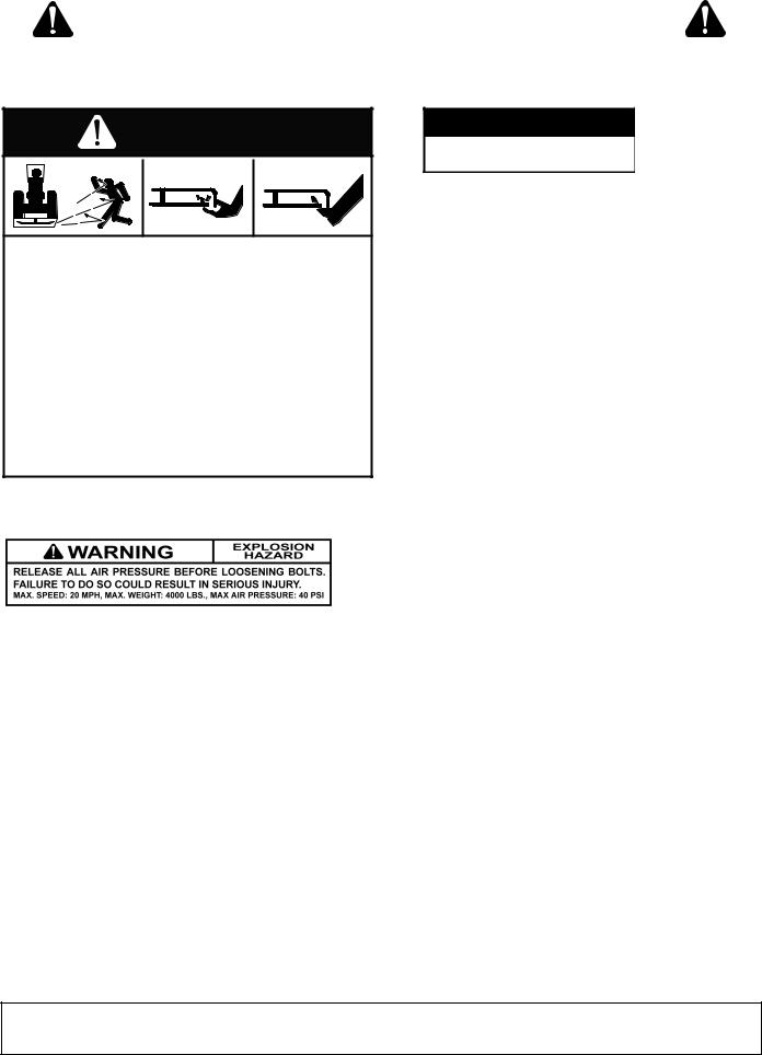
Explosive separation of tire and rim parts can cause serious injury or death. Release all air pressure before loosening bolts.
STORAGE
Raise cutter and block securely. Block wheels and raise tongue with jack. Disconnect hydraulic lines to optional cylinder. Disconnect driveline and secure up off the ground.
Keep children and bystanders away from storage area.
Store on level, solid ground.
Follow manual instructions for storage.
(Rev. 5/11/2007)
D80 Safety Rules (Rev. 3/23/2007)
Safety 9

SAFETY & INSTRUCTIONAL DECALS
ATTENTION! BECOME ALERT! YOUR SAFETY IS INVOLVED!
Replace Immediately If Damaged!
11 |
|
|
9 |
PULL-TYPE |
|
|
PULL-TYPE |
ONLY |
7 |
|
|
7 |
|
|
ONLY |
11 |
|
12 |
|
|
|
|
|
|
12 |
|
PULL-TYPE |
|
|
|
|
|
|
8 |
ONLY |
|
|
12 |
|
10 |
5 |
|
|
|
|
|
|
|
|
|
9 |
6 |
13 |
|
|
|
|
|
12 |
|
|
|
6 |
|
1 |
3 |
|
11 |
|
|
FRAME FOR |
|
4 |
|
MOUNTED & |
|
7 |
|
PULL-TYPE |
|
|
|
|
MOUNTED |
2 |
CD3841B |
|
DRIVE |
|
|
|
1 - SERIAL NUMBER PLATE
MODEL NO. |
SERIAL NO. |
Woods Equipment Company
Oregon, Illinois, U.S.A.
4 - 18866
 WARNING
540RPM
! " #$
18866-D
2 - 18865
 WARNING
FALLING OFF CAN RESULT IN BEING RUN OVER.
Tractor must be equipped with ROPS (or ROPS CAB) and seat belt. Keep foldable ROPS systems in “locked up” position at all times.
Buckle Up! Keep seat belt securely fastened.
Allow no riders.
RAISED EQUIPMENT CAN DROP AND CRUSH.
Before working underneath, follow all instructions and safety rules in operator’s manual and securely block up all corners of equipment with jack stands.
Securely blocking prevents equipment dropping from hydraulic leakdown, hydraulic system failures or mechanical component failures.
FALLING OFF OR FAILING TO BLOCK SECURELY CAN RESULT IN SERIOUS INJURY OR DEATH.
10 SAFETY |
15916 (Rev. 3/30/2007) |
|
SAFETY & INSTRUCTIONAL DECALS
ATTENTION! BECOME ALERT! YOUR SAFETY IS INVOLVED!
Replace Immediately If Damaged!
3 - 18877
 WARNING
TO AVOID SERIOUS INJURY OR DEATH:
Read Operator's Manual (available from dealer) and follow all safety precautions.
Keep all shields in place and in good condition.
Operate mower from tractor seat only.
Lower mower, stop engine and remove key before dismounting tractor.
Allow no children or untrained persons to operate equipment.
Do not transport towed or semi-mounted units over 20 mph.
FAILURE TO OPERATE SAFELY
CAN RESULT IN
INJURY OR DEATH.
18877-C
5 - 18867
 DANGER
SHIELD MISSING
DO NOT OPERATE
PUT SHIELD ON
18867--B
8 - 15951
1133347


33347E


7 - 18864
DANGER
ROTATING DRIVELINE
CONTACT CAN CAUSE DEATH
KEEP AWAY!
DO NOT OPERATE WITHOUT -
All driveline guards, tractor and equipment shields in place
Drivelines securely attached at both ends
Driveline guards that turn freely on
driveline |
18864-C |
|
6 - 15502
WARNING
ROTATING COMPONENTS
Do not operate without cover in place.
Look and listen for rotation. Do not open cover until all components have stopped.
CONTACT WITH ROTATING PARTS
CAN CAUSE SERIOUS INJURY.
15502--B
 WARNING
A RAISED CUTTER CAN DROP AND CRUSH
Cutter must have crank with pin installed to prevent crank detachment.
Before working underneath, rotate crank to highest position and block up cutter.
Blocking up prevents cutter dropping from hydraulic leak down, hydraulic system failures, or mechanical component failures.
FAILURE TO FOLLOW INSTRUCTIONS CAN RESULT IN SERIOUS INJURY OR DEATH.
 28-1/4—
CRANK |
PIN |
CYLINDER AND CRANK
REQUIREMENTS
15951-B
9 - 19924
WARNING
Check for leaks with cardboard; never use hand.
Before loosening fittings: lower load, release pressure, and be sure oil is cool.
Consult physician immediately if skin penetration occurs.
12 - RED REAR REFLECTOR 4.5" PN 20106
15916 (Rev. 3/30/2007) |
SAFETY 11 |
|
|
SAFETY & INSTRUCTIONAL DECALS
ATTENTION! BECOME ALERT! YOUR SAFETY IS INVOLVED!
Replace Immediately If Damaged!
10 - 15503
DANGER
ROTATING BLADES AND
THROWN OBJECTS
Do not put hands or feet under or into mower when engine is running.
Before mowing, clear area of objects that may be thrown by blade.
Keep bystanders away.
Keep guards in place and in good condition.
BLADE CONTACT OR THROWN OBJECTS CAN CAUSE SERIOUS INJURY OR DEATH.
15503-C
13 - 18869
 DANGER
SHIELD MISSING |
-B |
|
18869 |
||
DO NOT OPERATE - PUT SHIELD ON |
||
|
BE CAREFUL!
Use a clean, damp cloth to clean safety decals.
Avoid spraying too close to decals when using a pressure washer; high-pressure water can enter through very small scratches or under edges of decals causing them to peel or come off.
Replacement safety decals can be ordered free from your Woods dealer. To locate your nearest dealer, check the Dealer Locator at www.WoodsEquipment.com, or in the United States and
Canada call 1-800-319-6637.
PN 1006348
12 SAFETY
(Rev. 5/11/2007) 15916 (Rev. 3/30/2007)

OPERATION
The designed and tested safety of this machine depends on it being operated within the limitations as explained in this manual. Be familiar with and follow all safety rules in the manual, on the cutter and on the tractor.
The safe operation of this cutter is the responsibility of the operator, who must be properly trained. The operator should be familiar with the equipment and all safety practices before starting operation. Read the Safety Rules on page 7 through page 12.
Information specific to attaching or operating the mounted or towed unit will be identified in the text. Information applicable to either unit will not be segregated.
This cutter is designed for shredding heavy brush, such as prunings in orchards, groves and vineyards. Other applications include topping onion sets and potatoes before harvesting. It may also be used to shred green manure crops, straw and stubble, asparagus residue etc. prior to plowing. Recommended tractor ground speed for most mowing conditions is from 1 to 5 mph. Always operate tractor PTO at 540 rpm.
 DANGER
Full chain shielding, designed to reduce the possibility of thrown objects, must be installed when operating in populated areas or other areas where thrown objects could injure people or damage property. If this machine is not equipped with full chain shielding, operation must be stopped when anyone comes within 300 feet.
 WARNING
Never allow children or untrained persons to operate equipment.
Keep bystanders away from equipment.
Before performing any service or maintenance, lower equipment to ground or block securely, turn off engine, remove key, and disconnect driveline from tractor PTO.
On pull-type units, a pin is installed to prevent the height adjustment crank from detaching. Do not operate or service unit unless pin is installed.
Keep all persons away from operator control area while performing adjustments, service, or maintenance.
 CAUTION
Always wear relatively tight and belted clothing to avoid getting caught in moving parts. Wear sturdy, rough-soled work shoes and protective equipment for eyes, hair, hands, hearing, and head; and respirator or filter mask where appropriate.
Make sure spring-activated locking pin or collar slides freely and is seated firmly in tractor PTO spline groove.
Stop power unit and equipment immediately upon striking an obstruction. Turn off engine, remove key, inspect, and repair any damage before resuming operation.
TRACTOR STABILITY
 WARNING
A minimum 20% of tractor and equipment weight must be on the tractor front wheels when attachments are in transport position. Without this weight, tractor could tip over, causing personal injury or death. The weight may be attained with a loader, front wheel weights, ballast in tires or front tractor weights. Weigh the tractor and equipment. Do not estimate.
ATTACHING CUTTER TO TRACTOR (3-POINT MODELS)
 WARNING
Make sure spring-activated locking pin or collar slides freely and is seated firmly in tractor PTO spline groove.
MD80 Mounting
Standard Category 1 mounting pins are used when attaching cutter to tractor. Also available for mounting are optional Category 2 pins and a bushing kit.
Check to be sure mounting pins are properly torqued - Category 1: 300 lbs-ft.; Category 2: 450 lbs-ft.
Install tractor lower lift arms over the cutter mounting pins. Attach tractor top link in top hole of cutter A- frame. Use bushing over top link clevis pin when mounting on a Category 2 tractor.
15916 (Rev. 3/30/2007) |
Operation 13 |
|
|
Driveline Attachment
Attach the cutter to the tractor 3-point hitch (or quick hitch if available). Do not attach driveline. Raise and lower cutter to determine maximum and minimum distance between the tractor PTO shaft and the gearbox input shaft. If the distance is too large, the driveline will be too short for proper engagement. If distance is too small, the driveline may bottom out in operation and damage the cutter or tractor.
Driveline length must be sufficient to provide at least 1/3 driveline length of engagement during operation. There must be at least 4 inches of engagement at the cutters lowest possible point of operation. The driveline must not bottom out when raised to the maximum height possible.
If driveline is too short please call your Woods dealer for a longer driveline.
If driveline is too long please follow the instructions for shortening the driveline.
Shorten Driveline
1.Move cutter up and down to get the shortest possible distance between tractor PTO shaft and gearbox input shaft.
2.Separate driveline into two halves and connect them to the tractor PTO and gearbox.
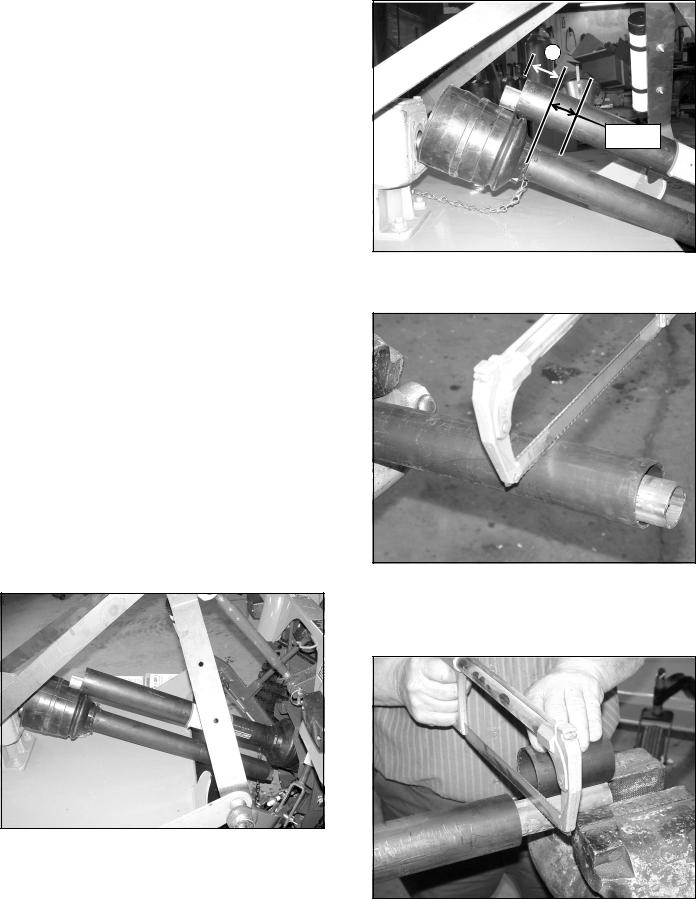
3.Place driveline halves parallel to one another to determine how much to shorten the driveline.
Figure 1. Drive Halves Placed Parallel
4.Measure from end of the upper shield to the base of the bell on the lower shield (A). Add 1-9/16" to dimension (A). See Figure 2.
A
1-9/16"
Figure 2. Determine Shield Length
5. Cut the shield to the overall dimension.
Figure 3. Cut Shield
6.Place the cutoff portion of the shield against the end of the shaft and use as a guide. Mark and cut the shaft.
Figure 4. Cut Shaft to Length
14 Operation |
15916 (Rev. 3/30/2007) |
|
|
7.Repeat step 6 for the other half of the drive.
8.File and clean cut ends of both drive halves.
Do not use tractor if proper driveline engagement cannot be obtained through these methods.
Connect driveline to tractor PTO shaft, making sure the spring-activated locking collar slides freely and locks driveline to PTO shaft.
NOTICE
■ If attaching with quick hitch the distance between the tractor PTO and gearbox input shaft will increase. Please follow the steps as you would for a 3-point hitch to insure proper engagement.
Cutting Height Adjustment for MD80 Mounted Cutter (Figure 5)
Place tractor and cutter on a level surface.
The adjustments given here are to provide you with a starting point. Adjustments are approximate and may vary due to slight differences in blade shimming and machine wear. You may desire to fine tune them for your situation.
 WARNING
Keep all persons away from operator control area while performing adjustments, service, or maintenance.
■ Avoid very low cutting heights. Striking the ground with blades produces one of the most damaging shock loads a cutter can encounter. Allowing blades to contact ground repeatedly, will cause damage to cutter and drive.
Cutting height may be controlled by several methods. Without the optional check chains and tailwheel it is controlled with the tractor 3-point lift and top link adjustment.
Measure from front edge of cutter frame (on each side) to ground to be sure cutter is level. Use adjustment on 3-point arms, if necessary, for fine adjustment side to side.
2 |
3 |
4 |
1 |
M3838 |
1. |
Check chains |
3. |
Lift channel |
2. |
Top link |
4. |
Tailwheel adj. |
Figure 5. Cutting Height Adjustment - MD80
(Mounted Model)
When using optional check chains, install them in keyhole brackets. Count the links between the cutter and brackets to be sure you have the same number of links on each side. You may twist check chain for fine adjustment side to side.
Cutting Height Adjustment Without Tailwheel or Check Chains
The blade is approximately 9-1/4" below the top of the cutter deck.
Select a cutting height, EXAMPLE 3".
Use tractor 3-point lift to set front blade 3" above level surface (measure 12-1/4" from top of deck to ground). At the rear, measure from top of deck to ground; adjust top link until this distance is from 12-3/4" to 13". Adjust lower stop of the tractor 3-point lift control. When adjustment is set, this will enable you to return to the preset cutting height.
Maintain distance from blade tip to level surface from 1/2" to 3/4" higher at rear for best cutting results and lowest power consumption.
When using cutter for shredding, it is better to set blade tip lower at the rear. How much lower depends on the material to be shredded. You will need to experiment to determine the best setting for your situation.
Cutting Height Adjustment With Tailwheel or Check Chains
The blade is approximately 9-1/4" below the top of the cutter deck.
Select a cutting height, EXAMPLE 3".
Use check chains and tractor 3-point lift and raise top front of cutter deck 12-1/4" above the level surface. At the rear, measure from top of deck to ground; adjust tailwheel until this distance is from 12-3/4" to 13".
Shorten the check chains to raise front of cutter. Move tailwheel adjustment to the rear to raise rear of cutter.
15916 (Rev. 3/30/2007) |
Operation 15 |
|
|
ATTACHING CUTTER TO TRACTOR (PULL-TYPE MODELS)
The cutter is shipped with a 1-3/8" PTO spline. The horizontal distance between the end of the tractor PTO shaft and the drawbar hitch point should be 14". This distance must not vary more than plus or minus one inch (±1") or the drive may be damaged when turning. Adjust tractor drawbar to obtain the desired drawbar to hitch point distance. On some tractors, a drawbar kit must be used to obtain the required dimension. Check with your tractor dealer if you encounter problems.
Raise cutter tongue to tractor drawbar height with jack provided and attach with a 3/4" or larger high-strength drawbar pin. Retain pin to keep it in place.
Connect cutter driveline to tractor PTO shaft, making sure the spring-activated locking pin slides freely and is seated firmly in tractor PTO spline groove.
Adjust H-frame bearing height to ensure front driveline is parallel to ground.
Remove parking jack from tongue. Attach to frame rail storage with top forward. Always attach jack to tongue to hold it up when disconnecting it from tractor.
Adjust drive shaft carrier bearing (2), Figure 6, vertically in H-frame until driveline is as straight as possible between tractor PTO and cutter gearbox.
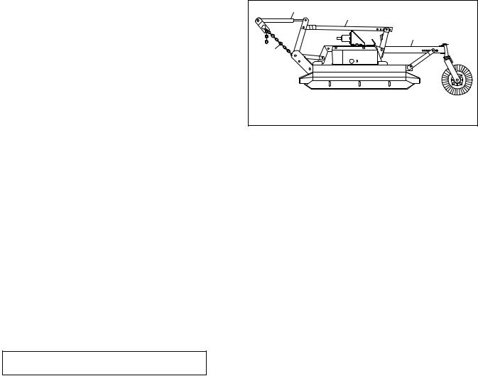
Cutting Height Adjustment for D80 Pull-Type Cutter (Figure 6)
Place tractor and cutter on a level surface.
Cutting height is raised and lowered with height adjustment crank (3) or optional hydraulic cylinder. Front to rear attitude is set with the compression link (1). The blade is approximately 9-1/4" below cutter deck. Select a cutting height, EXAMPLE 3".
Raise front end of deck with a jack to take the compression member (1) out of compression and remove the bolt connecting it to the tongue.
Raise front end of deck until both sides are 12-1/4" above the ground and block underneath to maintain this distance.
Raise rear end of deck until it is from 13-3/4" to 14" above the ground.
Connect compression member (1) to tongue. It may be necessary to raise or lower rear of deck to align hole.
Remove the blocks from under the deck and position each side skid 1/2" above the ground.
This complete procedure must be followed to properly set a new cutting height. Raising rear of deck with crank without changing the compression link position will result in an incorrect front-to-rear attitude setting.
1. Compression member |
M3866 |
|
|
||
2. |
Carrier bearing |
|
3. |
Adjustment crank |
|
Figure 6. Cutting Height Adjustment - D80
(Pull-Type Model)
PRE-OPERATION CHECK LIST
(Owner’s Responsibility)
___ Check that cutter is properly and securely attached to tractor.
___ Make sure driveline spring-activated locking pin slides freely and is seated firmly in tractor PTO spline groove.
___ On pull-type cutter, make sure the pin to prevent crank detachment is installed.
___ Set tractor PTO at 540 rpm.
___ Make sure gearbox is full to fill plug with SAE 90W gear lube.
___ Lubricate all grease fitting locations.
___ Check that all hardware is properly installed and secured.
___ Check to ensure blades are sharp and secure and cutting edge is positioned to lead in a counter-clockwise rotation.
___ Check that all shields and guards are properly installed and in good condition.
___ Check cutting height and attitude adjustment.
___ Place tractor PTO and transmission in neutral before attempting to start engine.
___ Inspect area to be cut and remove stones, branches or other hard objects that might be thrown, causing injury or damage.
___ Inspect chain shielding and replace any damaged or missing links.
STARTING AND STOPPING CUTTER
Cutter operating power is supplied from tractor PTO. Refer to your tractor manual for PTO engagement and disengagement instructions. Always operate PTO at 540 rpm. Know how to stop tractor and cutter quickly in case of an emergency.
When engaging PTO, the engine rpm should always be low. Once engaged and ready to start cutting, raise PTO speed to 540 rpm and maintain throughout cutting operation.
16 Operation |
15916 (Rev. 3/30/2007) |
|
|

OPERATING TECHNIQUE
Proper ground speed will depend upon the height, type and density of material to be cut.
Normally, ground speed will range from 2 to 5 mph. Tall dense material should be cut at a low speed, while thin medium-height material can be cut at a higher ground speed. Always operate PTO at 540 rpm; this is necessary to maintain proper blade speed and produce a clean cut.
Under certain conditions, tractor tires may roll some material down and prevent it from being cut at the same height as the surrounding area. When this occurs, reduce tractor ground speed but maintain 540 rpm PTO speed. The lower speed will permit material to at least partially rebound.
Under some conditions, material will not rebound enough to be cut evenly, resulting in an uneven appearance. In general, lower cutting heights give a more even cut with less tendency to leave tire tracks.
The cutter is equipped with general purpose suction blades as standard equipment. These blades are intended for most conditions. Optional flat blades for light brush cutting and optional high fin blades for stalk shredding are available from your dealer.
Tips
Extremely tall material should be cut twice. Cut material higher the first pass. Then cut at desired height, at 90° to first pass. Remember, sharp blades produce cleaner cuts and require less power.
Analyze area to be cut to determine best procedure. Consider height and type of material and terrain type: hilly, level or rough. Plan your pattern to travel straight forward whenever possible.
 WARNING
Inspect and clear area of stones, branches, or other hard objects that might be thrown, causing injury or damage.
Uneven Terrain
 WARNING
Do not operate or transport on steep slopes.
Do not stop, start, or change directions suddenly on slopes.
Use extreme care and reduce ground speed on slopes and rough terrain.
Watch for hidden hazards on the terrain during operation.
Pass diagonally through sharp dips and avoid sharp drops to prevent hanging up tractor and cutter.
Practice will improve your skills in maneuvering rough terrain.
CLEANING
After Each Use
●Remove large debris such as clumps of dirt, grass, crop residue, etc. from machine.
●Inspect machine and replace worn or damaged parts.
●Replace any safety decals that are missing or not readable.
Periodically or Before Extended Storage
●Clean large debris such as clumps of dirt, grass, crop residue, etc. from machine.
●Remove the remainder using a low-pressure water spray.
1.Be careful when spraying near scratched or torn safety decals or near edges of decals as water spray can peel decal off surface.
2.Be careful when spraying near chipped or scratched paint as water spray can lift paint.
3.If a pressure washer is used, follow the advice of the pressure washer manufacturer.
●Inspect machine and replace worn or damaged parts.
●Sand down scratches and the edges of areas of missing paint and coat with Woods spray paint of matching color (purchase from your Woods dealer).
●Replace any safety decals that are missing or not readable (supplied free by your Woods dealer). See Safety Decals section for location drawing.
STORAGE
Follow these steps when storing your cutter:
1.Store on level, solid ground.
2.Disconnect driveline and secure up off the ground.
3.On pull-type model, attach parking jack and raise tongue weight off tractor drawbar.
4.Securely block all four corners of deck with jack stands.
5.Remove hydraulic hoses after tractor is turned off and all system pressure is released by operating valve levers several times.
6.Remove retainer pin and high strength drawbar pin.
7.Keep children and bystanders away from storage area.
15916 (Rev. 3/30/2007) |
Operation 17 |
|
|

OWNERS SERVICE
 WARNING
On pull-type units, a pin is installed to prevent the height adjustment crank from detaching. Do not operate or service unit unless pin is installed.
Before performing any service or maintenance, lower equipment to ground or block securely, turn off engine, remove key, and disconnect driveline from tractor PTO.
Keep all persons away from operator control area while performing adjustments, service, or maintenance.
 CAUTION
Always wear relatively tight and belted clothing to avoid getting caught in moving parts. Wear sturdy, rough-soled work shoes and protective equipment for eyes, hair, hands, hearing, and head; and respirator or filter mask where appropriate.
The information in this section is written for operators who possess basic mechanical skills. Should you need help, your dealer has trained service technicians available. For your protection, read and follow all safety information in this manual.
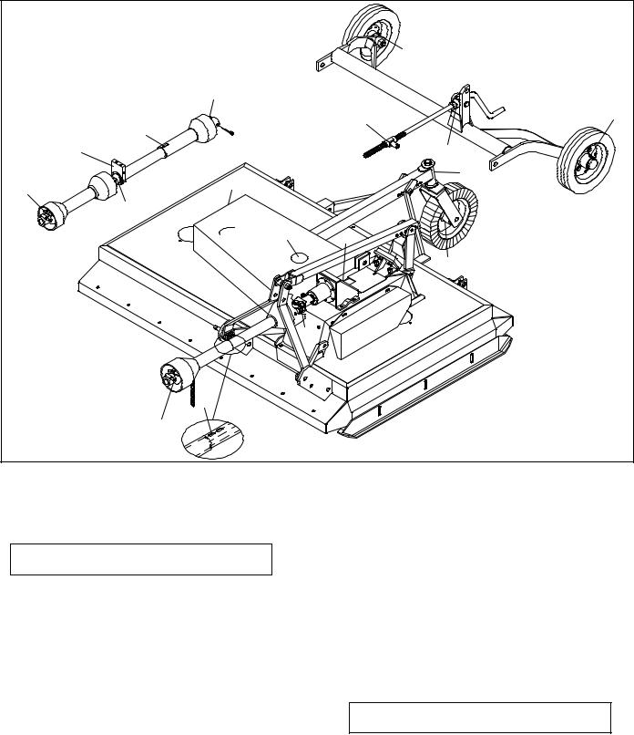
LUBRICATION INFORMATION (FIGURE 7)
The accompanying chart gives the frequency of lubrication in operating hours, based on normal conditions. Severe or unusual conditions may require more frequent lubrication.
Do not let excess grease collect on or around parts, particularly when operating in sandy areas.
Use an SAE 90W gear lube in gearbox.
Use a lithium grease of No. 2 consistency with a MOLY (molybdenum disulfide) additive for all locations. Be
sure to clean fittings thoroughly before attaching grease gun. When applied according to the lubrication chart, one good pump of most guns is sufficient. Do not overgrease.
Daily lubrication of the PTO slip joint is necessary. Failure to maintain proper lubrication can result in damage to U-joints, gearbox, tractor PTO and/or cutter driveline.
Ref |
|
|
No Description |
Frequency |
|
1 |
Tailwheel Hub (Towed Model) |
10 hrs |
2 |
Tailwheel Pivot Arm |
8 hrs |
3 |
Tailwheel (Mounted Model) |
8 hrs |
4Blade Spindle - Access through hole in end of belt shield (right);
|
Remove left belt shield (left) |
10 hrs |
5 |
Belt Idler - Access through hole |
|
|
in top of belt shield (right); |
|
|
Remove left belt shield (left) |
50 hrs |
6 |
Gearbox: Fill with EP90 gear |
|
|
lube |
Check Daily |
7 |
Rear U-Joint |
8 hrs |
8Slip Joint (Mounted Model) - Apply grease to all four sides
|
of shaft |
8 hrs |
9 |
Front U-Joint |
8 hrs |
10 |
Center U-Joint (Towed Model) |
10 hrs |
11 |
Driveline Carrier Bearing |
|
|
(Towed Model) |
10 hrs |
12 |
Slip Joint (Towed Model) - |
|
|
Apply grease to all four sides |
|
|
of shaft |
10 hrs |
13 |
Height Adjustment Pivot Block |
Occasionally |
14 |
Height Adjustment Crank |
Occasionally |
18 Owner Service |
15916 (Rev. 3/30/2007) |
|
|
|
|
|
1 |
|
|
|
PULL-TYPE |
|
7 |
|
|
PULL-TYPE |
|
13 |
1 |
12 |
|
|
|
|
|
|
|
11 |
|
|
14 |
|
|
|
|
|
4 |
|
2 |
9 |
|
|
|
|
|
|
|
|
10 |
|
|
|
5 |
6 |
|
|
|
|
3 |
|
|
7 |
|
|
8 |
|
|
|
9 |
|
CD3847 |
|
|
|
|
|
MOUNTED |
|
|
Figure 7. Lubrication Points
BLADE SERVICING (FIGURE 8)
 WARNING
On pull-type units, a pin is installed to prevent the height adjustment crank from detaching. Do not operate or service unit unless pin is installed.
Blocking the cutter before working underneath provides additional safety. If a mechanical or hydraulic failure occurs, the blocks will support the cutter and prevent anyone under it from being crushed.
Inspect blades, each time before operating cutter, for condition and proper installation. Check to be sure blades are snug but still swivel on blade pin (see Blade Installation, page 20). Replace any blade that is bent, excessively nicked, worn or has any other damage. Small nicks can be ground out when sharpening.
Blade Removal (Figure 8)
Rotate crossbar until blade pin assembly is directly below access hole in rear of cutter frame. Remove bolt
(1) and blade pin lock clip (2). Slide keyhole plate (3) out of blade pin groove and remove. Remove spacers and drive pin out of crossbar.
NOTICE
■ If blade pin is seized in crossbar and extreme force will be required to remove it, support crossbar from below to prevent damage to spindle.
 CAUTION
Your dealer can supply genuine replacement blades. Substitute blades may not meet original equipment specifications and may be dangerous.
15916 (Rev. 3/30/2007) |
Owner Service 19 |
|
|
 Loading...