


Wolf ML-126756, ML-126757, ML-126755, ML-126760, ML-126759 User Manual
...
OWNER’S MANUAL
INSTALLATION & OPERATION
WKE SERIES
ELECTRIC
CONVECTION OVENS
MODELS |
|
WKE |
ML-126755 |
WKED |
ML-126756 |
WKEC |
ML-126757 |
WKEX |
ML-126758 |
WKEDX |
ML-126759 |
WKECX |
ML-126760 |
THE WOLF RANGE COMPANY LLC
19600 S. Alameda St., Compton, California 90221-6291
P. O. Box 7050, Compton, California 90240-7050 ® (310) 637-3737 • FAX (310) 637-7931 • (800) 366-WOLF
FORM 31162 (Apr. 2000)

TABLE OF CONTENTS
GENERAL . . . . . . . . . . . . . . . . . . . . . . . . . . . . . . . . . . . . . . . . . . . . . . . . . . . . . . . . . . . . . . . . . . 3
INSTALLATION . . . . . . . . . . . . . . . . . . . . . . . . . . . . . . . . . . . . . . . . . . . . . . . . . . . . . . . . . . . . . . 3 Unpacking . . . . . . . . . . . . . . . . . . . . . . . . . . . . . . . . . . . . . . . . . . . . . . . . . . . . . . . . . . . . . . 3 Location . . . . . . . . . . . . . . . . . . . . . . . . . . . . . . . . . . . . . . . . . . . . . . . . . . . . . . . . . . . . . . . . 4 Installation Codes and Standards . . . . . . . . . . . . . . . . . . . . . . . . . . . . . . . . . . . . . . . . . . . 4 Installing Basic Oven . . . . . . . . . . . . . . . . . . . . . . . . . . . . . . . . . . . . . . . . . . . . . . . . . . . . . 4 Assembling the Legs to the Single Oven . . . . . . . . . . . . . . . . . . . . . . . . . . . . . . . . . . . . . 4 Leveling . . . . . . . . . . . . . . . . . . . . . . . . . . . . . . . . . . . . . . . . . . . . . . . . . . . . . . . . . . . . . . . . 4 Casters . . . . . . . . . . . . . . . . . . . . . . . . . . . . . . . . . . . . . . . . . . . . . . . . . . . . . . . . . . . . . . . . 4 Assembling the Stand to the Oven . . . . . . . . . . . . . . . . . . . . . . . . . . . . . . . . . . . . . . . . . . 4 Electrical Connections . . . . . . . . . . . . . . . . . . . . . . . . . . . . . . . . . . . . . . . . . . . . . . . . . . . . 5 Assembling Stacked Ovens . . . . . . . . . . . . . . . . . . . . . . . . . . . . . . . . . . . . . . . . . . . . . . . . 5 Electrical Connections (Stacked Ovens) . . . . . . . . . . . . . . . . . . . . . . . . . . . . . . . . . . . . . . 6 Before First Use (All Models) . . . . . . . . . . . . . . . . . . . . . . . . . . . . . . . . . . . . . . . . . . . . . . . 6
OPERATION . . . . . . . . . . . . . . . . . . . . . . . . . . . . . . . . . . . . . . . . . . . . . . . . . . . . . . . . . . . . . . . . 7 Controls — Models Models WKE / WKEX / WKED / WKEDX . . . . . . . . . . . . . . . . . . . . . 7 Using Models Models WKE / WKEX / WKED / WKEDX . . . . . . . . . . . . . . . . . . . . . . . . . 8 Cleaning (all models) . . . . . . . . . . . . . . . . . . . . . . . . . . . . . . . . . . . . . . . . . . . . . . . . . . . . . 8 Optional Stainless Steel Oven Interior . . . . . . . . . . . . . . . . . . . . . . . . . . . . . . . . . . . . . . . 8 Controls — Models WKEC / WKECX . . . . . . . . . . . . . . . . . . . . . . . . . . . . . . . . . . . . . . . . 9 Manually Setting the Temperature and Cook Time . . . . . . . . . . . . . . . . . . . . . . . . . . . . 10 To Program Menu Item and Rack # Cook Times . . . . . . . . . . . . . . . . . . . . . . . . . . . . . . 10 To Change the Time Setting for any Menu Item (1 – 6) . . . . . . . . . . . . . . . . . . . . . . . . . 10 To Program Individual Rack # Cook Times for a Menu Item . . . . . . . . . . . . . . . . . . . . . 10 Always Set the Temperature before Setting the Time . . . . . . . . . . . . . . . . . . . . . . . . . . 11 Starting a Timed Cycle on All Racks . . . . . . . . . . . . . . . . . . . . . . . . . . . . . . . . . . . . . . . . 11 Starting a Timed Cycle Using Programmed Individual Menu / Rack # Cook Time(s) . 11 To Display the Actual Oven Temperature . . . . . . . . . . . . . . . . . . . . . . . . . . . . . . . . . . . . 11 To End a Cooking Cycle. . . . . . . . . . . . . . . . . . . . . . . . . . . . . . . . . . . . . . . . . . . . . . . . . . 11 Door and Timing . . . . . . . . . . . . . . . . . . . . . . . . . . . . . . . . . . . . . . . . . . . . . . . . . . . . . . . . 11 Setting the Oven for Roast & Hold . . . . . . . . . . . . . . . . . . . . . . . . . . . . . . . . . . . . . . . . . 11 Roast and Hold Operation — Models WKEC / WKECX . . . . . . . . . . . . . . . . . . . . . . . . . 12 Proper Utensils . . . . . . . . . . . . . . . . . . . . . . . . . . . . . . . . . . . . . . . . . . . . . . . . . . . . . . . . . 12 Operating Hints . . . . . . . . . . . . . . . . . . . . . . . . . . . . . . . . . . . . . . . . . . . . . . . . . . . . . . . . . 12 Cooking Guidelines (Holding Feature) . . . . . . . . . . . . . . . . . . . . . . . . . . . . . . . . . . . . . . 13 Standard Cooking Time Chart . . . . . . . . . . . . . . . . . . . . . . . . . . . . . . . . . . . . . . . . . . . . . 14 Power Outage . . . . . . . . . . . . . . . . . . . . . . . . . . . . . . . . . . . . . . . . . . . . . . . . . . . . . . . . . . 14
MAINTENANCE . . . . . . . . . . . . . . . . . . . . . . . . . . . . . . . . . . . . . . . . . . . . . . . . . . . . . . . . . . . . 14 Replacing Lamps . . . . . . . . . . . . . . . . . . . . . . . . . . . . . . . . . . . . . . . . . . . . . . . . . . . . . . . 14 Service . . . . . . . . . . . . . . . . . . . . . . . . . . . . . . . . . . . . . . . . . . . . . . . . . . . . . . . . . . . . . . . 14 IMPORTANT INFORMATION . . . . . . . . . . . . . . . . . . . . . . . . . . . . . . . . . . . . . . . . . . . . . . . . . 15 WARRANTY . . . . . . . . . . . . . . . . . . . . . . . . . . . . . . . . . . . . . . . . . . . . . . . . . . . . . . . . . . . . . . . 16
– 2 –
© THE WOLF RANGE COMPANY LLC, 2000

Installation, Operation, and Care of
WKE SERIES
ELECTRIC CONVECTION OVENS
SAVE THESE INSTRUCTIONS
GENERAL
The WKE Series Electric Convection Ovens feature a 500°F thermostat, timer, porcelain interior, and a two-speed, 1⁄2 HP blower motor as standard equipment. Ovens equipped with standard voltages are 208 or 240 Volt, 60 Hertz, singleor three-phase. Ovens equipped for 480 volt, 60 Hertz, singleor three-phase electrical specifications are optional.
The WKE Series Oven is a single cavity oven furnished with five racks. Independently opening doors are standard; simultaneously opening doors with chain mechanism underneath are optional. Oven lights with on-off switch are standard on all models.
An open stand with lower storage rack is available as an option.
Stacked ovens are furnished with either Stacking Kit 426983G3 (8" LEGS) or Stacking Kit 426984G3 (CASTERS) for mounting one oven on top of the other.
Additional racks are available as accessories.
Features of the models are shown below:
FEATURES & OPTIONS
|
Oven |
Oven |
|
|
Roast |
5 Hr. |
Stack |
Stack Kit |
Legs |
Legs |
Stand |
Stand |
|
Model |
Interior |
Exterior |
Thermostat |
Timer |
Kit |
with |
with |
with |
with |
with |
|||
& Hold |
Timer |
with |
Rack |
Rack & |
|||||||||
|
Depth |
Depth |
|
|
Casters * |
Feet |
Casters |
||||||
|
|
|
|
|
Legs * |
& Feet |
Casters |
||||||
|
|
|
|
|
|
|
|
|
|
|
|
|
|
WKE |
261/2" |
411/2" |
Mechanical |
1 Hr. Dial |
NA |
Opt. |
Opt. |
Opt. |
Std. |
Opt. |
Opt. |
Opt. |
|
(67.3 cm) |
(105.4 cm) |
||||||||||||
|
|
|
|
|
|
|
|
|
|
|
|
|
|
WKED |
261/2" |
411/2" |
Solid State |
1 Hr. Dial |
NA |
Opt. |
Opt. |
Opt. |
Std. |
Opt. |
Opt. |
Opt. |
|
(67.3 cm) |
(105.4 cm) |
||||||||||||
|
|
|
|
|
|
|
|
|
|
|
|
|
|
WKEC |
261/2" |
411/2" |
Computer |
24 Hr. |
Std. |
NA |
Opt. |
Opt. |
Std. |
Opt. |
Opt. |
Opt. |
|
(67.3 cm) |
(105.4 cm) |
Digital |
|||||||||||
|
|
|
|
|
|
|
|
|
|
|
|
|
|
WKEX |
301/2" |
451/2" |
Mechanical |
1 Hr. Dial |
NA |
Opt. |
Opt. |
Opt. |
Std. |
Opt. |
Opt. |
Opt. |
|
(77.5 cm) |
(115.6 cm) |
||||||||||||
|
|
|
|
|
|
|
|
|
|
|
|
|
|
WKEDX |
301/2" |
451/2" |
Solid State |
1 Hr. Dial |
NA |
Opt. |
Opt. |
Opt. |
Std. |
Opt. |
Opt. |
Opt. |
|
(77.5 cm) |
(115.6 cm) |
||||||||||||
|
|
|
|
|
|
|
|
|
|
|
|
|
|
WKECX |
301/2" |
451/2" |
Computer |
24 Hr. |
Std. |
NA |
Opt. |
Opt. |
Std. |
Opt. |
Opt. |
Opt. |
|
(77.5 cm) |
(115.6 cm) |
Digital |
|||||||||||
|
|
|
|
|
|
|
|
|
|
|
|
|
* With Two Stacked Ovens Only.
INSTALLATION
UNPACKING
Immediately after unpacking the oven, check for possible shipping damage. If the oven is found to be damaged, save the packaging material and contact the carrier within 15 days of delivery.
Prior to installation, verify that the electrical service agrees with the specifications on the oven data plate, located on the inside of the top front cover.
Do not use the doors or their handles to lift the oven.
– 3 –

LOCATION
The installation location must allow adequate clearances for servicing and proper operation.
INSTALLATION CODES AND STANDARDS
In the United States, install the oven in accordance with: 1) State and local codes; 2) National Electrical Code, NFPA-70 (latest edition); and 3) NFPA Standard #96, Vapor Removal from Cooking Equipment (latest edition), available from National Fire Protection Association, Batterymarch Park, Quincy, MA 02269.
In Canada, install the oven in accordance with: 1) Local codes; 2) Canadian Electrical Code, CSA Standard C22.2 No.1 (latest edition), and 3) Canadian Standard for Commercial Cooking Equipment CSA Standard C22.2 No.109 (latest edition).
INSTALLING BASIC OVEN
The basic oven must be installed on legs or be mounted on a modular stand. Installations on concrete bases or other supports restricting air circulation underneath the oven is not advisable and may void the warranty. If using the modular stand, set the oven on the stand after unpacking.
ASSEMBLING THE LEGS TO THE SINGLE OVEN
The legs must be installed on the bottom of the oven. Gently position the oven on its left side, taking care not to cause scratches or damage.
Attach each of the four leg assemblies to the bottom of the oven with the 24 bolts and lockwashers (6 bolts and lockwashers per leg). Carefully raise the oven to its normal position.
LEVELING |
|
Adjust the legs to ensure that the oven racks are level in the |
BACK |
final installed position. |
|
CASTERS
If the oven is to be installed on casters, assemble the casters to the legs provided. Then attach the caster-leg units to the oven at each corner using the 24 bolts and lockwashers (6 bolts and lockwashers per leg). Place the locking casters on the front legs and non-locking casters on the rear legs.
ASSEMBLING THE STAND TO THE OVEN
Attach each of the four leg assemblies to the bottom of the oven with the 24 bolts and lockwashers (6 per leg). Carefully raise the oven to the normal position.
Attach the undershelf to the legs with 8 bolts and lockwashers (2 per leg).
Install the rack guides into the shelf at the desired locations (for pan or flat rack), then attach the rack supports to the top end of the rack guides. Attach rack supports to the leg assembly by removing one middle bolt and reattaching the back through the end holes in the rack support (Fig. 2).
FRONT
PL-53274
Fig. 2
– 4 –
ELECTRICAL CONNECTIONS
WARNING: ELECTRICAL AND GROUNDING CONNECTIONS MUST COMPLY WITH THE APPLICABLE PORTIONS OF THE NATIONAL ELECTRICAL CODE AND/OR OTHER LOCAL ELECTRICAL CODES.
WARNING: DISCONNECT ELECTRICAL POWER SUPPLY AND PLACE A TAG AT THE DISCONNECT SWITCH TO INDICATE THAT YOU ARE WORKING ON THE CIRCUIT.
Remove the wiring compartment cover on the front of the oven. Remove the appropriate knockout on the bottom of the oven and attach the power supply conduit to the bottom of the oven.
Comply with the wiring diagram (located inside the right side panel) when making connections to the electrical supply lines.
Replace the wiring compartment cover and turn on the power supply.
ELECTRICAL DATA
|
|
|
|
208-240V |
|
|
480V |
|
|
|
|
NOMINAL AMPERES PER LINE WIRE |
|
|
|
|||||||
|
TOTAL |
|
3-PHASE LOADING |
3-PHASE LOADING |
|
|
|
|
3-PHASE |
|
|
|
1-PHASE |
|||||||||
|
KW |
KW PER PHASE |
KW PER PHASE |
|
208V |
|
|
240V |
|
|
480V |
|
208V |
240V |
480V |
|||||||
|
|
|
L1-L2 |
L2-L3 |
L1-L3 |
L1-L2 |
L2-L3 |
L1-L3 |
L1 |
L2 |
L3 |
L1 |
L2 |
L3 |
L1 |
L2 |
L3 |
|||||
|
|
|
|
|
|
|||||||||||||||||
Single Oven |
12.5 |
|
4 |
|
4 |
|
4.5 |
4 |
4 |
4.5 |
35 |
33 |
35 |
33 |
29 |
33 |
14.4 |
15.3 |
15.3 |
60 |
52 |
26 |
Stacked Oven |
25 |
|
8 |
|
8 |
|
9 |
8 |
8 |
9 |
70 |
66 |
70 |
66 |
58 |
66 |
28.8 |
30.6 |
30.6 |
120 |
104 |
52 |
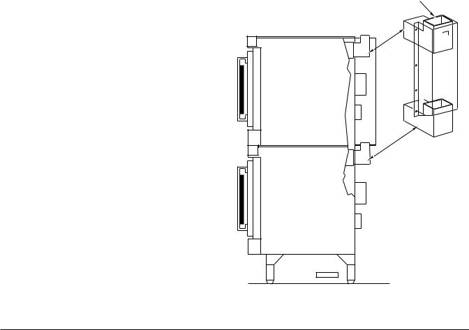
STACKING FLUE
ASSEMBLING STACKED OVENS |
|
Unpack the ovens and the stack kit. Position |
|
the oven to be used as the bottom oven on |
|
its left side for access to the oven bottom, |
|
taking care not to scratch or damage it. |
|
Attach the four leg assemblies with the 24 |
|
bolts and lockwashers (6 per leg). |
|
Place the lower oven (with legs) on the floor |
|
and remove two 7⁄16" (11 mm) diameter |
|
knockouts on each side of the top cover. |
|
Install two locating studs to the bottom of the |
|
top oven per stacking kit instructions. |
|
Move the oven with legs to the installed |
|
position. Place the upper oven on top of the |
|
lower oven using the locating studs. |
|
Remove the optional rear panel, if provided, |
|
from the TOP oven. Install the Stacking Flue |
|
(Fig. 3) with the four screws provided. |
|
Replace the top oven rear panel, if provided. |
PL-53463 |
Fig. 3
– 5 –
 Loading...