


SCC264
Read these instructions before using the machine
Lea las instrucciones antes de utilizar la máquina
MODELS: SC264
10052210
SCC264
10052250
Operating Instructions (ENG)
Instrucciones de funcionamiento (SPA)
86039070 02/20/09
PR V NO. 98963
BM
WALK BEHIND SCRUBBER
IPX4

MACHINE DATA LOG/OVERVIEW
CUTTER 24V 86039070 04/10/07
2
For the name and address of your dealer contact: Windsor Industries
YOUR DEALER
Name: __________________________________________________________________________________________________
Address: _______________________________________________________________________________________________
Phone Number: _________________________________________________________________________________________
OVERVIEW
The Saber Cutter is a battery powered, self-propelled, hard floor scrubber intended for
commercial use. The appliance applies a cleaning solution onto a hard floor, scrubs the floor
with brushes or pads, and then vacuums the soiled water back into the recovery tank.
MODEL _______________________________________
DATE OF PURCHASE __________________________
SERIAL NUMBER ______________________________
SALES REPRESENTATIVE # _____________________
DEALER NAME ________________________________
OPERATIONS GUIDE NUMBER ___________________
PUBLISHED
__________________________________________
Copyright 2002 Windsor Industries, Printed in USA

TABLE OF CONTENTS
CUTTER 24V 86039070 04/10/07
3
Machine Data Log/Overview.........................2
Table of Contents..........................................3
HOW TO USE THIS MANUAL
How to use this Manual.................................1-1
SAFETY
Important Safety Instructions........................2-1
Hazard Intensity Level. .................................2-2
Safety Label Location. ..................................2-3
OPERATIONS
Technical Specifications. ..............................3-1
How the Machine Works...............................3-3
Components..................................................3-4
Controls.........................................................3-5
Machine Operation........................................3-9
Pre-Run Machine Inspection......................3-9
Starting Machine........................................3-9
Emergency Stop Procedures.....................3-9
Filling the Solution Tank.............................3-9
Scrubbing................................................ 3-10
Emptying & Cleaning Tanks.................... 3-11
MAINTENANCE
Service Schedule.............................. ........ 4-1
Batteries........................................................4-3
Battery Maintenance..................................4-3
Checking Battery Specific Gravity..............4-4
Charging the Batteries...............................4-4
Changing Batteries. ...................................4-5
Battery Connections...................................4-5
Squeegee Blades..........................................4-6
Adjusting Squeegee......................................4-6
Replace or Rotate Rear Squeegee Blade.. ..4-6
Replace or Rotate Front Squeegee Blade. ..4-6
Adjusting Squeegee Pitch................. ........ ..4-7
Adjusting Rear Deflection. ................ ........ ..4-7
Replacing Aqua-Mizer Squeege Blades.......4-7
Scrub Brushes. .............................................4-8
Types.........................................................4-8
Replacing or Installing Scrub Brushes.......4-8
Float Shut-Off................................................4-8
Solution Strainer ...........................................4-9
Brush Motor Replacement............................4-9
Traction Motor Brush Replacement.. .........4-10
Circuit Breaker.................................. .........4-10
Brush Shrouds & Brush Skirts.......... .........4-10
Vacuum Motor .................................. .........4-11
Greasing Instructions........................ .........4-12
Machine Troubleshooting ................. .........4-13
GROUP PARTS LIST
Control Handle............................................ 5-1
Cover (Front) & Tank Mount....................... 5-3
Cover (Top) & Tank Mount......................... 5-5
Decal........................................................... 5-7
Electrical Panel........................................... 5-9
Lift Handle................................................... 5-11
Lift Handle Linkage..................................... 5-13
Recovery Tank............................................ 5-15
Scrub Brush/Pad Driver.............................. 5-17
Scrub Deck Aqua-Mizer-26 in Scrubhead .. 5-19
Scrub Deck Motors..................................... 5-21
Scrub Deck Skirt......................................... 5-23
Scrub Deck Lift Linkage-26 in Scrubhead .. 5-25
Scrub Deck Lift-Center ............................... 5-27
Scrub Deck Lift Linkage-Front & Rear........ 5-29
Solution....................................................... 5-31
Squeegee-26 in Scrubhead........................ 5-35
Squeegee Lift Linkage (Lower)................... 5-37
Vacuum....................................................... 5-39
Wheels & Frame......................................... 5-41
Wiring-Battery............................................. 5-43
Wiring-Control Panel................................... 5-45
Wiring-Main Harness.................................. 5-47
Wiring-Schematic-SC264 ........................... 5-49
Wiring-Schematic-SCC264......................... 5-50
Brake-Option............................................... 5-51
Emergency Stop-Option ............................. 5-53
Accessory Pump-Option............................. 5-55
Battery Charger- SCC264........................... 5-57
Suggested Spare Parts............................... 5-59
EC Declaration of Conformity..................... 5-60
Warranty..................................................... 5-61
HOW TO USE THIS MANUAL
CUTTER 24V 86039070 04/10/07
1-1
This manual contains the following sections:
- HOW TO USE THIS MANUAL
- SAFETY
- OPERATIONS
- MAINTENANCE
- PARTS LIST
The HOW TO USE THIS MANUAL section will tell
you how to find important information for ordering
correct repair parts.
Parts may be ordered from authorized Windsor
dealers.
When placing an order for parts, the
machine model and machine serial number are
important. Refer to the MACHINE DATA box which
is filled out during the installation of your machine.
The MACHINE DATA box is located on the inside of
the front cover of this manual.
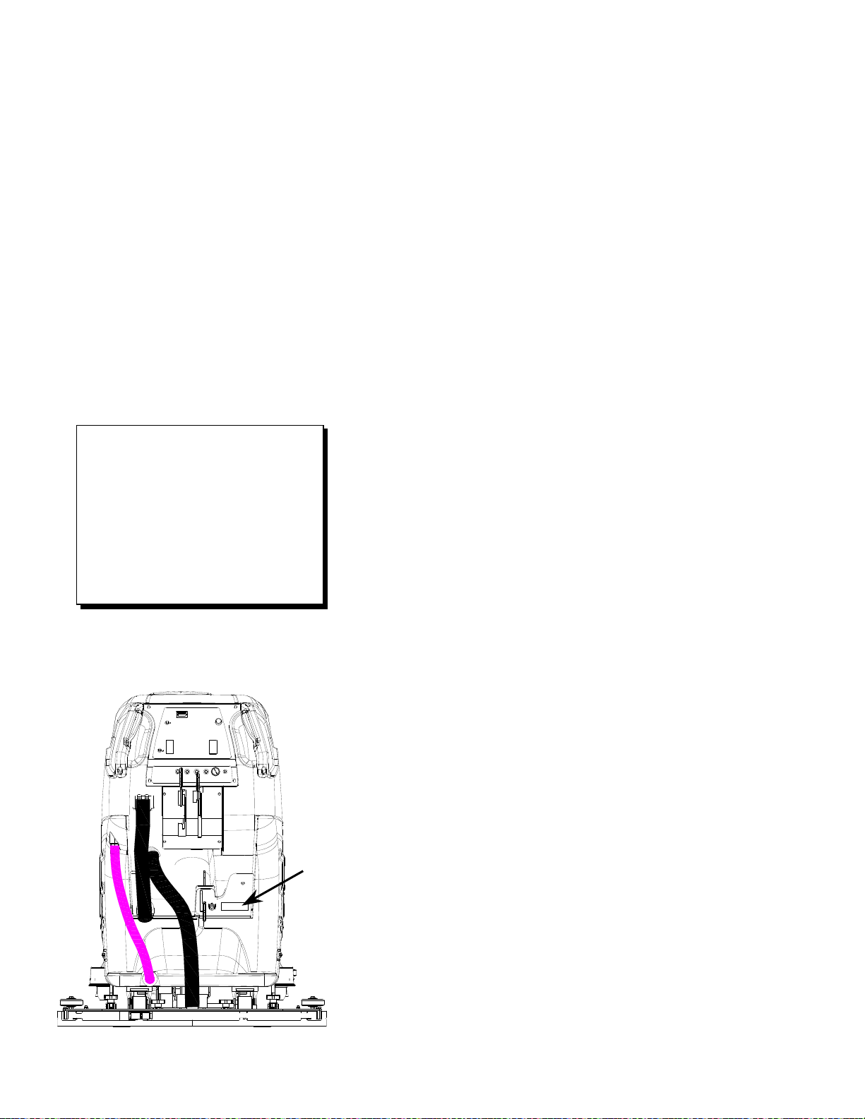
The model and serial number of your machine is on
the back panel of the machine.
The SAFETY section contains important information
regarding hazard or unsafe practices of the
machine. Levels of hazards are identified that could
result in product or personal injury, or severe injury
resulting in death.
The OPERATIONS section is to familiarize the
operator with the operation and function of the
machine.
The MAINTENANCE section contains preventive
maintenance to keep the machine and its
components in good working condition. They are
listed in this general order:
- Batteries
- Scrub Brushes
- Adjusting Squeegee
- Scrub Deck Skirts
- Squeegee Blade
- Service Schedule
The PARTS LIST section contains assembled parts
illustrations and corresponding parts list. The parts
lists include a number of columns of information:
- REF – column refers to the reference
number on the parts illustration.
- PART NO. – column lists the part
number for the part.
- PRV NO. – reference number
- QTY – column lists the quantity of the
part used in that area of the machine.
- DESCRIPTION – column is a brief
description of the part.
- SERIAL NO. FROM – column indicates
the first machine the part number is
applicable to. When the machine design
has changed, this column will indicate
serial number of applicable machine.
The main illustration shows the most
current design of the machine. The
boxed illustrations show older designs. If
column has an asterisk (*), call
manufacturer for a serial number.
- NOTES – column for information not
noted by the other columns.
NOTE: If a service or option kit is installed on your
machine, be sure to keep the KIT INSTRUCTIONS
which came with the kit. It contains replacement
parts numbers needed for ordering future parts.
MODEL _____________________________________
DATE OF PURCHASE ________________________
SERIAL NUMBER ____________________________
SALES REPRESENTATIVE # ___________________
DEALER NAME ______________________________
OPERATIONS GUIDE NUMBER __________________
PUBLISHED ________________________________
Copyright 2002 Windsor Industries, Printed in USA

CUTTER 24V 86039070 04/10/07
2-1
IMPORTANT SAFETY INSTRUCTIONS
When using an battery powered appliance, basic precaution
must always be followed, including the following:
READ ALL INSTRUCTIONS BEFORE USING THIS MACHINE.
To reduce the risk of fire, electric shock, or injury:
Use only indoors. Do not use outdoors or expose to rain.
Use only as described in this manual. Use only manufacturer’s recommended components and
attachments.
If the machine is not working properly, has been dropped, damaged, left outdoors, or dropped into
water, return it to an authorized service center.
Do not operate the machine with any openings blocked. Keep openings free of debris that may reduce
airflow.
This machine is not suitable for picking up hazardous dust.
Machine can cause a fire when operating near flammable vapors or materials. Do not operate this
machine near flammable fluids, dust or vapors.
This machine is suitable for commercial use, for example in hotels, schools, hospitals,
factories, shops and offices for more than normal housekeeping purposes.
Maintenance and repairs must be done by qualified personnel.
If foam or liquid comes out of machine, switch off immediately.
Disconnect battery before cleaning or servicing.
Before the machine is discarded, the batteries must be removed and properly disposed of.
Make sure all warning and caution labels are legible and properly attached to the machine.
During operation, attention shall be paid to other persons, especially children.
Before use all covers and doors shall be put in the positions specified in the instructions.
When leaving unattended, secure against unintentional movement.
The machine shall only be operated by instructed and authorized persons.
When leaving unattended, switch off or lock the main power switch to prevent unauthorized use.
Only chemicals recommended by the manufacturer shall be used.
This appliance has been designed for use with the brushes specified by the manufacturer. The fitting
of other brushes may affect its safety.
Do not use on surfaces having a gradient exceeding 2% unless the optional parking brake is installed
on the machine.
SAVE THESE INSTRUCTIONS
!
WARNING:

HAZARD INTENSITY LEVEL
CUTTER 24V 86039070 04/10/07
2-2
The following symbols are used throughout this guide as indicated in their descriptions:
HAZARD INTENSITY LEVEL
There are three levels of hazard intensity identified by signal words -WARNING and CAUTION and FOR
SAFETY. The level of hazard intensity is determined by the following definitions:
WARNING - Hazards or unsafe practices which COULD result in severe personal injury or death.
CAUTION - Hazards or unsafe practices which could result in minor personal injury or product or property
damage.
FOR SAFETY: To Identify actions which must be followed for safe operation of equipment.
Report machine damage or faulty operation immediately. Do not use the machine if it is not in proper
operating condition. Following is information that signals some potentially dangerous conditions to the
operator or the equipment. Read this information carefully. Know when these conditions can exist. Locate
all safety devices on the machine. Please take the necessary steps to train the machine operating
personnel.
FOR SAFETY:
DO NOT OPERATE MACHINE:
Unless Trained and Authorized.
Unless Operation Guide is Read and understood.
In Flammable or Explosive areas.
In areas with possible falling objects.
WHEN SERVICING MACHINE:
Avoid moving parts. Do not wear loose clothing; jackets, shirts, or sleeves when working on the
machine. Use Windsor approved replacement parts.
Batteries emit hydrogen gas. Explosion or fire can result. Keep sparks and open flame away. Keep
top cover in raised position when charging. Keep sparks and flames away from the batteries. Do
not smoke around batteries.
Disconnect batteries before working on machine. Only qualified personnel should work inside
machine. Always wear eye protection and protective clothing when working on or near batteries.
Avoid skin contact with the acid contained in the batteries.
Never allow metal to lie across battery tops.
! WARNING
! WARNING
! WARNING
! WARNING
! CAUTION
SAFETY LABEL LOCATION
CUTTER 24V 86039070 04/10/07
2-3
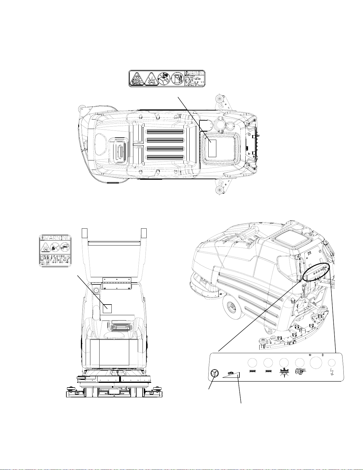
NOTE: These drawings indicate the location of safety labels on the machine. If at any time the labels become
illegible, promptly replace them.
CIRCUIT BREAKER DECAL
86243530
PRV NO. 500565
2% GRADE WARNING
SEE MANUAL
SAFETY DECAL
86252530
PRV NO. 81494
BATTERY CAUTION
86252520
PRV NO. 80885

TECHNICAL SPECIFICATIONS
CUTTER 24V 86039070 04/10/07
3-1
ITEM DIMENSION/CAPACITY
Nominal power 1450 W
Rated Voltage 24VDC
Rated Amperage 60 Amps
Batteries 4 X 6 Volt 250-305-335 AH @
20 hr rate
Scrub Brush Motors 2 X .75 hp (0.56 kW)
Vacuum Motor .75 hp (0.56 Kw)
Propelling Motor .3 hp (0.22 Kw)
Mass (GVW) 915 lbs. (415 kg) with 335 AH
Weight empty without batteries 346 lbs. (157 kg)
Solution Control Gravity feed, fully variable with
automatic shut-off in neutral
Solution tank capacity 23 gal. (87 l)
Recovery tank capacity 25 gal. (95 l)
Scrub brush diameter for 26 in. (66 cm) scrub head 13 in (33.0 cm)
Scrub brush pressure Mechanical 80 lbs. (356N)
Floating 130 lbs. (578N)
restricted
Scrub brush speed 200 rpm
Tires 2 x 10 in (25.4 cm) non-marking
foam-filled
Casters 2 X 4 in (10.2 cm) polyurethane
solid non-marking
Foundation Pressure 21 lbs./in
2
(140 kPa)
Maximum Speed 3.2 Miles/hour (5.2 km/hour)
Coverage with 26 in. (66 cm) scrub head 31,680 ft
2
/hour at 3.0 mph with
2 in. overlap*
Frame Construction Steel plate with epoxy
powdercoat finish.
Brakes (optional) Tire lock parking brake
Minimum aisle u-turn width with 26 in. (66 cm) scrub head 69 in. (175 cm)
Maximum rated climb and descent angle with empty tanks
and without optional parking brake
2%
Maximum rated climb and descent angle with full tanks
and without optional parking brake
2%
* Cleaning rate results will vary depending on floor type, building structure, etc.
TECHNICAL SPECIFICATIONS
CUTTER 24V 86039070 04/10/07
3-2
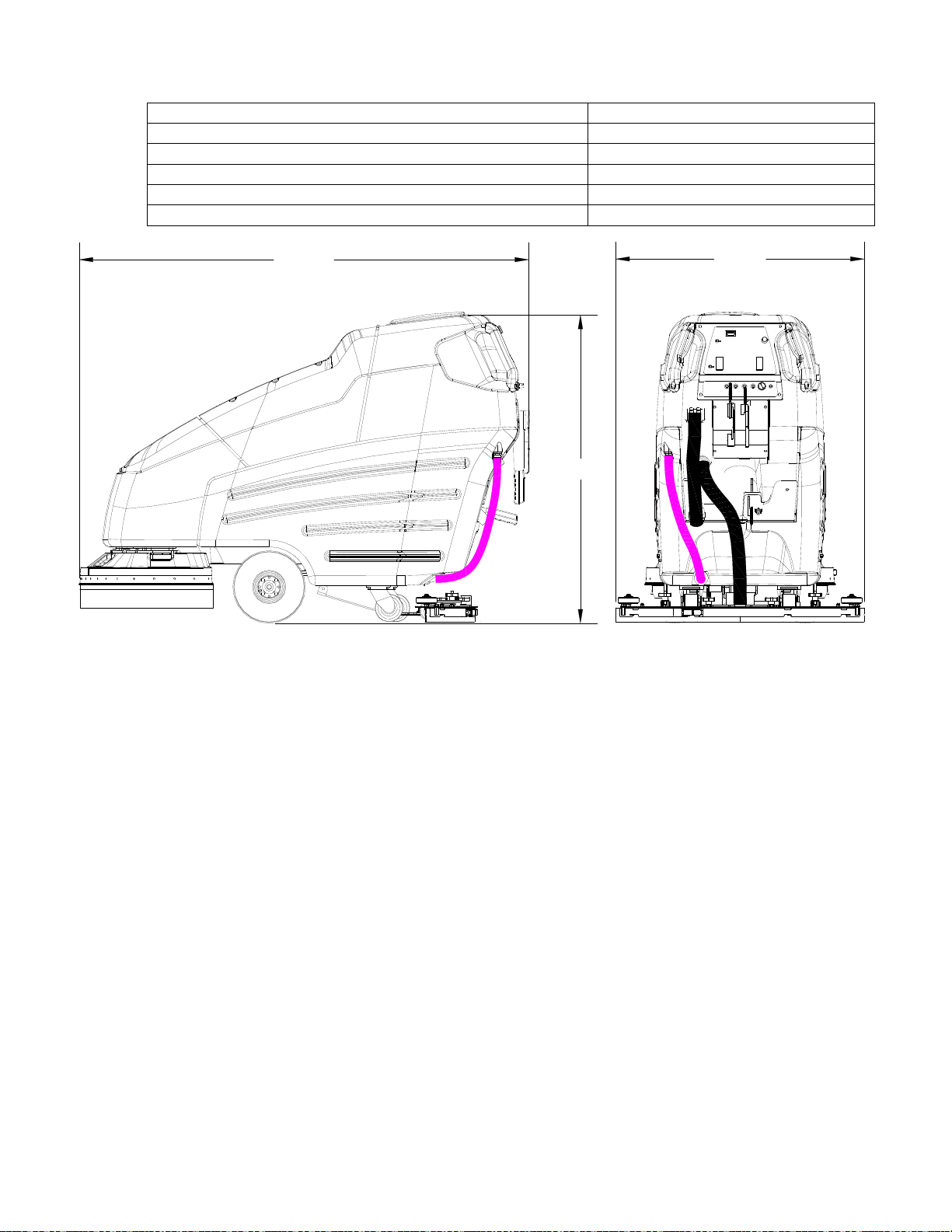
ITEM MEASURE
Height 45 in. (114 cm)
Length with 26 in. (66 cm) scrub head 64 in. (163 cm)
Width without squeegee and scrub head 24 in. (61 cm)
Width of squeegee for 26 in. (66 cm) scrub head 35 in. (89 cm)
Width of scrub path for 26 in. (66 cm) scrub head 26 in. (66 cm)
SPECIAL NOTES:
The sound pressure level at the operator’s ear
was measured to be 72 dBA. This was a
nearfield, broad-band measurement taken in a
typical industrial environment on a tile floor.
This appliance contains no possible source of
impact noise. The instantaneous sound
pressure level is below 63 Pa.
The weighted root mean square acceleration at
the operator’s arms was measured to be below
2.5m/s
2
. This was a tri-axial, third-octave-band
measurement made during normal operation on
a composite tile floor. The measurement and
related calculations were made in accordance
with ANSI S3.34-1986.
Length
Width
Height

HOW THE MACHINE WORKS
CUTTER 24V 86039070 04/10/07
3-3
The Saber Cutter is a battery powered, self-
propelled, hard floor scrubber intended for
commercial use. The appliance applies a
cleaning solution onto a hard floor, scrubs the
floor with brushes, and then vacuums the soiled
water back into the recovery tank.
The machine's primary systems are the solution
system, scrub system, recovery system, and
directional control system.
The function of the solution system is to store
cleaning solution and deliver it to the scrub
system. The solution system consists of the
solution tank, strainer, valve and controls. The
solution tank stores cleaning solution (water and
detergent) until it is delivered to the scrub system.
The strainer protects the valve from debris. The
valve is a solenoid type valve, which controls the
delivery of cleaning solution to the scrub system.
The valve automatically prevents solution flow
unless the scrub brushes are turned on and the
machine is being propelled. The solution control
knob controls the amount of cleaning solution
delivered to the scrub system by controlling the
amount of time the valve is open.
The function of the scrub system is to scrub the
floor. The scrub system consists of two rotary
type disk scrub brushes, motors, scrub deck skirt,
lift mechanism and controls. The brushes scrub
the floor and the motors drive the brushes. The
brush drive hubs allow the scrub brushes to follow
irregularities and changes in the floor without
loosing contact with floor. The scrub deck skirt
controls the cleaning solution on the floor so that
the squeegee can pick it up. The brush lever is
used to raise and lower the deck. For heavy scrub
pressure lock the lever into the lower notch.
Pushing the lever forward allows you to push
down. Pull Back on the lever to allow it to swing
down and out of the way.
The function of the recovery system is to vacuum
the soiled water back into the recovery tank. The
recovery system consists of the squeegee,
vacuum motor, float ball filter, recovery tank and
controls. The squeegee wipes the dirty solution
off the floor as the machine moves forward. The
vacuum motor provides suction to draw the dirty
solution off the floor and into the recovery tank.
The recovery tank stores the dirty solution. The
float ball filter protects the vacuum fan from debris
and shuts off air going to the recovery tank when
tank is full.
When flow of air is shut off the vacuum motor will
continue to run. At this time the recovery tank
must be drained.
The function of the directional control system is to
control the direction and speed of the machine.
The directional control system consists of the
propel control buttons, reverse button, speed
control knob/potentiometer, controller and
transaxle. The propel control buttons actuates
switches, which signal forward pressing the
reverse button in addition to one of the propel
control buttons the machine will move in reverse.
The speed control knob actuates a potentiometer,
which signals speed. The controller interprets the
forward/reverse signals from the switches and the
speed signal from the potentiometer to command
the transaxle to propel the machine in the
direction, and at the speed, desired.
 Loading...