


Windsor SG32, 10052470, 10052460, SG28, 10052450 User Manual
...SCRUBBER |
|
|
|
|
|
|
Operating Instructions (ENG) |
MODELS: |
SG28 |
SG32 |
SG36 |
|
10052450 |
10052460 |
10052470 |
AFTER SN: 1000136404 |
|
|
|
IPX4
Read these instructions before using the machine
N
86037580 02/10/09
PRV NO. 980207

MACHINE DATA LOG/OVERVIEW
MODEL _______________________________________
DATE OF PURCHASE __________________________
SERIAL NUMBER ______________________________
SALES REPRESENTATIVE # _____________________
DEALER NAME ________________________________
OPERATIONS GUIDE NUMBER ___________________
PUBLISHED __________________________________________
YOUR DEALER
Name: __________________________________________________________________________________________________
Address: _______________________________________________________________________________________________
For the name and address of your dealer contact: Windsor Industries
Phone Number: _________________________________________________________________________________________
OVERVIEW
The Saber Glide is a battery powered, ride-on, hard floor scrubber intended for commercial use. The appliance applies a cleaning solution onto a hard floor, scrubs the floor with brushes or pads, and then vacuums the soiled water back into the recovery tank.
2 |
86037580 GLIDE 01/03/07 |
|
Machine Data Log/Overview................................ |
2 |
Table of Contents................................................. |
3 |
HOW TO USE THIS MANUAL |
|
How to use this Manual........................................ |
1-1 |
SAFETY |
|
Important Safety Instructions ............................... |
2-1 |
Hazard Intensity Level.......................................... |
2-2 |
Safety Label Location........................................... |
2-3 |
OPERATIONS |
|
Technical Specifications....................................... |
3-1 |
How the Machine Works. ..................................... |
3-3 |
Components......................................................... |
3-4 |
Controls................................................................ |
3-5 |
Machine Operation............................................ |
3-14 |
Pre-Run Machine Inspection ......................... |
3-14 |
Starting Machine. ........................................... |
3-14 |
Filling the Solution Tank................................. |
3-14 |
Scrubbing. ...................................................... |
3-14 |
Emergency Stop Procedures ......................... |
3-15 |
Emptying & Cleaning Tanks........................... |
3-16 |
MAINTENANCE |
|
Maintenance............................................ ............ |
4-1 |
Batteries. .............................................................. |
4-2 |
Battery Maintenance. ........................................... |
4-2 |
Checking Battery Specific Gravity..................... |
4-2 |
Charging the Batteries. ..................................... |
4-3 |
Changing Batteries............................................ |
4-4 |
Battery Connections.......................................... |
4-4 |
Battery Tray Drain Hose.................................... |
4-4 |
Squeegee............................................................. |
4-5 |
Adjusting Pitch .................................................. |
4-5 |
Replace/Rotate Rear Squeegee Blade............. |
4-6 |
Removing Squeegee Assembly........................ |
4-6 |
Replace/Rotate Front Squeegee Blade ............ |
4-6 |
Side Squeegee.................................................. |
4-7 |
Replace/Rotate Side Squeegee Blades............ |
4-7 |
Adjusting the Side Squeegee Deflection........... |
4-7 |
Scrub Brush Replacement ................................... |
4-8 |
Brake.................................................................... |
4-9 |
Steering Chain Tensioner .................................... |
4-9 |
Vacuum Motor................................................... |
4-10 |
Brush Motor....................................................... |
4-11 |
Traction Motor ................................................... |
4-12 |
Fuse .................................................................. |
4-12 |
Circuit Breakers................................................. |
4-12 |
Squeegee Actuator ........................................... |
4-13 |
Scrub Deck Actuator ......................................... |
4-14 |
Transporting Machine ....................................... |
4-15 |
Jacking Machine ............................................... |
4-16 |
TABLE OF CONTENTS
Service Schedule. ............................................. |
4-17 |
Machine Troubleshooting.................................. |
4-18 |
GROUP PARTS LIST |
|
Brake. ................................................................... |
5-1 |
Circuit Breaker...................................................... |
5-3 |
Control Panel........................................................ |
5-5 |
Decal. ................................................................... |
5-7 |
Front Bumper & Floor........................................... |
5-9 |
Fwd/Rev Pedal .................................................. |
5-11 |
Scrub Brush/Driver ............................................ |
5-13 |
Scrub Deck-28 in Disk....................................... |
5-15 |
Scrub Deck Side Squeegee-28 in Disk............. |
5-17 |
Scrub Deck Lift-28 & 32 in................................. |
5-19 |
Scrub Deck-32 in............................................... |
5-21 |
Scrub Deck Side Squeegee-32 in ..................... |
5-23 |
Scrub Deck-36 in Main...................................... |
5-25 |
Scrub Deck-36 in Retractable ........................... |
5-27 |
Scrub Deck Side Squeegee-36 in ..................... |
5-29 |
Scrub Deck Lift-36 in ......................................... |
5-31 |
Seat & Side Cover............................................. |
5-33 |
Solution Delivery ............................................... |
5-35 |
Squeegee-28 in & 36 in..................................... |
5-37 |
Squeegee –32 in ............................................... |
5-39 |
Squeegee Lift .................................................... |
5-41 |
Steering-Upper .................................................. |
5-43 |
Steering-Lower .................................................. |
5-45 |
Tank .................................................................. |
5-47 |
Tank Cover........................................................ |
5-49 |
Vacuum ............................................................. |
5-51 |
Wheel & Frame ................................................. |
5-53 |
Wiring-Battery.................................................... |
5-55 |
Wiring-Main Harness......................................... |
5-57 |
Wiring-Main Harness Connection ..................... |
5-59 |
Wiring-Control Panel Group .............................. |
5-61 |
Wiring-Drive Motor ............................................ |
5-63 |
Wiring Diagram.................................................. |
5-65 |
Suggested Spare Parts ..................................... |
5-66 |
Accessory Pump-Option.................................... |
5-67 |
Back-Up Alarm-Option ...................................... |
5-69 |
Dual Vacuum Motor-Option............................... |
5-71 |
Warning Light-Option ........................................ |
5-73 |
EC Declaration of Conformity............................ |
5-75 |
Serial Numbers.................................................. |
5-78 |
Warranty |
|
3
86037580 GLIDE 11/05/08
HOW TO USE THIS MANUAL
This manual contains the following sections: |
The SAFETY section contains important information |
|
|
|
regarding hazard or unsafe practices of the |
- HOW TO USE THIS MANUAL |
machine. Levels of hazards are identified that could |
|
- |
SAFETY |
result in product or personal injury, or severe injury |
- |
OPERATIONS |
resulting in death. |
- |
MAINTENANCE |
The OPERATIONS section is to familiarize the |
||
- |
PARTS LIST |
|||
operator with the operation and function of the |
||||
|
|
|||
The HOW TO USE THIS MANUAL section will tell |
machine. |
|
||
|
|
|||
you how to find important information for ordering |
The MAINTENANCE section contains preventive |
|||
correct repair parts. |
maintenance to keep the machine and its |
|||
Parts may be ordered from authorized Windsor |
components in good working condition. They are |
|||
listed in this general order: |
||||
dealers. When placing an order for parts, the |
|
|
||
machine model and machine serial number are |
- |
Batteries |
||
important. Refer to the MACHINE DATA box which |
||||
- |
Scrub Brushes |
|||
is filled out during the installation of your machine. |
||||
- |
Adjusting Squeegee |
|||
The MACHINE DATA box is located on the inside of |
||||
- |
Service Schedule |
|||
the front cover of this manual. |
||||
- |
Machine Troubleshooting |
|||
|
|
|||
MODEL _____________________________________ |
The PARTS LIST section contains assembled parts |
|||
DATE OF PURCHASE ________________________ |
illustrations and corresponding parts list. The parts |
|||
SERIAL |
NUMBER ____________________________ |
lists include a number of columns of information: |
||
SALES REPRESENTATIVE # ___________________ |
- |
REF – column refers to the reference |
||
|
|
|||
DEALER |
NAME ______________________________ |
|
number on the parts illustration. |
|
|
|
|
||
OPERATIONS GUIDE NUMBER __________________ |
- |
PRV NO. –Reference No. |
||
|
|
- PART NO. – column lists the part |
||
PUBLISHED ________________________________ |
|
number for the part. |
||
|
|
|
||
|
Copyright 2002 Windsor Industries, Printed in USA |
- |
QTY – column lists the quantity of the |
|
|
|
|
part used in that area of the machine. |
|
The model and serial number of your machine are |
- DESCRIPTION – column is a brief |
|||
|
description of the part. |
|||
located to the front of the battery compartment for |
|
|||
- |
SERIAL NO. FROM – If this column has |
|||
the machine. |
||||
|
an (*) and a Reference number, see the |
|||
|
|
|
SERIAL NUMBERS page in the back of |
|
|
|
|
your manual. If column has two asterisk |
|
|
|
|
(**), call manufacturer for serial number. |
|
|
|
|
The serial number indicates the first |
|
|
|
|
machine the part number is applicable |
|
|
|
|
to. The main illustration shows the most |
|
|
|
|
current design of the machine. When a |
|
|
|
|
boxed illustration is shown, it displays |
|
|
|
|
the older design. |
|
|
|
- NOTES – column for information not |
||
|
|
|
noted by the other columns. |
|
|
|
NOTE: If a service or option kit is installed on your |
||
|
|
machine, be sure to keep the KIT INSTRUCTIONS |
||
|
|
which came with the kit. It contains replacement |
||
|
|
parts numbers needed for ordering future parts. |
||
|
|
NOTE: The number on the lower left corner of the |
||
|
|
front cover is the part number for this manual. |
||
1-1 |
86037580 GLIDE 11/05/08 |
|
||
|
|
|
||

IMPORTANT SAFETY INSTRUCTIONS
When using an battery powered appliance, basic precaution must always be followed, including the following:
READ ALL INSTRUCTIONS BEFORE USING THIS MACHINE.
! WARNING: To reduce the risk of fire, electric shock, or injury:
Use only indoors. Do not use outdoors or expose to rain.
Use only as described in this manual. Use only manufacturer’s recommended components and attachments.
If the machine is not working properly, has been dropped, damaged, left outdoors, or dropped into water, return it to an authorized service center.
Do not operate the machine with any openings blocked. Keep openings free of debris that may reduce airflow.
This machine is not suitable for picking up hazardous dust.
Machine can cause a fire when operating near flammable vapors or materials. Do not operate this machine near flammable fluids, dust or vapors.
This machine is suitable for commercial use, for example in hotels, schools, hospitals, factories, shops and offices for more than normal housekeeping purposes.
Maintenance and repairs must be done by qualified personnel.
If foam or liquid comes out of machine, switch off immediately.
Disconnect battery before cleaning or servicing.
Before the machine is discarded, the batteries must be removed and properly disposed of. Make sure all warning and caution labels are legible and properly attached to the machine.
During operation, attention shall be paid to other persons, especially children.
Before use all covers and doors shall be put in the positions specified in the instructions.
When leaving unattended, secure against unintentional movement.
The machine shall only be operated by instructed and authorized persons.
When leaving unattended, switch off or lock the main power switch to prevent unauthorized use.
Only chemicals recommended by the manufacturer shall be used.
This appliance has been designed for use with the brushes specified by the manufacturer. The fitting of other brushes may affect its safety.
SAVE THESE INSTRUCTIONS
86037580 GLIDE 01/03/07 |
2-1 |
|

HAZARD INTENSITY LEVEL
The following symbols are used throughout this guide as indicated in their descriptions:
HAZARD INTENSITY LEVEL
There are three levels of hazard intensity identified by signal words -WARNING and CAUTION and FOR SAFETY. The level of hazard intensity is determined by the following definitions:

 !
!
WARNING - Hazards or unsafe practices which COULD result in severe personal injury or death.

 !
!


CAUTION - Hazards or unsafe practices which could result in minor personal injury or product or property damage.
FOR SAFETY: To Identify actions which must be followed for safe operation of equipment.
Report machine damage or faulty operation immediately. Do not use the machine if it is not in proper operating condition. Following is information that signals some potentially dangerous conditions to the operator or the equipment. Read this information carefully. Know when these conditions can exist. Locate all safety devices on the machine. Please take the necessary steps to train the machine operating personnel.
FOR SAFETY:
DO NOT OPERATE MACHINE:
Unless Trained and Authorized.
Unless Operation Guide is Read and understood.
In Flammable or Explosive areas.
In areas with possible falling objects.
WHEN SERVICING MACHINE:
Avoid moving parts. Do not wear loose clothing; jackets, shirts, or sleeves when working on the machine. Use Windsor approved replacement parts.

 !
!


Batteries emit hydrogen gas. Explosion or fire can result. Keep sparks and open flame away. Keep solution tank in raised position when charging. Keep sparks and flames away from the batteries. Do not smoke around batteries.

 !
!


Disconnect batteries before working on machine. Only qualified personnel should work inside machine. Always wear eye protection and protective clothing when working on or near batteries. Avoid skin contact with the acid contained in the batteries.

 !
!


Never allow metal to lie across battery tops.
2-2 |
86037580 GLIDE 01/03/07 |
|

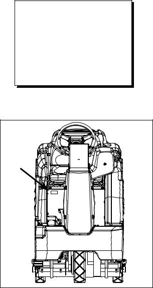
SAFETY LABEL LOCATION
NOTE: These drawings indicate the location of safety labels on the machine. If at any time the labels become illegible, promptly replace them.
SAFETY DECAL 86252530
PRV NO. 81494
BATTERY CAUTION 86252520 PRV NO. 80885
CIRCUIT BREAKER 8624413028 IN & 32 IN PRV NO. 500859 8624414036 IN
PRV NO. 500861
HORN DECAL 86248210 PRV NO. 81349
|
PINCH POINT WARNING |
|
36 IN MODEL ONLY |
PINCH POINT WARNING |
86243830 |
86243830 (2) |
PRV NO. 500663 |
PRV NO. 500663 |
|
86037580 GLIDE 01/03/07 |
2-3 |
|
TECHNICAL SPECIFICATIONS
ITEM |
DIMENSION/CAPACITY |
Nominal power |
2.9 kW |
Rated Voltage |
36 Volts DC |
Rated Amperage |
80 amps (28in & 32in) |
|
95 amps (36in) |
Batteries |
6 x 6 Volt 250-335 AH @20 hr. rate |
Scrub Brush Motors |
2 x 1.0 HP (746 W) 28in & 32in |
|
3 x 1.0 HP (746 W) 36in |
Vacuum Motor(s) |
1 x .75 HP (560 W) Standard, second motor |
|
optional |
Propelling Motor |
1.3 HP (932 W) |
Mass (GVW) |
1810 lbs (820 kg) 28in & 32in |
|
1840 lbs (835kg) 36in |
Weight empty without batteries |
790 lbs (360 kg) 28in & 32in |
|
825 lbs (375 kg) 36in |
Solution Control |
Gravity feed, fully variable with automatic shut |
|
off in neutral |
Solution tank capacity |
30 gal (115 L) |
Recovery tank capacity |
30 gal (115 L) |
Scrub brush diameter for 28 in. (71 cm) disk scrub head |
14 inch (35.5 cm) |
Scrub brush diameter for 32 in. (81 cm) disk scrub head |
16 inch (40.6 cm) |
Scrub brush diameter for 36 in. (91 cm) disk scrub head |
12 inch (30.5 cm) |
Scrub brush pressure |
0-225 lbs (0-1000N) 28in & 32in |
|
0-150 lbs (0-667N) 36in |
Scrub brush speed |
300 rpm |
Tires |
12 in. (30.5 cm) Solid Scrubber Compound |
Foundation Pressure |
108 lbs./in² (745 kPa) |
Maximum Speed |
4.1 miles/hour (6.5 Km/hour) |
Coverage with 28 in. (71 cm) scrub head |
42,328 ft²/hr @ 3.7 mph with 2 in. overlap |
Coverage with 32 in. (81 cm) scrub head |
48,840 ft²/hr @ 3.7 mph with 2 in. overlap |
Coverage with 36 in. (91 cm) scrub head |
55,352 ft²/hr @ 3.7 mph with 2 in. overlap |
Frame Construction |
Powder coated steel |
Brakes |
Self centering mechanical 7 in. (17.7 cm) disc |
|
with hand lock parking brake |
Minimum aisle u-turn width with 28 in. (71 cm), 32 in. (81 cm) or |
66 inches (168 cm) |
36 in. (91 cm) disk scrub head |
|
Maximum rated climb and descent angle |
7.5 degrees |
3-1 |
86037580 GLIDE 01/03/07 |
|
|
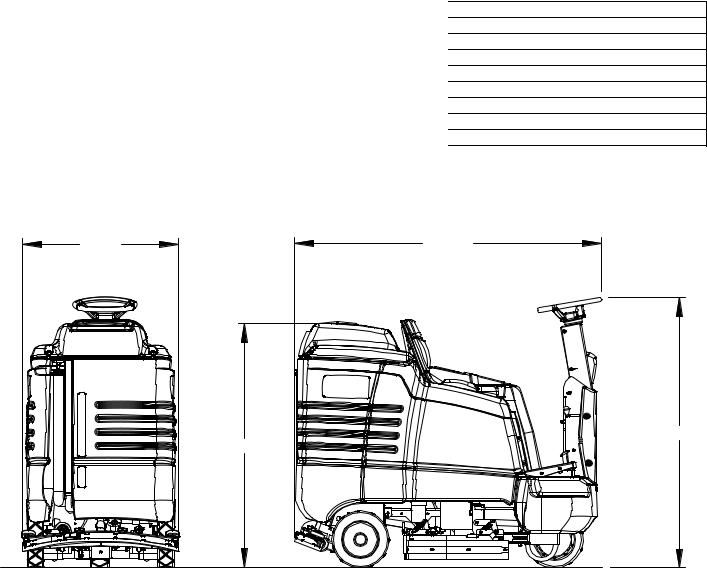
TECHNICAL SPECIFICATIONS |
|
|
|
MEASURE |
ITEM |
|
|
Height 1 |
|
51 inches (130 cm) |
Height 2 |
|
56.6 inches (144 cm) |
Length |
|
63.5 inches (161 cm) |
Width without squeegee and scrub head |
|
31 inches (79 cm) |
Width of squeegee |
|
33 inches (84 cm) |
Width of scrub path for 28 in. (71 cm) |
|
28 inches (71 cm) |
Width of scrub path for 32 in. (81 cm) |
|
32 inches (81 cm) |
Width of scrub path for 36 in. (91 cm) |
|
28-36 inches (71-91 cm) |
WIDTH |
LENGTH |
HEIGHT 2
HEIGHT 1
SPECIAL NOTES:
The sound pressure level at the operator’s ear was measured to be 72.3 dBA. This was a nearfield, broadband measurement taken in a typical industrial environment on a tile floor. This appliance contains no possible source of impact noise. The instantaneous sound pressure level is below 63 Pa.
The weighted root mean square acceleration at the operator’s arms was measured to be below 2.5m/s2. This was a tri-axial, third-octave-band measurement made during normal operation on a composite tile floor. The measurement and related calculations were made in accordance with ANSI S3.34-1986.
86037580 GLIDE 01/03/07 |
3-2 |
|
HOW THE MACHINE WORKS
The Saber Glide is a battery powered, selfpropelled, hard floor scrubber intended for commercial use. The appliance applies a cleaning solution onto a hard floor, scrubs the floor with brushes, and then vacuums the soiled water back into the recovery tank.
The machine's primary systems are the solution system, scrub system, recovery system, and operator control system.
The function of the solution system is to store cleaning solution and deliver it to the scrub system. The solution system consists of the solution tank, strainer, valve and controls. The solution tank stores cleaning solution (water and detergent) until it is delivered to the scrub system. The strainer protects the valve from debris. The valve is a solenoid type valve, which controls the delivery of cleaning solution to the scrub system. The valve automatically prevents solution flow unless the scrub brushes are turned on and the machine is being propelled. The solution control switch controls the amount of cleaning solution delivered to the scrub system by controlling the amount of time the valve is open.
The function of the scrub system is to scrub the floor.
The 28 in. and 32 in. disk scrub systems consists of two rotary type disk scrub brushes, motors, scrub deck skirt, lift actuator and controls. The brushes scrub the floor as the motors drive the brushes. The brush drive hubs allow the scrub brushes to follow irregularities and changes in the floor without loosing contact with the floor. The scrub deck skirts and side squeegees control the cleaning solution on the floor so that the squeegee can pick it up. The one touch switch controls the motors and lift actuator to turn the motors on and lower the deck, or turn the motors off and raise the deck. The brush pressure switch controls the down pressure on the scrub deck.
The 36 in. disk scrub system consists of three rotary type disk scrub brushes, motors, scrub deck skirts, lift actuator, shift actuator and controls. The brushes scrub the floor as the motors drive the brushes. The brush drive hubs allow the scrub brushes to follow irregularities and changes in the floor without loosing contact with the floor. The scrub deck skirts and side squeegees control the cleaning solution on the floor so that the squeegee can pick it up. The one touch switch controls the motors and lift actuator to turn the motors on and lower the deck, or turn the motors off and raise the deck. The brush pressure switch controls the down pressure on the scrub deck. The scrub deck shift switch controls the position of the retractable scrub deck.
The function of the recovery system is to vacuum the soiled water back into the recovery tank. The recovery system consists of the squeegee, vacuum motor, filter, recovery tank and controls. The squeegee wipes the dirty solution off the floor as the machine moves forward. The vacuum motor provides suction to draw the dirty solution off the floor and into the recovery tank. The filter protects the vacuum fan from debris and foam. The recovery tank stores the dirty solution.
The float switch in the tank activates the recovery tank full indicator, shuts off the scrub motors and solution flow, raises the scrub deck then squeegee, and shuts off vacuum motor.
The function of the operator control system is to control the direction and speed of the machine. The directional control system consists of the direction/speed control pedal, steering wheel, brake pedal, propel controller, and drive wheel. The direction/speed pedal signals forward or reverse direction and speed. The controller interprets signals from the direction/speed pedal to command the drive wheel to propel or slow the machine. The steering wheel points the drive wheel in the direction desired by the operator. The brake can be used to hold the machine on slopes.
3-3 |
86037580 GLIDE 01/03/07 |
|
COMPONENTS
11
1
6
5
3
2
7 |
|
|
|
|
10 |
|
|
|
|
|
|
4 |
|
|
|
|
12 |
|
|
|
|
13 |
9 |
8 |
|
|
|
|
|
1. |
Control panel |
8. |
Scrub head |
|
2. |
Front cover |
9. |
Scrub head side squeegee |
|
3. |
Side cover |
10. Solution tank drain hose |
|
|
4. |
Tank |
11. Solution tank cover |
|
|
5. |
Recovery tank cover |
12. Squeegee |
|
|
6. |
Recovery tank dome |
13. Vacuum motor |
|
|
7. |
Recovery tank drain hose |
|
|
|
86037580 GLIDE 01/03/07 |
3-4 |
|
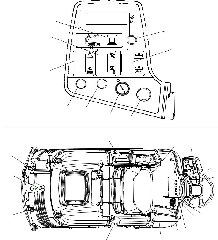
CONTROLS
3


 7 5
7 5 


6
4
9 11
1
2
21
|
18 |
17 |
|
|
|
20 |
|
|
|
|
15 |
19 |
|
8 |
|
|
20 |
|
16 |
|
13 |
|
|
|
|
|
|
10 |
|
14 |
12 |
|
|
|
|
21 |
|
3-5 |
86037580 GLIDE 01/03/07 |
|
|
|
CONTROLS
1.Key switch
2.Emergency stop button
3.One touch switch
4.Brush pressure switch
5.Solution control switch
6.Vacuum/squeegee switch
7.Display toggle switch
•Information Screen 1
•Information Screen 2
•Hour meter
•Fault codes and special icons
•Battery meter
8.Scrub Deck Shift Switch (36in only)
9.Recycle switch (optional)
10.Recycle indicator light (optional)
11.Headlight switch (optional)
12.Brake pedal
13.Parking brake lever
14.Directional control pedal and speed reduction feature.
15.Steering wheel
16.Steering tilt lever
17.Horn button
18.Seat adjustment grab bar
19.Squeegee camber adjustment knob
20.Squeegee deflection adjustment knob
21.Side squeegee deflection adjustment knob
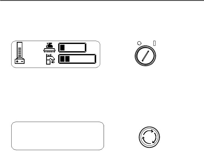
1.KEY SWITCH
Controls the power for the machine functions. To turn the machine power on, rotate key clockwise. When the key is turned on the battery symbol will flash for 12 seconds while the system runs self-diagnostics and returns scrub deck and squeegee to raised position, if necessary. The controller will not respond to other commands until this routine is complete. To turn the machine power off, rotate key counterclockwise.
INFORMATION DISPLAY
2.EMERGENCY STOP BUTTON
This safety feature is designed to cut all power to the machine at any time. To shut the machine power off, push the Emergency Stop switch. To reset the machine, rotate the switch clockwise.
INFORMATION DISPLAY
86037580 GLIDE 01/03/07 |
3-6 |
|
 Loading...