


F145-1328/F145-1378
Indoor Remote Sensor/Outdoor Remote Sensor
INSTALLATION INSTRUCTIONS
Operator: Save these instructions for future use!
FAILURE TO READ AND FOLLOW ALL INSTRUCTIONS CAREFULLY BEFORE INSTALLING OR OPERATING THIS CONTROL COULD CAUSE PERSONAL INJURY AND/OR PROPERTY DAMAGE.
INDOOR REMOTE SENSOR |
OUTDOOR REMOTE SENSOR |
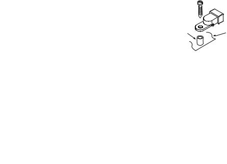
Outdoor Probe
Interior Mounting Base
NOTE
If in doubt about whether your wiring is millivolt, line, or low voltage, have it inspected by a qualified heating and air conditioning contractor or electrician.
Do not exceed the specification ratings.
All wiring must conform to local and national electrical codes and ordinances.
This control is a precision instrument, and should be handled carefully. Rough handling or distorting components could cause the control to malfunction.
The remote sensors cannot be used with systems where power interruptions are part of normal system operation.
PRECAUTIONS
! CAUTION
To prevent electrical shock and/or equipment damage, disconnect electric power to system at main fuse or circuit breaker box until installation is complete.
!WARNING
Do not use on circuits exceeding specified voltage. Higher voltage will damage control and could cause shock or fire hazard.
Do not short out terminals on gas valve or primary control to test. Short or incorrect wiring will damage thermostat and could cause personal injury and/or property damage.
The F145-1328 remote sensor is approved for indoor use only.
Temperature range: 40° to 99°F
SPECIFICATIONS
Operating humidity range: 0 to 90% RH (non-condensing).
20 gauge, three-conductor shielded cable must be used for all remote sensor wiring.
The F145-1378 remote sensor is approved for outdoor use only.
Temperature range of outdoor probe: -40° to 140°F
20 gauge, three-conductor shielded cable must be used for all remote sensor wiring.
White-Rodgers is a division |
PART NO. 37-6606A |
|
of Emerson Electric Co. |
||
|
||
www.white-rodgers.com |
0440 |
|
|
INSTALLATION |
|
|
|
|
|
INDOOR SENSOR |
OUTDOOR SENSOR |
|
SELECT SENSOR LOCATION |
SELECT SENSOR LOCATION |
|
Proper location insures that the remote sensor will provide a comfortable home or building temperature. Observe the following general rules when selecting a location:
1.The remote sensor can be located a maximum of 300 feet from the thermostat.
2.Locate sensor about 5 ft. above the room floor level.
3.Install sensor on a partitioning wall, not on an outside wall.
4.Never expose sensor to direct light from lamps, sun, fireplaces or any temperature radiating equipment.
5.Avoid locations close to windows, adjoining outside walls, or doors that lead outside.
6.Avoid locations close to air registers or in the direct path of air from them.
7.Make sure there are no pipes or duct work in that part of the wall chosen for the sensor location.
8.Never locate sensor in a room that is normally warmer or cooler than the rest of the home (such as the kitchen) or building.
9.Avoid locations with poor air circulation, such as behind doors or in alcoves.
10.In the home, the living or dining room is normally a good location, provided there is no cooking range or refrigerator on opposite side of wall.
Proper location insures that the remote sensor will provide a correct outdoor temperature reading. Observe the following general rules when selecting a location:
1.The interior mounting base can be located a maximum of 300 feet from the thermostat.
2.Install the interior mounting base within 12 ft. of the intended outdoor probe location.
3.Never install the outdoor probe where it will be exposed to direct light from lamps, sun, fireplaces or any temperature radiating equipment.
4.Make sure there are no pipes or ductwork in the wall chosen for the base location.
5.Outdoor temperature measurement requires installing the probe outdoors. Good probe locations would be under a bay window or overhang, out of direct sunlight. Direct sun exposure will affect sensed temperature. Install probe with spacer to obtain a more accurate temperature.
Spacer |
Mounting |
|
Surface |
||
|
|
|
|
|
|
|
|
|
|
|
|
|
|
|
6. |
Although connected to the probe wire for outdoor tempera- |
|||||
|
|
|
|
|
|
|
|
|
|
|
|
|
|
|
|
ture sensing, the interior mounting base must be placed |
||||
|
|
|
|
|
|
|
|
|
|
|
|
|
|
|
|
indoors. Therefore, the interior mounting base must be |
||||
|
|
|
|
|
|
|
|
|
|
|
|
|
|
|
|
installed near the perimeter of the building, so that the |
||||
|
|
|
|
|
|
|
|
|
|
|
|
|
|
|
|
probe wire can be run through to the outside of the |
||||
|
|
|
|
|
|
|
|
|
|
|
|
|
|
|
|
structure and placed in the selected (shaded) location. The |
||||
|
|
|
|
|
|
|
|
|
|
|
|
|
|
|
|
outdoor probe wire is 12 feet long (and should not be cut |
||||
|
|
|
|
|
|
|
|
|
|
|
|
|
|
|
|
or spliced), so plan the placement of both the probe and |
||||
|
|
|
|
|
|
|
|
|
|
|
|
|
|
|
|
interior mounting base accordingly. Any excess wire may |
||||
|
|
|
|
|
|
|
|
|
|
|
|
|
|
|
|
be coiled or bundled. The probe should be connected to E2 |
||||
WIRING |
|
|
|
|
|
|
|
|
|
|
|
|
|
|
as shown in figure 2. |
|
|
|
|
|
|
|
|
|
|
|
|
|
|
|
|
|
|
|
|
|
|
|
|
||
|
|
|
|
|
|
|
|
|
|
|
|
|
|
Connection Cross Reference |
|
|||||
|
|
|
|
|
|
|
|
|
|
|
|
|
|
|
|
|
||||
|
|
|
|
|
|
|
|
|
|
|
|
|
|
|
|
Thermostats and Remote Sensors |
|
|||
|
|
|
! CAUTION |
|
|
|
|
|
|
|
||||||||||
|
|
|
|
|
|
|
|
|
|
|
|
|
|
|||||||
|
|
|
|
|
|
|
|
|
Old Terminal |
|
New Terminal |
|
||||||||
Do not allow the 3-conductor wire to be pinched |
|
|
(Thermostat or Remote) |
(Thermostat or Remote) |
||||||||||||||||
|
|
S1 |
|
+ |
|
|
||||||||||||||
between the sensor and the wall. |
|
|
|
|
|
|
|
|
|
|
||||||||||
|
|
|
|
|
|
|
S2 |
|
S |
|
||||||||||
Check wire connections before applying power. |
|
|
|
|
||||||||||||||||
|
` |
S3 |
|
- |
|
|
||||||||||||||
Improper connections will lead to permanent |
|
|
|
|
|
|||||||||||||||
|
|
|
Old/New Remote Terminal Designations |
|
||||||||||||||||
damage to the sensor. |
|
|
|
|
|
|
|
|
|
|
|
|
|
|||||||
20 Gauge Shielded cable must be used. Cable |
|
|
|
|
|
|
|
|||||||||||||
|
|
|
Model Number |
Terminal Designation |
||||||||||||||||
shield must be connected to "-" or S3 on the |
|
|
|
*F145-1049, *F145-1170 |
S1 |
S2 |
|
S3 |
||||||||||||
THERMOSTAT ONLY. |
|
|
|
|
|
|
|
|
|
|
|
|
F145-1328, F145-1378 |
+ |
S |
|
- |
|||
|
|
|
|
|
|
|
|
|
|
|
|
|
|
|
|
|
||||
|
|
|
|
|
|
|
|
|
|
|
|
|
|
|
|
*Models no longer available |
Sensor |
Sensor |
|
Sensor |
|
|
|
|
|
|
|
|
|
|
|
|
|
|
|
|
|
||||
|
|
|
|
|
|
|
|
|
|
|
|
|
|
|
|
|
Positive |
Return Signal |
|
Negative |
INDOOR SENSORS |
|
|
|
|
|
|
|
|
|
|
|
|
|
|
|
|
|
|||
|
|
|
|
|
|
|
|
|
|
|
|
|
|
|
|
|
||||
Model Number |
|
Color |
|
Dimensions |
|
|
|
|
|
|
Application |
|
|
|
|
|||||
F145-1328 |
|
Classic White |
1 |
8 |
1 |
2 |
" x |
3 |
4 |
|
Compatible with all White-Rodgers Thermostats with Indoor Remote Sense |
|||||||||
|
2 / |
" x 3 / |
|
/ " |
|
|||||||||||||||
1. 1F93-380, 1F95-371, 1F95-377 and 1F95-391 thermostats average or weight sensor priority in multiple remote applications.
OUTDOOR SENSORS
Model Number |
Color |
|
Dimensions |
|
|
Application |
||||
F145-1378 |
Classic White |
1 |
8 |
1 |
2 |
" x |
3 |
4 |
" |
Compatible with all White-Rodgers Thermostats with Outdoor Remote Sense |
2 / |
" x 3 / |
|
/ |
|||||||
|
|
with 12 ft. sensor lead |
|
|||||||
1. Outdoor Sensor provides outdoor temperature to thermostat display. Not used for averaging or cycle rate calculations except on 1F95-391.
2
 Loading...