


90 Series Blue Universal Thermostat with Automatic Heat/Cool Changeover Option
Save these instructions for future use!
FAILURE TO READ AND FOLLOW ALL INSTRUCTIONS CAREFULLY BEFORE INSTALLING OR OPERATING THIS CONTROL COULD CAUSE PERSONAL INJURY AND/OR PROPERTY DAMAGE.
Single Stage, Multi-Stage, Heat Pump Installation and Operating Instructions for Model:
Model |
Programming Choices |
||
|
|
|
|
1F95-1277 |
Non-Programmable |
5/1/1 Day |
7 Day |
|
|
|
|
APPLICATIONS
THERMOSTAT APPLICATION GUIDE
Description |
|
1F95-1277 Touchscreen Thermostat |
|
|
|
Heat Pump (No Aux. or Emergency Heat) |
Yes |
|
Heat Pump (with Aux. or Emergency Heat) |
Yes |
|
Systems with up to 3 Stages Heat, 2 Stages Cool |
Yes |
|
Heat Only Systems |
Yes |
|
Millivolt Heat Only Systems – Floor or Wall Furnaces |
Yes |
|
Cool Only Systems |
Yes |
|
Gas or Oil Heat |
Yes |
|
Electric Furnace |
Yes |
|
Hydronic (Hot Water) Zone Heat – 2 Wires |
Yes |
|
Hydronic (Hot Water) Zone Heat – 3 Wires |
Yes |
|
Wired Remote Temperature Sensor (Indoor/Outdoor) |
Yes |
|
Dual Fuel Feature (Heat Pump Mode) |
Yes |
|
|
|
|
SPECIFICATIONS
Electrical Rating: |
|
Battery Power . . . . . . . . . . . . . . . . . . . . . . . . . |
mV to 30 VAC, NEC Class II, 50/60 Hz or DC |
Input-Hardwire . . . . . . . . . . . . . . . . . . . . . . . . |
20 to 30 VAC |
Terminal Load . . . . . . . . . . . . . . . . . . . . . . . . . . . . |
1.5A per terminal, 2.5A maximum all terminals combined |
Setpoint Range . . . . . . . . . . . . . . . . . . . . . . . . . . . |
45 to 99°F (7 to 32°C) |
Differential (Single Stage) . . . . . . . . . . . . . . . . . . . |
Heat 0.6°F; Cool 1.2°F |
Differential (Multi-Stage) . . . . . . . . . . . . . . . . . . . . |
Heat 0.6°F; Cool 1.2°F |
Differential (Heat Pump) . . . . . . . . . . . . . . . . . . . . |
Heat 1.2°F; Cool 1.5°F |
Operating Ambient . . . . . . . . . . . . . . . . . . . . . . . . . |
32°F to +105°F (0 to +41°C) |
Operating Humidity . . . . . . . . . . . . . . . . . . . . . . . . |
90% non-condensing max. |
Shipping Temperature Range . . . . . . . . . . . . . . . . |
-4 to +150°F (-20 to +65°C) |
Dimensions Thermostat . . . . . . . . . . . . . . . . . . . . . |
4.6"H x 5.9"W x 1.2"D |
|
|
! CAUTION
To prevent electrical shock and/or equipment damage, disconnect electric power to system at main fuse or circuit breaker box until installation is complete.
Index |
Page |
|
|
Installation |
2 |
Wiring Connections |
2 |
Thermostat Quick Reference |
3 |
Installer Configuration Menu |
4 |
Operating Your Thermostat |
7 |
Programming |
7 |
Troubleshooting |
11 |
ATTENTION: MERCURY NOTICE
This product does not contain mercury. However, this product may replace a product that contains mercury.
Mercury and products containing mercury must not be discarded in household trash. Do not touch any spilled mercury. Wearing non-absorbent gloves, clean up any spilled mercury and place in a sealed container. For proper disposal of a product containing mercury or a sealed container of spilled mercury, place it in a suitable shipping container and send it to:
White-Rodgers
2895 Harrison Street
Batesville, AR 72501
PART NO. 37-6753A
www.white-rodgers.com
0626
INSTALLATION
!WARNING
Thermostat installation and all components of the control system shall conform to Class II circuits per the NEC code.
Remove Old Thermostat
A standard heat/cool thermostat consists of three basic parts:
1.The cover, which may be either a snap-on or hinge type.
2.The base, which is removed by loosening all captive screws.
3.The switching subbase, which is removed by unscrewing the mounting screws that hold it on the wall or adapter plate. Before removing wires from old thermostat, label each wire with the terminal designation from which it was attached. Disconnect the wires from the old thermostat one at a time. Do not let wires fall back into the wall.
Installing New Thermostat
1.Pull the thermostat body off the thermostat base. Forcing or prying on the thermostat will cause damage to the unit.
2.Place base over hole in wall and mark mounting hole locations on wall using base as a template.
3.Move base out of the way. Drill mounting holes. If you are using existing mounting holes and the holes drilled are too large and do not allow you to tighten base snugly, use plastic screw anchors to secure the base.
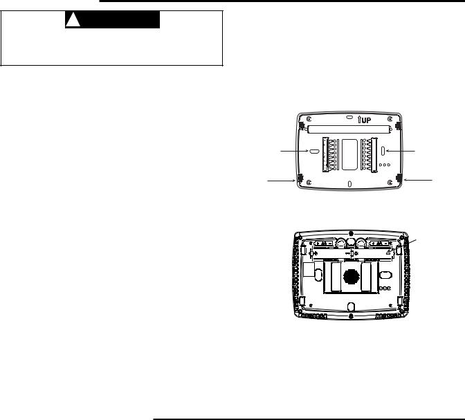
4.Fasten base snugly to wall using mounting holes shown in Figure 1 and two mounting screws. Leveling is for appearance only and will not affect thermostat operation.
5.Connect wires to terminal block on base using appropriate wiring schematic (see diagram sheet 37-6808A).
6.Push excess wire into wall and plug hole with a fire resistant material (such as fiberglass insulation) to prevent drafts from affecting thermostat operation.
7.Carefully line the thermostat up with the base and snap into place.
Battery Location
2 "AA" alkaline batteries are included in the thermostat at the factory with a battery tag to prevent power drainage. Remove the battery tag to engage the batteries.
To replace batteries, set system to OFF, remove thermostat from wall and install the batteries in the rear along the top of the thermostat (see Figure 1).
Figure 1 – Thermostat Base Multi-Stage 1F95-1277
Mounting |
|
+ |
Mounting |
|
S |
||
Hole |
Y2 |
- |
Hole |
|
W2 |
||
|
|
|
|
|
|
W/E |
|
|
|
6 |
|
Place Level |
|
L |
Place Level |
|
|
||
across |
|
|
across |
Mounting Tabs |
|
|
Mounting Tabs |
(for appearance only) |
|
|
(for appearance only) |
Rear view of thermostat
2 "AA" Batteries
WIRING CONNECTIONS
Refer to equipment manufacturers' instructions for specific |
For wiring diagrams, see 37-6808A. |
system wiring information. After wiring, see CONFIGURA- |
Wiring diagrams shown are for typical systems and describe |
TION section for proper thermostat configuration. |
the thermostat terminal functions. |
TERMINAL DESIGNATION DESCRIPTIONS
Terminal Designation |
Description |
B . . . . . . . . . . . . . . . . . . |
Changeover valve for heat pump energized constantly in heating |
O . . . . . . . . . . . . . . . . . . |
Changeover valve for heat pump energized constantly in cooling |
Y2 . . . . . . . . . . . . . . . . . . |
2nd Stage Compressor |
Y . . . . . . . . . . . . . . . . . . |
Compressor Relay |
G . . . . . . . . . . . . . . . . . . |
Fan Relay |
RC . . . . . . . . . . . . . . . . . . |
Power for Cooling |
RH . . . . . . . . . . . . . . . . . . |
Power for Heating |
C . . . . . . . . . . . . . . . . . . |
Common wire from secondary side of cooling |
L . . . . . . . . . . . . . . . . . . |
Heat pump malfunction indicator for systems with malfunction connection |
6 . . . . . . . . . . . . . . . . . . |
Powered closed 3rd wire for 3-wire zone valve |
W/E . . . . . . . . . . . . . . . . . |
Heat Relay/Emergency Heat Relay (Stage 1) |
W2 . . . . . . . . . . . . . . . . . . |
2nd Stage Heat (3rd Stage Heat in HP2) |
Blank . . . . . . . . . . . . . . . . . |
Blank |
- . . . . . . . . . . . . . . . . . . . |
Common (DC) for wired remote temperature sensor |
S . . . . . . . . . . . . . . . . . . |
Frequency signal from remote temperature sensor |
+ . . . . . . . . . . . . . . . . . . |
Power (DC) to remote temperature sensor |
|
|
2

THERMOSTAT QUICK REFERENCE
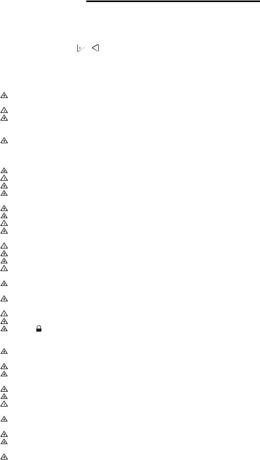
Home Screen Description
Time of Day
System
Switch
Fan
Switch
Figure 2 – Home Screen Display
Day of Week
Indicates when thermostat is calling for Heat or Cool
Programming and Configuration Items
1 Displays |
and "Keypad Lockout" when in keypad |
lockout mode. |
|
Displays |
and "Temperature Limit" and "Keypad |
Lockout" when limited range is activated and locked. Displays only "Temperature Limit" when limited range is activated.
2Indicates period of day being programmed.
3RUN SCHEDULE (run program) button.
4 SET TIME button or HOLD temperature button.
5Displays "Change Filter" when the system has run for the programmed filter time period as a reminder to change or clean your filter.
6COPY button or INSTALLER CONFIG button.
7CLEAN DISPLAY button allows 30 seconds to wipe off the display or ADVANCE DAY button for programming.
8Used in programming to set time and in configuration menu to change selections.
9"Hold Until" indicates the time when a temporary hold period will end.
10"Hours" and "Days" displays during steps in installer configuration.
11The words "Hold At" are displayed when the thermostat is in the HOLD mode. "Temporary Hold At" is displayed when the thermostat is in a temporary HOLD mode.
12"Call For Service" indicates a fault in the heating/ cooling system. It does not indicate a fault in the thermostat.
16 |
10 |
|
11 |
|
9 |
|
|
|
|
8 |
|
|
|
1 |
|
|
|
|
|
|
14 |
13 |
15 |
2 |
|
|
|
|
12 |
|
|
|
|
3 |
|
7 |
6 |
5 |
4 |
13"System On" indicates when heating or cooling stage is energized. "+2" also indicates when a second stage is energized.
14"Copy" indicates the copy program feature is being used during programming.
15A steady "Cool Savings" display indicates the feature is enabled in the installer menu. A flashing "Cool Savings" display indicates the feature is active.
16"Remote" indicates that the indoor remote temperature sensor, is being accessed. "Outdoor Remote" indicates the outdoor remote temperature sensor is being accessed.
3
INSTALLER/CONFIGURATION MENU
To enter the menu: Press the Menu touch key. Press and hold for 5 seconds the Installer Config touch key. This displays menu item #1 in the table below. Press  to advance to the next menu item or
  to return to a previous menu item. Press
  or
or  to change a menu item.
|
|
|
|
|
CONFIGURATION MENU |
||||
Menu |
|
Non- |
|
Displayed |
Press |
or |
|
|
|
|
|
|
|||||||
Reference |
Program- |
Program- |
Press |
(Factory |
to select from |
|
|||
Number |
mable |
mable |
Button |
Default) |
listed options |
Comments |
|||
|
|
|
|
|
|
|
|||
1 |
1 |
1 |
|
MS 2 |
HP 1, HP 2, SS 1 |
Selects Multi-Stage (MS 2, No Heat Pump), Heat Pump 1 |
|||
|
|
|
|
|
|
|
|
|
(HP 1, 1 compressor), Heat Pump 2 (HP 2, 2 compressor |
|
|
|
|
|
|
|
|
|
or 2 speed compressor), or Single Stage. |
2 |
2 |
2 |
|
(ELE) |
GAS |
|
|
|
GAS setting: furnace controls blower. |
|
|
|
|
|
|
|
|
|
ELE setting: thermostat controls blower. |
3 |
3 |
3 |
|
Days, (7) P |
5-1-1 or 0 |
Programs per week. (0 = non-programmable) |
|||
4 |
4 |
NA |
|
PS (4) |
2 |
|
|
|
Program periods per day. |
|
|
|
|
|
|
|
|
|
4 = Morning, Day, Evening, Night |
|
|
|
|
|
|
|
|
|
2 = Day, Night |
5 |
5 |
4 |
|
Cool-Off- |
Cool-Off-Heat, |
System switch configuration in non heat pump mode. |
|||
|
|
|
|
Heat-Auto |
Off-Heat, Cool-Off |
|
|||
|
|
|
|
Cool-Off-Heat- |
Cool-Off-Heat-Emer, |
System switch configuration, heat pump mode. |
|||
|
|
|
|
Emer-Auto |
Off-Heat-Emer, Cool-Off |
|
|||
6 |
6 |
NA |
|
E (On) |
OFF |
|
|
|
Selects Energy Management Recovery, E (with programming option on) |
7 |
7 |
5 |
|
Cr, Heat (FA) |
SL |
|
|
|
Selects Adjustable Anticipation, cycle rate, Heat |
8 |
8 |
6 |
|
Cr, Cool (FA) |
SL |
|
|
|
Selects Adjustable Anticipation, cycle rate, Cool |
9 |
9 |
7 |
|
Cr/AU, Emer (FA) |
SL |
|
|
|
Selects Adjustable Anticipation, cycle rate auxiliary, (This item is |
|
|
|
|
|
|
|
|
|
only to appear if HP 1 or HP 2 is selected above). |
10 |
10 |
8 |
|
CL (OFF) |
On |
|
|
|
Selects Compressor Lockout. |
11 |
11 |
9 |
|
dL (On) |
OFF |
|
|
|
Selects Continuous Display backlight & intensity. |
12 |
12 |
10 |
|
dL (LO) |
HI |
|
|
|
Selects Backlight Intensity. |
13 |
13 |
11 |
|
0 |
4, LO to 4, HI |
Selects Adjustable Ambient Temperature Display [range -4 (LO) to |
|||
|
|
|
|
|
|
|
|
|
+4 (HI)]. |
14 |
14 |
12 |
|
°F |
°C |
|
|
|
Selects °F/°C Display (temperature units in Fahrenheit or Celsius). |
15 |
15 |
13 |
|
b (On) |
OFF |
|
|
|
Selects audible Beeper On/Off. |
16 |
16 |
14 |
|
dS (On) |
OFF |
|
|
|
Selects Daylight Saving Time calculation. |
17 |
17 |
15 |
|
AS, Heat (On) |
OFF |
|
|
|
Selects Automatic Schedule for comfort temperature Programming, |
|
|
|
|
|
|
|
|
|
heat mode. |
18 |
18 |
16 |
|
AS, Cool (On) |
OFF |
|
|
|
Selects Automatic Schedule for comfort temperature Programming, |
|
|
|
|
|
|
|
|
|
cool mode. |
|
|
|
|
|
|
|
|
|
|
19 |
19 |
17 |
|
CS, (OFF) |
1-2-3-4-5-6 |
|
|
Selects Cool Saving Feature & amount. |
|
|
|
|
|
Cool Savings |
|
|
|
|
|
|
|
|
|
|
|
|
|
|
|
20 |
20 |
18 |
|
HL, Heat (99) |
62-98 |
|
|
|
TEMPERATURE LIMIT, HEAT (max. heat set point). |
21 |
21 |
19 |
|
LL, Cool (45) |
46-82 |
|
|
|
TEMPERATURE LIMIT, COOL (min. cool set point). |
22 |
22 |
20 |
|
OFF, |
L (total), P (partial), |
Selects Keypad Lockout. |
|||
|
|
|
|
Keypad Lockout |
Temperature Limit |
|
|||
|
|
|
|
|
(limited temperature range) |
|
|||
|
|
|
|
000 |
001-999 |
|
|
Selects Keypad Lockout Combination (active only if keypad Lockout |
|
|
|
|
|
|
|
|
|
|
is selected). |
23 |
23 |
21 |
|
FS, Heat (On) |
OFF |
|
|
|
Fast second stage of heat (not available if SS1 is selected above). |
24 |
24 |
22 |
|
FS, Cool (On) |
OFF |
|
|
|
Fast second stage of cool (not available if SS1 or HP1 is selected |
|
|
|
|
|
|
|
|
|
above). |
25 |
25 |
23 |
|
Remote (OFF) |
On |
|
|
|
Remote temperature sensor, enable/disable. |
|
|
|
|
In, Remote |
Outdoor Remote |
Remote temperature sensor (Indoor/Outdoor). |
|||
|
|
|
|
|
|
|
|
|
|
|
|
|
|
LS (On) |
OFF |
|
|
|
Local temp. Sensor enable/disable (only when Indoor Remote is |
|
|
|
|
|
|
|
|
|
selected On). |
26 |
26 |
24 |
|
dF (5) |
5-50 |
|
|
|
Selects Dual Fuel Feature & set point (in Fahrenheit) (applicable only |
|
|
|
|
|
|
|
|
|
when HP1 or HP2 is selected). |
|
|
|
|
Cd (60) |
0-99 |
|
|
|
Selects Compressor delay in seconds (only when dF is selected >5). |
27 |
27 |
25 |
|
Change Filter |
On |
|
|
|
Selects Change filter feature |
|
|
|
|
(OFF) |
|
|
|
|
|
|
|
|
|
200 Hours |
25-1975 (in increments |
Change filter, duration hours. |
|||
|
|
|
|
|
of 25 hours) |
|
|||
4
 Loading...