


Save these instructions for future use!
FAILURE TO READ AND FOLLOW ALL INSTRUCTIONS CAREFULLY BEFORE INSTALLING OR OPERATING THIS CONTROL COULD CAUSE PERSONAL INJURY AND/OR PROPERTY DAMAGE.
Blue 2” Heat Pump Thermostat
Heat Pump Installation and Operating Instructions
Model |
Programming Choices |
|
|
1F89-0211 |
Non-Programmable |
|
|
APPLICATIONS
THERMOSTAT APPLICATION GUIDE |
1F89-0211 Thermostat |
||
|
|
|
|
Thermostat |
Thermostat |
Maximum |
|
Configuration |
Applications |
Stages |
|
Options |
|
Heat/Cool |
|
|
|
|
|
Heat Pump |
Single Stage Compressor |
2/1 |
|
Single Stage |
Heat Pump Systems – 1 |
|
|
Compressor |
Stage Aux/Emergency Heat |
|
|
|
|
|
|
SPECIFICATIONS
Electrical Rating: |
|
Battery Power or Hardwire.............................. |
20 to 30 VAC, 50/60 Hz |
Terminal Load......................................................... |
1.5 A per terminal, 2.5A maximum all terminals combined |
Setpoint Range...................................................... |
45° to 90°F (7° to 32°C) |
Differential (Heat Pump)......................................... |
Heat 1.2°F; Cool 1.2°F (adjustable) |
Operating Ambient................................................. |
32° to +105°F (0° to +41°C) |
Operating Humidity................................................ |
90% non-condensing max. |
Shipping Temperature Range................................. |
-40° to +150°F (-40° to +65°C) |
Dimensions Thermostat......................................... |
3-3/4”H x 4-3/4”W x 1-1/2”D |
PRECAUTIONS
!WARNING
Do not use on circuits exceeding specified voltage. Higher voltage will damage control and could cause shock or fire hazard.
Thermostat installation and all components of the system shall conform to Class II (current limited) circuits per the NEC code. Failure to do so could cause a fire hazard.
! CAUTION
To prevent electrical shock and/or equipment damage, disconnect electric power to system at main fuse or circuit breaker box until installation is complete.
Index |
Page |
Installation |
2 |
Wiring Diagram |
3 |
Thermostat Quick Reference |
3 |
Installer Configuration Menu |
4 |
Operation |
5 |
Troubleshooting |
6 |
|
PART NO. 37-6997D |
www.white-rodgers.com |
Replaces 37-6997C |
www.emersonclimate1 .com |
1023 |
INSTALLATION
REMOVE OLD THERMOSTAT
1.Shut off electricity at the main fuse box until installation is complete. Ensure that electrical power is disconnected.
2.Remove the front cover of the old thermostat. With wires still attached, remove wall plate from the wall. If the old thermostat has a wall mounting plate, remove the thermostat and the wall mounting plate as an assembly.
3.Identify each wire attached to the old thermostat using the labels enclosed with the new thermostat.
4.Disconnect the wires from old thermostat one at a time. DO
NOT LET WIRES FALL BACK INTO THE WALL.
5.Install new thermostat using the following procedures.
ATTENTION!
This product does not contain mercury. However, this product may replace a unit which contains mercury.
Do not open mercury cells. If a cell becomes damaged, do not touch any spilled mercury. Wearing nonabsorbent gloves, take up the spilled mercury and place into a container which can be sealed. If a cell becomes damaged, the unit should be discarded.
Mercury must not be discarded in household trash. When the unit this product is replacing is to be discarded, place in a suitable container. Refer to www.white-rodgers.com for location to send the product containing mercury.
ATTACH THERMOSTAT BASE TO WALL
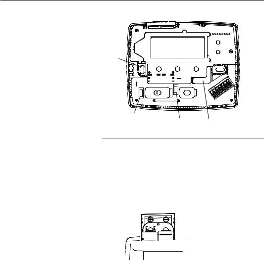
1.Remove the packing material from the thermostat. Gently pull the cover straight off the base. Forcing or prying on the thermostat will cause damage to the unit.
2.Place base over hole in wall and mark mounting hole locations on wall using base as a template (see Fig.1).
3.Move base out of the way. Drill mounting holes.
4.Push wires through opening in thermostat base.
5.Fasten base loosely to wall using two mounting screws. Place a level against bottom of base, adjust until level, and then tighten screws. (Leveling is for appearance only and will not affect thermostat operation.) If you are using existing mounting holes, or if holes drilled are too large and do not allow you to tighten base snugly, use plastic screw anchors to secure subbase.
6.Connect wires to terminals on base using appropriate wiring schematic (see figs. 2 through 4).
7.Push excess wire into wall and plug hole with a fire-resistant material (such as fiberglass insulation) to prevent drafts from affecting thermostat operation.
O/B TERMINAL SWITCH SELECTION
The O/B switch on this thermostat is factory set to the “O” position. This will accommodate the majority of heat pump applications, which require the changeover relay to be energized in COOL. If the thermostat you are replacing or the heat pump being installed with this thermostat requires a “B” terminal, to energize the changeover relay in HEAT, the O/B switch must be moved to the “B” position.
Battery
 Door
Door
Mounting
Hole
Mounting
 Hole
Hole
FAN |
|
|
(Ele/Gas) |
O/B |
Opening |
Switch |
Switch |
for wires |
Figure 1. Thermostat Base
FAN (ELE/GAS) SWITCH
For Electric Heat, heat pump or any system that requires the thermostat to turn on the blower on a call for heat– place the FAN (Ele/Gas) switch (Fig. 1) in the ON position. For Auxiliary and Emergency Heat systems that have a fan control to turn on the blower (independent of the thermostat) place switch in the OFF position.
BATTERY LOCATION
 “AA” Alkaline Batteries
Two “AA” alkaline batteries are installed in your thermostat with a battery tag to prevent power drainage. Prior to use, open the battery door and remove the battery tag. To open, pull the battery door as shown by the arrow and lift open. The two “AA” batteries will operate all functions or maintain time and continuously display the temperature during a loss of AC power. Installed batteries will also allow programming prior to installation. To replace batteries, pull the battery door shown by the arrow and lift open. Using the polarity indicated inside the battery door, insert the batteries. To close the battery door, swing the door down while pulling in the direction of arrow. Once fully down, snap the door back into position.
Thermostat can be powered by system AC power or Battery. If  is displayed, the thermostat is battery powered.If
 is not displayed, thermostat is system powered with optional battery back-up. When battery power remaining is approximately half, the
  will be displayed. When “Change
  ” is displayed, install fresh “AA” alkaline batteries immediately. For best results, use new premium brand alkaline batteries such as Duracell® or Energizer®. We recommend replacing batteries every 2 years. If the home is going to be unoccupied for an extended period (over 3 months) and
  is displayed, the batteries should be replaced before leaving. When less than two months of battery life remain, the setpoint temperature will offset by 10 degrees (10 degrees cooler in Heat mode / 10 degrees warmer in Cool mode). If offset occurs, the normal setpoint can be manually reset with
  or
or  . Another offset will occur within two days if batteries are not replaced. To
replace the batteries, set system to OFF.
2
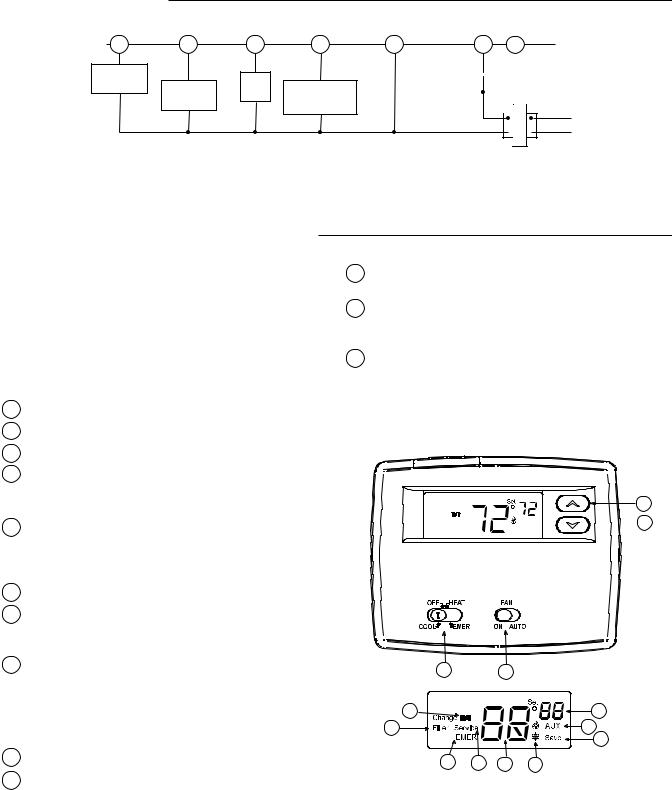
WIRING DIAGRAM
O/B |
Y |
G |
W2 |
C ** |
Changeover |
|
Fan |
|
|
Relay* |
Compressor |
Aux/Emergency |
|
|
Relay |
|
|||
|
Contactor |
Heat Relay |
|
|
|
|
|
||
|
|
(Stage 2) |
|
|
|
|
|
|
*Changeover Relay is energized in COOL when O/B switch is in the “O” position Changeover Relay is energized in HEAT when O/B switch is in the “B” position
**The 24 volt neutral connection to terminal C on the thermostat is not required if you replace the batteries once a year with fresh “AA” alkaline batteries.
THERMOSTAT
|
L |
R |
|||||
SYSTEM |
|
|
|
SYSTEM |
|||
|
|
|
|||||
|
|
|
|
||||
MONITOR |
|
|
|
|
|
|
|
|
|
|
|
|
|||
SWITCH |
|
|
|
|
|||
|
|
|
|
|
|
|
Hot |
24 VAC |
|
|
|
||||
|
|
|
|||||
|
|
||||||
|
|
|
120 VAC |
||||
Neutral
TRANSFORMER
(Class II Current Limited)
Figure 2. Typical wiring diagram for single transformer systems
THERMOSTAT QUICK REFERENCE
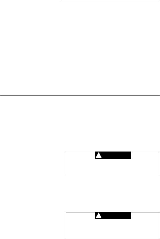
Before you begin programming your thermostat, you should be familiar with its features and with the display and the location and operation of the thermostat buttons and switches (see fig. 3). Your thermostat consists of two parts: the thermostat cover and the base. To remove the cover, pull it straight out from the base. To replace the cover, line up the cover with the base and press until the cover snaps onto the base.
The Thermostat Buttons and Switches
1Raises temperature setting.
2Lowers temperature setting.
3SYSTEM switch (COOL, OFF, HEAT, EMER).
4FAN switch (ON, AUTO).
The Display
5Indicates setpoint temperature.This is blank when system switch is in the OFF position. Setpoint temperature is displayed (flashing) if the thermostat is in lockout mode to prevent the compressor from cycling too quickly.
6“AUX” indicates auxiliary stage is operating.
7“Save” indicates the Cool Savings feature is enabled in the configuration menu. “Save” (flashing) indicates Cool Savings feature is active.
8Flame icon ( ) is displayed when the SYSTEM switch is in the HEAT position. Flame icon (
 ) is displayed flashing when thermostat is calling for heat. Snowflake icon (
 ) is displayed (non-flashing) when the SYSTEM switch is in the COOL position. Snowflake icon (
 ) is displayed (flashing) if the thermostat is calling for cool.
9Displays current temperature.
10“Service” indicates a diagnostic fault in the heating/ cooling system. It does not indicate a fault in the thermostat.
11“EMER” is displayed flashing when the system switch is in EMER position.
12“Change Filter” is displayed when the system has run for the programmed filter time period as a reminder to change or clean your air filter.
13“ ” indicates when batteries are low and should be replaced.
Figure 3. Thermostat display, buttons and switches
1
 2
2
3 |
|
4 |
|
13 |
|
|
5 |
12 |
|
|
6 |
|
|
|
7 |
11 |
10 |
9 |
8 |
3

INSTALLER/CONFIGURATION MENU
The configuration menu allows you to set certain thermostat operating characteristics to your system or personal requirements. To enter the menu: Set your thermostat switch to OFF. Press and hold the  and
and  buttons simultaneously for approximately 5 seconds. The display will change to show the first item in the configuration menu. Press the
  or
or  button to change the setting. Press the
  and
and  buttons simultaneously again to change to the next menu item. Continue through all steps to accept your new settings. To exit the menu set the system switch to COOL, HEAT or EMER. If no keys are pressed within fifteen minutes, the thermostat will revert to normal operation.
1)Select CS (Cool Savings™) - With Cool Savings™ enabled, the thermostat will make small adjustments to the Setpoint temperature during periods of high demand to reduce cooling system running time and save energy. When the cooling system has been running for more than 20 minutes, humidity in the home will be lower and a higher setpoint temperature will feel comfortable. After 20 minutes of run time, the thermostat will start increasing the setpoint temperature in steps of less than one degree as the system continues to run. These adjustments will eventually cause the system to satisfy the thermostat and turn the system off to reduce the energy consumption. When the Cool Savings feature is active and making adjustments, the display will show “Save”.The amount of the adjustments to the setpoint temperature is dependent on the Cool Savings value that
is set, 1 being the least adjustment and 6 being the most adjustment. With this feature set to OFF, no change will occur when the cooling system is continuously running during the periods of high demand. Periods of high demand will normally occur during the late afternoon and early evening on the hottest days of the summer.
2 & 3) Select Cycle Rate Selection - The factory default setting is (FA, CR) for all modes (Heat Pump, Heat Pump Aux, Heat and Cool). To change to slow cycling (SL, CR), press the 
 or
or  keys to toggle between FA & SL.
The cycle rate differentials for different settings are:
MODE |
Fast |
Slow |
|
FA |
SL |
Heat Pump |
1.2°F |
1.7°F |
HP Aux |
0.8°F |
1.2°F |
4)Select Compressor Lockout CL OFF or ON - Selecting CL On will cause the thermostat to wait 5 minutes between cooling cycles. This is intended to help protect the compressor from short cycling. Some newer compressors already have a time delay built in and do not require this feature. Your compressor manufacturer can tell you if the lockout feature is already present in their system. When the thermostat compressor time delay occurs, it will flash the setpoint for up to five minutes.
Configuration Menu
Menu |
Press |
Displayed |
Press |
or |
Comments |
Reference |
Key |
(Factory |
to select |
|
|
Number |
|
Default) |
from listed |
|
|
|
|
|
options |
|
|
1 |
and |
CS |
On |
|
Select Cool Savings Feature On or OFF |
|
|
(OFF) |
|
|
|
|
and |
CS |
1, 2, 3, 4, 5, 6 |
If CS selected On, selects Cool Savings value |
|
|
|
(3) |
|
|
|
2 |
and |
CR HE-PU |
SL |
|
Select Adjustable Anticipation, cycle rate, Heat |
|
|
(FA) |
|
|
Pump, Heat and Cool |
3 |
and |
CR Aux |
SL |
|
Select Adjustable Anticipation, cycle rate, |
|
|
(FA) |
|
|
Heat Pump Aux Stage |
4 |
and |
CL |
On |
|
Select Compressor lockout OFF or On |
|
|
(OFF) |
|
|
|
5 |
and |
L |
OFF |
|
Select Display Light On or OFF |
|
|
(On) |
|
|
|
6 |
and |
Temp |
4 LO to |
|
Select temperature display adjustment higher |
|
|
(0 HI) |
4 HI |
|
or lower |
7 |
and |
oF |
oC |
|
Select oF / oC Display (temperature units in |
|
|
|
|
|
Fahrenheit or Celsius) |
8 |
and |
FH |
OFF |
|
Select fast second stage On or OFF |
|
|
(On) |
|
|
|
9 |
and |
Change Filter |
On |
|
Select filter replacement indicator OFF or On |
|
|
(OFF) |
|
|
|
|
and |
Change Filter |
25 to 1975 |
If Change Filter selected On, selects time inter- |
|
|
|
(200 h) |
|
|
val for Change Filter Indicator. |
|
|
|
|
|
(in 25 hour increments) |
10 |
and |
|
|
|
Returns to normal operation |
4
INSTALLER/CONFIGURATION MENU
5)Select Backlight Display - The display backlight improves display contrast in low lighting conditions. When the “C” terminal is connected, selecting backlight CdL On will keep the light on continuously. Select backlight OFF will turn the light on momentarily when any key is pressed. When the “C” terminal is not connected, regardless of the backlight selection, the light will be on momentarily when any key is pressed.
6)Select Temperature Display Adjustment 4 LO to 4 HI -
Allows you to adjust the room temperature display up to 4° higher or lower. Your thermostat was accurately calibrated at the factory but you have the option to change the display temperature to match your previous thermostat. The current or adjusted room temperature will be displayed on the display.
7)Select F° or C° Readout - Changes the display readout to Celsius or Fahrenheit as required.
8)Select Fast Second Stage ON or OFF - (Heat Pump Only) In the HEAT mode, with the Fast Heat feature enabled (FH Heat On), if the temperature is manually raised by 3°F (2°C) or more above the actual temperature using the  , the second stage will energize immediately. With FH OFF, the thermostat will determine the optimum time (approximately 0 to 30 minutes) to use Auxiliary/Second stage heat in addition to the Heat Pump.
9)Select Filter Replacement Reminder and Set Run Time
Select the “Change Filter” reminder On or OFF. If selected On, press  and
and  to select the time period from 25 to 1975 hours in 25 hour increments. In a typical application, 200 hours (default) of run time is approximately 30 days. After the selected time of blower operation, the thermostat will display “Change Filter” as a reminder to change or clean your air filter. When “Change Filter” is displayed, press the
  and
and  button to clear the display and restart the time to the next filter change. A selection of OFF will cancel this feature.
OPERATION
CHECK THERMOSTAT OPERATION
If at any time during testing your system does not operate properly, contact a qualified service person.
Turn on power to the system.
Fan Operation
If your system does not have a G terminal connection, skip to
Heating System.
1.Move fan switch to ON position. The blower should begin to operate.
2.Move fan switch to AUTO position. The blower should stop immediately.
Heating System
1.Move SYSTEM switch to HEAT position. If the auxiliary heating system has a standing pilot, be sure to light it.
2.Press  to adjust thermostat setting to 1° above room temperature. The Flame icon (
 ) will begin to flash and the Heat Pump system should begin to operate. However, if the setpoint temperature is flashing, the compressor lockout feature is operating (see Configuration menu, item 6).
3.Adjust temperature setting to 4o above room temperature. The auxiliary heat system should begin to operate and the Aux icon will be flashing.
4.Press  to adjust temperature setting below room temperature. The heating system should stop operating.
Emergency System
EMER bypasses the Heat Pump to use the heat source wired to terminal W2 on the thermostat. EMER is typically used when compressor operation is not desired, or you prefer back-up heat only.
1.Move SYSTEM switch to EMER position, EMER will flash on the display.
2.Press  to adjust the thermostat above room temperature. The Aux heating system will begin to operate. The Flame icon (
 ) will display flashing to indicate that the Aux system is operating.
3.Press  to adjust the thermostat below room temperature. The Aux heating system should stop operating.
Cooling System
! CAUTION
To prevent compressor and/or property damage, if the outdoor temperature is below 50oF, DO NOT operate the cooling system.
1.Move SYSTEM switch to COOL position.
2.Press  to adjust thermostat setting below room temperature. The blower should come on immediately on high speed, followed by cold air circulation.
3.Press  to adjust temperature setting above room temperature. The cooling system should stop operating.
! CAUTION
Do not allow the compressor to run unless the compressor oil heaters have been operational for 6 hours and the system has not been operational for at least 5 minutes.
5
 Loading...