


Save these instructions for future use!
FAILURE TO READ AND FOLLOW ALL INSTRUCTIONS CAREFULLY BEFORE INSTALLING OR OPERATING THIS CONTROL COULD CAUSE PERSONAL INJURY AND/OR PROPERTY DAMAGE.
Blue Universal Thermostat with Automatic Heat/Cool Changeover Option
Single Stage, Multi-Stage or Heat Pump Installation and Operating Instructions for Models:
Model |
Programming Choices |
||
|
|
|
|
1F85-0422 |
5+1+1 Day |
5+2 Day |
Non-Programmable |
|
|
|
|
1F83-0422 |
|
Non-Programmable |
|
|
|
|
|
|
|
|
APPLICATIONS |
THERMOSTAT APPLICATION GUIDE |
|
|
|
|
1F83-0422 Thermostat |
||
|
|
|
|
Description |
|
|
|
Heat Pump (No Aux. or Emergency Heat) |
Yes |
|
|
Heat Pump (with Aux. or Emergency Heat) |
Yes |
|
|
Systems with up to 2 Stages Heat, 2 Stages Cool |
Yes |
|
|
Heat Only Systems (with optional fan switch) |
Yes |
|
|
Millivolt Heat Only Systems – Floor or Wall Furnaces |
Yes |
|
|
Cool Only Systems |
Yes |
|
|
Gas or Oil Heat |
Yes |
|
|
Electric Furnace |
Yes |
|
|
Hydronic (Hot Water) Zone Heat – 2 Wires |
Yes |
|
|
Hydronic (Hot Water) Zone Heat – 3 Wires |
Yes |
|
|
|
|
|
|
|
SPECIFICATIONS |
Electrical Rating: |
|
|
|
|
|
|
|
|
|
|
|
Battery Power..................................................... |
mV to 30 VAC, NEC Class II, 50/60 Hz or DC |
||||
Input-Hardwire.................................................... |
20 to 30 VAC |
|
|
||
Terminal Load............................................................ |
1.5 |
A per terminal, 2.5A maximum all terminals combined |
|||
Setpoint Range.......................................................... |
45° to 90°F (7° to 32°C) |
||||
Rated Differentials: |
Fast |
Med. |
Slow |
||
Heat (SS1, MS2)................................................ |
0.4 |
°F |
0.6 °F |
1.7 °F |
|
Cool (SS1, MS2)................................................ |
0.9 |
°F |
1.2 °F |
1.7 °F |
|
Heat Pump (HP1, HP2)...................................... |
0.9 |
°F |
1.2 °F |
1.7 °F |
|
Emer (HP1, HP2)............................................... |
0.6 |
°F |
– |
1.7 °F |
|
Operating Ambient.................................................... |
32° to +105°F (0° to +41°C) |
||||
Operating Humidity.................................................... |
90% non-condensing max. |
||||
Shipping Temperature Range.................................... |
-40° to +150°F (-40° to +65°C) |
||||
Dimensions Thermostat............................................ |
3-7/8”H x 5-1/8”W x 1-1/4”D |
||||
|
|
|
|
|
|
! CAUTION
To prevent electrical shock and/or equipment damage, disconnect electric power to system at main fuse or circuit breaker box until installation is complete.
Index |
Page |
Installation |
2 |
Wiring Connections |
2 |
Thermostat Quick Reference |
3 |
Installer Configuration Menu |
4 |
Operating Your Thermostat |
6 |
Programming |
7 |
Troubleshooting |
8 |
ATTENTION: MERCURY NOTICE
This product does not contain mercury. However, this product may replace a product that contains mercury.
Mercury and products containing mercury must not be discarded in household trash. Do not touch any spilled mercury. Wearing non-absorbent gloves, clean up any spilled mercury and place in a sealed container. For proper disposal of a product containing mercury or a sealed container of spilled mercury, place it in a suitable shipping container. Refer to www.thermostat-recycle.org for location to send product containing mercury.
|
PART NO. 37-7240B |
www.white-rodgers.com |
Replaces 37-7240A |
www.emersonclimate.com |
1316 |
INSTALLATION
!WARNING
Thermostat installation and all components of the control system shall conform to Class II circuits per the NEC code.
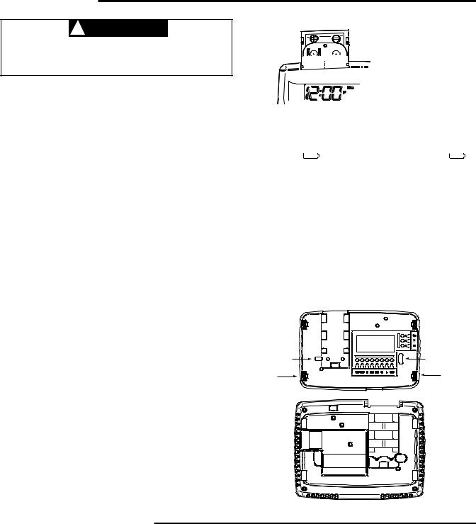
Figure 1 – Battery door shown open

 “AA” Alkaline Batteries
Remove Old Thermostat
A standard heat/cool thermostat consists of three basic parts:
1)The cover, which may be either a snap-on or hinge type.
2)The base, which is removed by loosening all captive screws.
3)The switching subbase, which is removed by unscrewing the mounting screws that hold it on the wall or adapter plate. Before removing wires from old thermostat, label each wire with the terminal designation from which it was attached. Disconnect the wires from the old thermostat one at a time. Do not let wires fall back into the wall.
Installing New Thermostat
1)Pull the thermostat body off the thermostat base. Forcing or prying on the thermostat will cause damage to the unit.
2)Place base over hole in wall and mark mounting hole locations on wall using base as a template.
3)Move base out of the way. Drill mounting holes. If you are using existing mounting holes and the holes drilled are too large and do not allow you to tighten base snugly, use plastic screw anchors to secure the base.
4)Fasten base snugly to wall using mounting holes shown in Figure 2 and two mounting screws. Leveling is for appearance only and will not affect thermostat operation.
5)Connect wires to terminal block on base.
6)Push excess wire into wall and plug hole with a fire resistant material (such as fiberglass insulation) to prevent drafts from affecting thermostat operation.
7)Carefully line the thermostat up with the base and snap into place.
Batteries
2 “AA” alkaline batteries are included with the thermostat. To install the batteries, pull the battery door as shown by the
arrow and lift open. Using the polarity indicated inside the battery door, insert the batteries. To close the battery door, swing the door down while pulling in the direction of arrow. Once fully down, snap the door back into position. To replace the batteries, set system to OFF.
Thermostat can be powered by system AC power or Battery. If is displayed, the thermostat is battery powered. If
 is not displayed, thermostat is system powered with optional battery back-up. When battery power remaining is approxi-
mately half, the |
|
|
|
will be displayed. When “Change |
|
|
|
” |
|
|
|
|
|
is displayed, install fresh “AA” alkaline batteries immediately. For best results, replace all batteries with new premium brand alkaline batteries such as Duracell® or Energizer®. We recommend replacing batteries every 2 years. If the home is going to be unoccupied for an extended period (over 3 months) and  is displayed, the batteries should be replaced before leaving. When less than two months of battery life remain, the setpoint temperature will offset by 10 degrees (10 degrees cooler in Heat mode / 10 degrees warmer in Cool mode). If offset occurs, the normal setpoint can be manually reset with
 or
or  . Another offset will occur within two days if batteries are not replaced.
Figure 2 – Thermostat base and rear view of thermostat
Mounting |
Mounting |
Hole |
Hole |
Place Level |
Place Level |
across |
across |
Mounting Tabs |
Mounting Tabs |
(for appearance only) |
(for appearance only) |
WIRING CONNECTIONS
Refer to equipment manufacturers’ instructions for specific |
Refer to 37-6895 for 1F83-0422/1F85-0422 wiring diagram |
||
system wiring information. After wiring, see CONFIGURATION |
specifications. |
||
section for proper thermostat configuration. |
|
|
|
|
TERMINAL DESIGNATION DESCRIPTIONS |
||
|
|
|
|
Terminal |
|
Terminal |
|
Designation |
Description |
Designation |
Description |
|
|
|
|
L............... |
Heat pump malfunction indicator for systems |
W/E............. |
Heat Relay/Emergency Heat Relay (Stage 1) |
|
with malfunction connection |
W2............. |
2nd Stage Heat (HP 1) |
O............... |
Changeover valve for heat pump energized |
G............... |
Fan Relay |
|
constantly in cooling |
RH.............. |
Power for Heating |
B............... |
Changeover valve for heat pump energized |
RC.............. |
Power for Cooling |
|
constantly in heating |
C............... |
Common wire from secondary side of cooling system |
Y............... |
Compressor Relay |
|
transformer or heat only system transformer |
Y2.............. |
2nd Stage Compressor |
6............... |
3 Wire Zone Valve – Energized when no call for Heat |
|
|
|
|
2

THERMOSTAT QUICK REFERENCE
Home Screen Description
Figure 3 – Home Screen Display
Time of day (1F85 only)
Displays the power level of the 2 “AA” batteries:
 indicates good power level
 indicates batteries at about half power. “Change
 ” indicates batteries are low and should be replaced with 2 new premium brand “AA” Alkaline batteries.
(See page 2 for more details)
 P
P
SYSTEM
Heat
System
Indicator
Room Setting
Temperature Temperature
Mo
Set
FAN
Auto
Menu
Fan
Indicator
|
Figure 4 – Programming & Configuration Items |
|
|||
|
13 |
|
2 |
4 |
|
|
|
|
|
||
|
|
Mo Tu We Th Fr Sa Su |
14 |
||
|
|
|
|||
|
12 |
P Date |
|
Set |
|
|
Temp Hold |
8 |
|||
|
|
||||
|
Month Call For Service |
Save |
|||
|
|
||||
3 |
Change |
|
|
Year |
10 |
Filter |
|
|
Hold |
||
|
|
|
|||
1 |
System On 2 |
|
|
Auto Sched |
11 |
9 |
Heat Pump |
|
|
Cool Savings |
|
|
|
|
|||
|
SYSTEM |
FAN |
|
Run |
|
|
Heat Emer Auto |
On Auto |
Schedule |
|
|
|
Cool O Time |
Run Sched |
Menu |
|
|
|
5 |
6 |
|
7 |
|
Programming and Configuration Items
1“System On” indicates when heating or cooling stage is energized, “+2” flashing indicates when a second stage is energized.
2The word HOLD is displayed when the thermostat is in the HOLD mode. Temp HOLD is displayed when
the thermostat is in a Temporary HOLD mode.
3Displays Change Filter when the system has run for the programmed filter time period as a reminder to change or clean your filter.
4Displays “Set” for setpoint when in Run Program mode.
5Displays System Mode (Heat, Emer, Auto, Cool, Off) or Time in menu mode.
6Displays Fan Mode (On, Auto) or “Run Sched” in
Menu mode.
7Displays “Run Schedule”, “Schedule”, or “Menu”.
8Displays “Save” when Cool SavingsTM is working.
9Displays “Heat Pump” when system is configured as Heat Pump thermostat.
10Displays “Hold” in programmable mode when not in “Hold” mode. Displays Light Bulb in non-programmable mode.
11Initially displays “Auto Sched”. If Auto Schedule had been used or disabled, then it displays “Cool Savings” when in the Cool Mode if Cool Savings has been enabled in the menu.
12“Call For Service” indicates a fault in the heating/ cooling system, it does not indicate a fault in the thermostat.
13Alternates Time of Day and “LOC” when keypad lockout is enabled.
14In Configuration Menu, shows screen number. If blank,
thermostat is earlier model and requires instruction sheet
37-7136A. |
3 |
|

INSTALLER/CONFIGURATION MENU
To enter the Configuration Menu, SYSTEM must be set to HEAT, COOL, EMER or AUTO. With thermostat in Heat, Cool or Auto, in normal operation, press the Menu button for at least 5 seconds. The display will show item #1 in the table below. Press Menu to advance to the next menu, Press 
 or
or  to change an item option. Shaded items are not available to 1F83.
INSTALLER/CONFIGURATION MENU
MENU |
|
MS/ |
DISPLAYED |
Press |
or |
to |
|
|
SCREEN # |
|
COMMENTS |
||||||
|
SS |
(FACTORY DEFAULT) |
select from listed options |
|||||
1F85 |
1F83 |
HP |
||||||
01 |
01 |
|
|
(OFF) Lk |
|
L |
|
Selects Keypad Lockout. |
|
|
|
|
|
|
|
|
(Not available on earlier models, see 37-6894D) |
02 |
02 |
|
|
(000) Lk |
001 to 999 |
|
Selects Keypad lockout combination number |
|
03 |
03 |
|
|
(MS 2) |
HP 1, SS 1 |
|
Selects Multi-Stage (MS 2 No Heat Pump), |
|
|
|
|
|
|
|
|
|
Heat Pump 1 (HP 1, 1 compressor), |
|
|
|
|
|
|
|
|
or Single Stage (SS 1) |
04 |
04 |
|
|
(GAS) |
|
ELE |
|
Select Gas or Electric heat |
|
|
|
|
(ELE) |
|
GAS |
|
|
05 |
05 |
|
|
(0) |
1, 2, 4, 5, 6 |
|
Selects Cool Savings |
|
|
|
|
|
CS |
|
|
|
Value 1 (low) to 6 (high), Value 0 Disables Feature |
06 |
— |
|
|
(On) |
|
OFF |
|
Selects Energy Management Recovery (EMR) |
|
|
|
|
E |
|
|
|
On or OFF. 1F85 only |
07 |
06 |
|
|
(ME) |
|
SL, FA |
|
Adjustable Anticipation: |
|
|
|
|
CR Heat |
|
|
|
Selects heating cycle rate for MS or SS |
08 |
07 |
|
|
(ME) |
|
SL, FA |
|
Adjustable Anticipation: Selects the cycle rate for |
|
|
|
|
CR Cool |
|
|
|
cooling (only when MS2 or SS1 is selected in item 1) |
09 |
08 |
|
|
(ME) |
|
SL, FA |
|
Adjustable Anticipation (Heat Pump) |
|
|
|
|
CR Heat Pump |
|
|
|
(only when heat pump is selected in #1) |
10 |
09 |
|
|
(FA) |
|
SL |
|
Selects the cycle rate for Emergency mode and |
|
|
|
|
CR Emer |
|
|
|
Auxiliary stage if Heat Pump is selected in item 1) |
11 |
10 |
|
|
(OFF) CL |
|
CL On |
|
Compressor Lockout Time |
12 |
11 |
|
|
Heat-Auto-Cool-Off |
Auto-Off, Cool-Off, |
Selects System Mode Configuration |
||
|
|
|
|
|
Heat-Off without Fan, |
|
||
|
|
|
|
|
Heat-Off Heat-Cool-Off |
|
||
13 |
12 |
|
|
(On) dL |
|
dL OFF |
|
Selects Display Light On or OFF |
14 |
13 |
|
|
0 |
1 HI, 2 HI, 3 HI, 4 HI, |
Adjustable Ambient Temperature Display |
||
|
|
|
|
(current temperature) |
1 LO, 2 LO, 3 LO, 4 LO |
|
||
15 |
14 |
|
|
°F |
|
°C |
|
Selects Fahrenheit/Celsius Temperature Display |
16 |
15 |
|
|
L (90) Heat |
L 62 to L 89 |
|
Selects Limited HEAT Range |
|
17 |
16 |
|
|
L (45) Cool |
L 46 to L 82 |
|
Selects Limited COOL Range |
|
18 |
— |
|
|
P3 |
|
P0, P2 |
|
Defaults for 5+1+1 programming (P3) but non- |
|
|
|
|
|
|
|
|
programmable (PO) or 5+2 programming (P2) |
|
|
|
|
|
|
|
|
is available on most models. 1F85 only |
19 |
— |
|
|
(On) AS Heat |
|
OFF |
|
Automatic Schedule for heat mode. 1F85 only. |
|
|
|
|
|
|
|
|
NA to Cool only system. |
20 |
— |
|
|
(On) AS Cool |
|
OFF |
|
Automatic Schedule for cool mode. 1F85 only. |
|
|
|
|
|
|
|
|
NA to Heat only system. |
21 |
17 |
|
|
(On) FA Heat |
|
OFF |
|
Fast Heat option may be disabled by selecting OFF. |
|
|
|
|
|
|
|
|
NA to SS config. NA to Cool only system. |
22 |
18 |
|
|
(On) FA Cool |
|
OFF |
|
Fast Cool option may be disabled by |
|
|
|
|
|
|
|
|
selecting OFF. NA to SS config. |
|
|
|
|
|
|
|
|
NA to Heat only system. |
23 |
19 |
|
|
(OFF) CA |
|
On |
|
Selects active Comfort Alert On or OFF. |
|
|
|
|
|
|
|
|
Require CA II Module. (Not available on earlier models) |
24 |
— |
|
|
(On) dS |
|
OFF |
|
Selects Automatic daylight Savings Time option |
|
|
|
|
|
|
|
|
On or OFF. 1F85 only |
25 |
20 |
|
|
(OFF) Change Filter |
|
On |
|
Selects Filter Change-out Indicator On or OFF. |
26 |
21 |
|
|
(200 h) Change Filter |
25-1975 h |
|
Change Filter time in 25 hour increments. This |
|
|
|
|
|
|
|
|
|
menu only appears if On is selected in above. |
27 |
22 |
|
|
(o) On Cool |
(b) On Heat |
|
Selects operation of the reversing valve terminal |
|
|
|
|
|
|
|
|
|
(O/B) output as an O or B terminal. |
4
 Loading...