


1F56W-444
WHITE-RODGERS Low Voltage Heating/Cooling Thermostat
INSTALLATION INSTRUCTIONS
Operator: Save these instructions for future use!
FAILURE TO READ AND FOLLOW ALL INSTRUCTIONS CAREFULLY BEFORE INSTALLING OR OPERATING THIS CONTROL COULD CAUSE PERSONAL INJURY AND/OR PROPERTY DAMAGE.
DESCRIPTION
This low voltage thermostat is designed to provide convenient control of the heating/cooling system. To provide greater room comfort, the sensitive spiral bimetal is combined with an adjustable heating anticipator and a fixed cooling anticipator to provide maximum comfort.
PRECAUTIONS
If in doubt about whether your wiring is millivolt, line, or low voltage, have it inspected by a qualified heating and air conditioning contractor, electrician, or someone familiar with basic electricity and wiring.
Do not exceed the specification ratings.
All wiring must conform to local and national electrical codes and ordinances.
CONTENTS |
|
Description ......................................................... |
1 |
Precautions ........................................................ |
1 |
Specifications ..................................................... |
2 |
Installation .......................................................... |
2 |
Select Thermostat Location |
|
Route Wires to Location |
|
Attach Subbase to Wall |
|
Special System Configurations |
|
Electric Heat Furnaces (Single Trans- |
|
former Systems Only) |
|
Two-Transformer Systems |
|
Heat Pump Applications |
|
Special Application Terminals |
|
Attach Thermostat to Subbase |
|
Operation & Maintenance .................................. |
5 |
Adjusting Heat Anticipator |
|
Calibrating Thermostat |
|
This control is a precision instrument, and should be handled carefully. Rough handling or distorting components could cause the control to malfunction.
! CAUTION
To prevent electrical shock and/or equipment damage, disconnect electric power to system at main fuse or circuit breaker box until installation is complete.
Do not short out terminals on gas valve or primary control to test. Short or incorrect wiring will burn out heat anticipator and could cause personal injury and/or property damage.
!WARNING
Do not use on circuits exceeding 30 volts. Higher voltage will damage control and could cause shock or fire hazard.
WHITE-RODGERS DIVISION
|
|
|
|
|
EMERSON ELECTRIC CO. |
|
PART NO. 37-5026B |
|
|
|
|
|
|
||
|
|
|
|
|
Printed in U.S.A. |
Replaces 37-5026A |
|
|
|
|
|
|
9797 REAVIS ROAD |
||
|
|
|
|
|
|||
|
|
|
|
|
ST. LOUIS, MISSOURI 63123-5398 |
|
9622 |
|
|
|
|
|
|
SPECIFICATIONS
ELECTRICAL DATA |
APPLICATIONS |
|
Switch Rating: 24 VAC (30 VAC max.) |
The 1F56W-444 is designed for use with |
|
Heating - 0.15 to 1.2 Amps |
• |
Standard heating and cooling systems |
Cooling - 0 to 1.5 Amps |
• |
Electric heating and cooling systems |
Switch Action: SPST - Sealed mercury switch |
• Single stage heat pump systems |
|
Anticipator Rating: |
• |
Two-transformer systems |
Heating - Adjustable from 0.15 to 1.2 Amps |
• |
Electronic air cleaners |
Cooling - Fixed 24 VAC |
• |
Humidifiers |
THERMAL DATA |
• Zone dampers |
|
|
|
|
Temperature Range: 50°F to 90°F (10°C to 32°C) |
This thermostat CANNOT BE USED with: |
|
Differential: 1°F |
• |
Millivolt systems |
|
• |
Multi-stage applications |
INSTALLATION
SELECT THERMOSTAT LOCATION
Proper location insures that the thermostat will provide a comfortable home temperature. Observe the following general rules when selecting a location:
1.Locate thermostat about 5 ft. above the floor.
2.Install thermostat on a partitioning wall, not on an outside wall.
3.Never expose thermostat to direct light from lamps, sun, fireplaces or any temperature radiating equipment.
4.Avoid locations close to windows, adjoining outside walls, or doors that lead outside.
5.Avoid locations close to air registers or in the direct path of air from them.
6.Make sure there are no pipes or duct work in that part of the wall chosen for the thermostat location.
7.Never locate thermostat in a room that is warmer or cooler than the rest of the home, such as the kitchen.
8.Avoid locations with poor air circulation, such as behind doors or in alcoves.
9.The living or dining room is normally a good location, provided there is no cooking range or refrigerator on opposite side of wall.
ROUTE WIRES TO LOCATION
NOTE
All wiring must conform with local and national electrical codes and ordinances.
1.If an old thermostat being replaced is in a satisfactory location, and the wiring appears to be in good condition, use existing wiring. If in doubt, re-wire.
2.If a new location is chosen or if this is a new installation, thermostat wiring must first be run to the location selected.
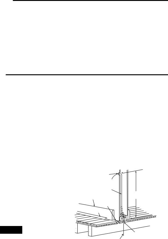
3.Probe for obstructions in partition before drilling 1⁄2” hole in wall at selected location. Take up quarter round and drill a small guide hole for sighting (see
fig. 1). From basement, drill 3⁄4” hole in partition floor next to guide hole. In houses without basements, drill 1⁄2” hole through ceiling and into partition from above (see fig. 1).
4.Through this hole drop a light chain, or 6” chain attached to a strong cord. Snag cord in basement with hooked wire. In houses without basements, drop cord through hole in ceiling and down partitioning; snag cord at the thermostat location.
5.Attach thermostat wires to cord and pull thermostat wires through hole in wall so that 6” of wire protrudes.
1⁄2” hole for |
|
|
thermostat wire |
|
|
Stout cord with 6” |
|
|
chain attached |
|
|
Baseboard |
Approximately |
|
5 feet from floor |
||
strip moulding |
||
|
||
1⁄4” guide hole |
|
|
for sighting |
|
|
Quarter round |
|
|
removed |
|
3⁄4” hole in floor of partition
Hooked wire for snagging chain
Figure 1. Routing thermostat wires
2
 Loading...