


XTR-335

OWNER’S MANUAL
INTRODUCTION
XTR-145/265/335
™
TToottaall BBaanndd PPrrootteeccttiioon
™
n
LASER-RADAR
DETECTOR
The Whistler Group Corporate Headquarters
3604 NW Frontage Rd. • Bentonville, AR 72712
Tel 479.273.6012 • Fax 479.273.2927
Whistler Customer Return Center
551 N. 13th St. • Rogers, AR 72756
Customer Service Tel 800.531.0004
www.whistlergroup.com
P/N 2060018, ©2009 The Whistler Group, Inc.
Dear Whistler Owner,
If you have questions concerning the
operation of this Whistler product
please call:
CuSTOmer SeRVICE
1-800-531-0004
Monday - Friday • 8:00 am - 5:00 pm CT
or visit our website
www.whistlergroup.com
Please keep the receipt in a safe place.
You may register your product online
at www.whistlergroup.com. For warranty
verification purposes, a copy of your dated
e receipt must accompany any unit sent
stor
in for warranty work. If the unit is
returned without a dated store receipt, an
out of warranty service charge applies.
Note: Your warranty period begins at
the time of purchase. The warranty
is validated only by the dated store
receipt!
Please record the serial
number of the unit in the space
provided in the warranty section of the
manual.
To fully acquaint yourself with the
operation of your Whistler detector
and to better understand the
differences between detecting radar,
laser and safety radar signals, we
recommend reading this entire
manual or visiting our FAQ page on
our website www.
whistlergroup.com
Enjoy your Whistler detector and
please drive safely.
Sincerely,
The Whistler Group, Inc.
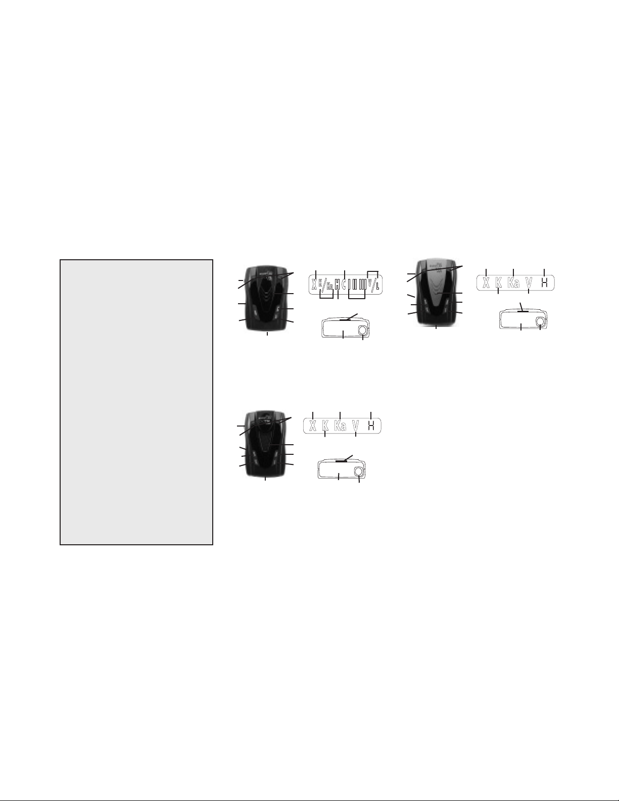
TABLE OF CONTENTS
Model Features Summary................................. 3 - 6
nstallation....................................................... 7 - 8
I
•
Mounting Guidelines 7
•
Windshield Mounting 7
•
Power Connection And Fuse Replacement 8
Operation....................................................... 8 - 12
•
Power On Self Test & Volume 8
•
Integrated Real Voice
•
Feature Engaged Confirmation 9
•
Self Test Mute 9
•
Setting Saver 9
•
Auto Quiet Mode 9
•
Quiet Mode 9
•
City/City 1/City 2 Modes 10
•
Highway Mode 10
•
Twin Alert Periscopes 11
•
Dim/Dark Modes 11
•
Engaging/Disengaging VG-2 Detection 11
•
Vehicle Battery Saver Mode 12
•
Stay Alert 12
Laser & Radar Alerts..................................... 13 - 14
•
Laser Audio/Visual Alerts 13
•
Laser Tips 13
•
Pulse Protection
•
Safety Warning System
VG-2 Alerts......................................................... 14
POP™Mode....................................................... 15
Option Select Mode........................................... 15
•
Reset Features 16
Troubleshooting Guide................................. 16 - 17
•
Care & Maintenance 17
Are Detectors Legal?......................................... 18
•
FCC Information 18
Speed Facts.................................................. 19 - 21
•
Radar Facts 19
•
Laser Facts 19-20
•
Other Speed Detection Systems 20 - 21
Warranty Information................................... 22 - 24
Specifications..................................................... 25
Accessories......................................................... 26
®
®
®
8
13
14
XTR-145 FEATURES
14
1
6
9
8
Features of XTR-145
• Total Band Protection
• Icon Display
• 360° Protection
• VG-2 Cloaking
• 3 City Modes
12b
2
11
7
12
™
• Quiet/Auto Quiet Mode
• Vehicle Battery Saver
• Alert Priority
• Twin Alert Periscopes
XTR-335 FEATURES
14
1
6
9
10
8
12a
Features of XTR-335
• Total Band Protection
• Numeric Icon Display
• Detects POP
• 360° Protection
oice
• Real V
• VG-2 Cloaking
• 3 City Modes
12b
2
11
7
• Quiet/Auto Quiet Mode
™
• Dim/Dark Mode
™
Mode
®
• Stay Aler
• Setting Saver
• Vehicle Battery Saver
•
• Aler
• Twin Alert Periscopes
34
20 17
15
Safety W
t Priority
18
19
3
4
16
17,18,19, 22
21
3
4
5
t
ning System
ar
XTR-265 FEATURES
14
13
1
12b
6
9
0
1
8
2
11
7
12a
5
™
™
Features of XTR-265
• Total Band Protection
• Numeric Icon Display
• Detects POP
• 360° Protection
• VG-2 Cloaking
• 3 City Modes
• Quiet/Auto Quiet Mode
™
Mode
• Dim/Dark Mode
™
• Stay Alert
• Setting Saver
• Vehicle Battery Saver
• Safety Warning System
• Alert Priority
• Twin Alert Periscopes
6
1
17,18,19, 22
15
21
3
4
5
™
™

FEATURE DESCRIPTIONS
Whistler’s ergonomic and user-friendly design
rovides a new level of operating convenience. Special
p
features include:
Note: Not all units have all features listed.
1. Bracket Release Button –
and easy release of the mounting bracket.
2. Speaker – provides distinct audio warnings
or X, K, Ka band radar, safety radar, laser
f
and VG-2.
ounting Bracket Location
3. M
ounting bracket firmly.
m
adar Antenna
4. R
antenna receives radar signals.
5. Front Laser – high gain optical lens
provides increased sensitivity and field of
view for leading-edge laser detection.
6. Rear Laser – an integrated optical
waveguide provides superior detection of
laser signals transmitted from behind.
7. City Button - reduces the annoyance of
false alerts typically encountered in urban
driving areas.
8. Quiet Button - pressing QUIET before a
radar signal is detected engages Auto
Quiet Mode which provides “clicking”
sounds after the initial warning. Pressing
QUIET during a radar encounter silences
audio alerts, while allowing visual alerts to
keep you informed.
9. Power / Volume Control – turns unit on/off
and adjusts audio level.
10. Dim Dark - engages Dim/Dark modes
11. Menu Button - (XTR-145) turns VG2 on/off.
(XTR-265/335) enters option select mode.
Icon Display -offers easy-to-r
12.
indicate power, city mode, radar band
identification, and signal strength.
– compact, high-eff
provides quick
– slot holds
iciency
ead display to
56
FEATURE DESCRIPTIONS
12a. Numeric Icon Display (XTR-265/335)
ombines icon display with a 7 segment digital
c
display that shows signal strength indication
and band identification.
2b. Dual Alert LED Periscope - provides
1
additional visual alerts.
13. VG-2/Laser Icon – indicates the unit is
receiving V
14. X-band Icon - indicates the unit is receiving
a X-band signal.
5. K-band Icon -indicates the unit is receiving
1
a K-band signal.
16. Ka-band Icon - indicates the unit is receiving
a Ka-band signal.
17. H - indicates unit is in Highway mode.
18. C - City Icon - indicates that the unit is
operating in city mode.
19. Signal Strength Icon - indicates the strength
of the signal being detected.
20. K/Ka-band Icon - shows the unit is receiving
a K or Ka band signal. K/Ka indicator will
flash for Ka band.
21. V - indicates that the unit is receiving a
VG-2 signal. Indicates that VG-2 is
engaged.
22. L - indicates that the unit is receiving a laser
signal.
Total Band Protection™- Complete Band
•
Coverage that detects laser, radar, VG-2 and safety
radar bands.
G-2 or laser signals.
INSTALLATION
Mounting Guidelines
•
Mount the unit as low as possible near the center of
he windshield.
t
•
Do not mount the unit behind wipers, ornaments,
mirrored sunscreens, etc. These obstructions have
aces which can affect radar and laser
metal surf
signals and reduce critical warning time.
(Regular tinted glass does not affect reception.)
•
Some windshields have an Instaclear™or Electriclear
ype coating, which affects radar signals. Consult
t
your dealer or the owner’s manual to determine if
your windshield has this coating.
•
Avoid placing unit in direct contact with the wind
shield.
•
To reduce the possibility of theft, conceal the unit
when not in use.
Windshield Mounting
•
Install the two suction cups and rubber bumper onto
the bracket by fitting them into their holes.
•
Press the suction cups onto the windshield at the
location you have chosen.
IMPORTANT: Some newer cars have a plastic
safety coating on the inside of the windshield. The
windshield bracket may leave permanent marks on
this type of surface.
type of windshield, check the owner’s manual or ask
To find out if your vehicle has this
your dealer. We recommend that you do not leave
the suction cup bracket on the windshield in direct
sunlight. If the detector is removed, this may cause
blistering of the dash in some vehicles.
7
™
 Loading...