


 BCP-3
BCP-3
Hydronic Multi-Stage Boiler Control
INSTALLATION AND OPERATION INSTRUCTIONS
Hot Water Control with Outdoor Reset, Set Point, and DHW for Hydronic Applications
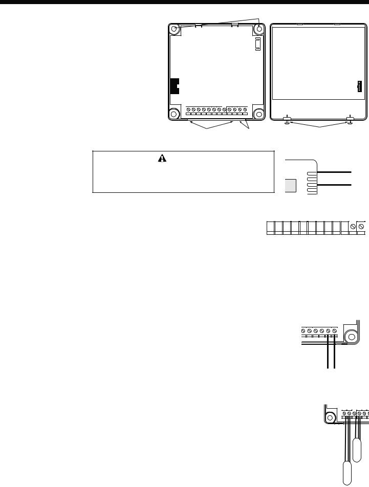
2 Line Alphanumeric Display |
Black (120VAC power) |
Displays sensor values and |
Output Lights indicate |
menu settings |
|
|
output status |
BCP-3
SYSTEM |
= |
147F |
|
TARGET |
= |
150F |
|
|
|
|
|
Boiler |
SYS |
DHW |
|
Pump |
Pump |
||
Output 1 |
|||
Output 2 |
Output 3 |
SET
Yellow (Output 1)
Blue (Output 2)
White (Output 3)
Display Section Locking Screws
The BCP-3 is a multi-boiler or multi-stage outdoor reset hydronic heating control. It establishes ambient comfort by varying the temperature of the heating system’s circulating hot water in response to changes in the outdoor temperature. In addition, it provides an outdoor temperature based cutoff, heating system pump control, and domestic hot water (DHW) pump control. Two unique features have been added to this control including a customized reset ratio curve. A Set Point option was added for applications where outdoor reset will not apply.
Two sensors are used, one to monitor the outdoor temperature and one to monitor the circulating hot water temperature in the heating system. When the outdoor temperature falls below the outdoor cutoff setting, the heating system is activated and the target water temperature is increased proportionally to satisfy the load. Should it get warmer outdoors, the target water temperature is automatically lowered by the control. If the outdoor temperature continues to rise to the outdoor cutoff setting then the heating system is turned off.
Because of the many different physical characteristics of buildings including the type of radiation; i.e., baseboard or radiant, the heat loss varies. In one building, a 1-degree outdoors temperature change may require a change of 1 degree in heating water temperature; for another it may require a change of 2, 3, or even 4 degrees in order to gain the desired comfort level. This is known as the Reset Ratio. The Reset Ratio chart shows the wide range of Reset Ratios available for the BCP-3 in addition to the customized reset ratio. See page 2.
The installer fits the BCP-3 to a specific building by adjusting the Reset Ratio curve. With curve number 4 (2:1 reset ratio) a 2-degree change in outdoor temperature will change the circulating hot water temperature by 1 degree; at curve number 11(1:3 reset ratio) an outdoor change of 1 degree will change the water temperature by 3 degrees. Most buildings with baseboard radiation require a curve of 6, 7, or 8. Radiant heat applications usually require a lower curve. An external T-Stat input can be used to shut the heating system down when the
 WARNING This Weil McLain control is strictly an operating control; it should never be used as a primary limit or safety control. All equipment must have its own certified limit and safety
controls required by local codes. The installer must verify proper operation and correct any safety problems prior to the installation of this Weil McLain control.
Part Number 550-110-070/0308

BCP-3 Installation and Operation Manual
thermostat is satisfied. Another, is a Setback input that will switch the heating system to a lower set point determined by the Set Back setting.
Type of Radiation in Building |
Reset Ratio |
Offset |
Radiators (Steel & Cast Iron) |
1.00 (O) : 1.00 (S) |
0˚F |
Baseboard (Finned copper tube& Cast Iron) |
1.00 (O) : 1.00 (S) |
0˚F |
Radiant (High Mass/Concrete) |
4.00 (O) : 1.00 (S) |
-10˚F |
Radiant (Low Mass/Joists) |
2.00 (O) : 1.00 (S) |
-10˚F |
Fan Coils & Air Handlers |
1.00 (O) : 1.00 (S) |
20˚F |
An optional domestic hot water input is provided for systems where an indirect tank provides DHW. During a DHW call, the BCP-3 will maintain a constant set point of 200°F or the Maximum Water Temperature setting, whichever is lower, regardless of outdoor temperature or the status of the heating system. If 1-On/Off+2-Pumps Output Mode option was selected, the DHW pump will be enabled whenever there is a call for DHW. In addition, the heating system pump can be programmed to turn off during a DHW call for up to 120 minutes to satisfy the DHW demand quicker while withholding building heat.
Operation Concept
|
|
|
|
1:4 |
1:3 |
|
1:2 |
|
1:1.5 |
|
|
|
220 |
|
|
12 |
11 |
|
10 |
|
9 |
|
|
|
|
|
|
|
|
|
|
|
|
|
|
|
210 |
|
|
|
|
|
|
|
|
8 |
1:1.25 |
°F) |
200 |
|
|
|
|
|
|
|
|
|
|
190 |
|
|
|
|
|
|
|
|
7 |
1:1 |
|
(in |
|
|
|
|
|
|
|
|
|||
|
|
|
|
|
|
|
|
|
|||
180 |
|
|
|
|
|
|
|
|
|
|
|
Temperature |
|
|
|
|
|
|
|
|
|
|
|
170 |
|
|
|
|
|
|
|
|
6 |
1.25:1 |
|
160 |
|
|
|
|
|
|
|
|
5 |
1.5:1 |
|
|
|
|
|
|
|
|
|
|
|||
150 |
|
|
|
|
|
|
|
|
4 |
2:1 |
|
|
|
|
|
|
|
|
|
|
|||
Water |
140 |
|
|
|
|
|
|
|
|
||
|
|
|
|
|
|
|
|
|
|
||
130 |
|
|
|
|
|
|
|
|
3 |
3:1 |
|
|
|
|
|
|
|
|
|
|
|||
|
120 |
|
|
|
|
|
|
|
|
2 |
4:1 |
|
110 |
|
|
|
|
|
|
|
|
1 |
8:1 |
|
100 |
|
|
|
|
|
|
|
|
|
|
|
70 |
60 |
50 |
40 |
30 |
20 |
10 |
0 |
-10 |
-20 |
|
Outdoor Temperature (in °F)
Reset Ratio Curves
Reset Ratios are presented as
Outdoor : Water
The BCP-3 has multiple Output Modes of operation. It can control any three output boiler-and-pump variety ranging from a single On/Off boiler with a system pump to three individual boilers. In addition, it can accepts a DHW call signal to raise the target set point. Moreover, if "1-On/Off+2-Pump" is selected as an Output Mode, it will control the DHW pump allowing it to energize on a DHW call. (See Output Mode Table under the Startup Menu on page 4.)
Boiler Operation
•When a single On/Off boiler is selected as the primary function of the BCP-3, the boiler relay will energize when the System Sensor reading is below the Target temperature less the Differential. Moreover, the Outdoor Sensor reading must be below the Outdoor Cutoff setting and the EXT+/EXT- (Enable/Disable) terminals must be shorted using a dry-contact switch or a jumper. If the System temperature exceeds the Target, the boiler relay will de-energize.
•If sequencing multiple stages or boilers are the primary function of the BCP-3, the BCP-3 will use the Purge Delay to start the lead boiler. Then, it will use the Reaction Time to add additional stages or boilers. When subtracting stages, the BCP-3 will use only the Minimum Run Time.
System Pump Operation
•When the BCP-3 is in one of the Output Modes that control the System Pump relay while the EXT+/EXT- (Enable/Disable) terminals are shorted using a dry-contact switch or a jumper, the System Pump relay will energize, as long as the Outdoor Sensor reading is below the Outdoor Cutoff setting. However, upon the opening of the EXT+/EXT- (Enable/Disable) terminals or if the Outdoor Sensor reading rises two degrees above the Outdoor Cutoff setting, all boiler relays will de-energize and the System Pump relay will remain energized for the Run-On delay period before de-energizing.
•If DHW Priority was set to other than "NO", a DHW call using terminals T3+/T3- (DHW call Input) will de-energize the System Pump relay for the period of the DHW priority or the termination of the DHW call, whichever comes first. This will ensure all boiler outputs are directed to produce domestic hot water.
•If DHW Priority was set to "NO", then a DHW call will not have any effect on the System Pump relay.
DHW Pump Operation
•When the BCP-3 is controlling the DHW Pump relay by selecting "1-On/Off+2-Pump" mode from the Output Modes, a DHW call using terminals T3+/T3- (DHW call Input) will energize the DHW Pump relay. In addition, the BCP-3 will raise the Target temperature to the lower of 200˚F or the Maximum Water temperature Setting.
•When the BCP-3 is in Outdoor Cutoff or when the EXT+/EXT- (Enable/Disable) terminals are open, a DHW call will energize only the DHW Pump relay in a DHW Priority setting. See Output Mode Table on page 4. However, if No DHW Priority was selected, both the System and DHW Pumps will energize on a DHW call.
2
BCP-3 Installation and Operation Manual
Mounting the Controller
Base Section |
Display Section |
Base Mounting Holes
• The BCP-3 is designed to mount on a 1900 (4”x4”) deep electrical box.
•If additional room is needed for wiring use the extension skirt provided.
•Place the BCP-3 in an indoor convenient location near the unit to be controlled and away from excessive heat or cold.
• Partially unscrew the Display Cover Mounting screws. |
|
|
|
This allows for its removal. |
|
|
|
• Lifting the Display Section away from the base starting |
|
|
|
with the bottom will unplug it from the Base section. |
|
|
|
• Proceed with the power and output wiring instructions. |
T1 COM T2 COM T3+ T3EXT+ EXT- P+ P- COM 24VAC |
|
|
• Use the screws provided to mount the BCP-3 to the |
|
|
|
1900 box or the extension skirt. |
|
Input Terminals 24VAC optional power input |
Display Cover Mounting Screws |
• Mount Display Section back to the Base Section. |
|
|
|
Tighten the Display Cover Mounting Screws. |
|
120VAC Power Wiring |
|
|
|
|
|
|
|
WARNING |
|
|
The BCP-3 can accept only one source of power: |
BLACK |
|
Wiring |
120VAC or 24VAC. If more than one power source is |
120VAC Power Source |
|
applied, the unit may be damaged. |
BLACK |
||
Wiring Power Input
The BCP-3 is designed to accept ONLY A SINGLE POWER SOURCE. It can be wired to
either 120VAC using the two Black wires or 24VAC using the right most two terminals on the Input Terminals terminal block on bottom of the control. Weil McLain recommends the installation of a Surge
Suppressor and a Power Switch before the Power Line connection for safety and ease of service. 


T1 COM T2 COM T3+ T3EXT+ EXT- P+ P- COM 24VAC
120VAC
•Attach line voltage, 120VAC, to the two Black wires extending from the back of the BCP-3. Remember to use the power line from a different source than the equipment being controlled.
24VAC
•Use a dedicated transformer with at least a 5VA output.
•Bring 24VAC to the two right most terminals on the front of the BCP-3 marked 24VAC and COM.
System Sensors { |
Outdoor Sensor { |
DHW Input Dry-Contact { |
Enable/Disbale Input Dry-Contact { |
Setback Input Dry-Contact { |
24VAC power Input { |
24VAC Power Wiring
Wiring Input Terminals
Heating System Sensor (HSS) Installation (T1, COM)
Locating HSS
•Place the Heating System sensor in the common header where it will register the output of the boilers before any takeoffs.
•Only use the Standard Brass Tube sensor provided.
•The sensor wires can be extended up to 500' using a shielded 2-conductor cable (Belden #8760 or equivalent (#18/2)).
EXT+ EXT- |
P+ |
P- COM 24VAC |
Comm |
24VAC |
24VAC Power Source
•Cut the shield and do not connect it at the sensor end. Only connect it at the control end using the outdoor terminal marked COM. Do not ground the shield at the sensor but at the control using the COM terminal.
•Do not run sensor wires in conduit with line voltage wiring.
Sensor Wiring
T1 COM |
T2 COM T3+ |
T |
Immersion Heating System Sensor (HSS) Installation
•Install a 3/8"ID x 1/2"NPT immersion well.
•Insert the supplied sensor probe into the well.
Shield |
Shield |
|
Outdoor Sensor |
Strap-On Heating System Sensor (HSS) Installation
•Strap the sensor to the pipe using a metal clamps. Do not over tighten the clamp.
•Strap pipe insulation around the sensor and the pipe.
System Temp
3

BCP-3 Installation and Operation Manual |
|
IMPORTANT |
|
Determining the proper location for the Outdoor Sensor is very important. |
|
The BCP-3 will base the heat on the outdoor temperature information it |
Sensor Clip |
Outdoor Sensor |
|
receives from this location. If the sensor is in the sun, or covered with |
|
ice, its reading will be different from the actual outdoor temperature. |
|
Outdoor Sensor Installation (T2, COM) |
|
|
• The Outdoor Sensor must be used when Outdoor Reset is selected as the Control Mode |
|
|
from the Startup menu. However, in Set Point mode, the Outdoor Sensor is optional. |
|
|
When connected in that mode, it will be used as an input for the Outdoor Cutoff only. |
|
|
• Only use the Weil McLain sensor included with the unit. |
10' Minimum |
|
• Place the sensor in the shade on the north side of the building. |
|
|
• Be sure the location is away from doors, windows, exhaust fans, vents, or other heat |
|
|
sources. |
|
|
• The sensor should be mounted approximately 10' feet above ground level. |
|
|
• Mount the sensor clip base to the outside of the building. Insert the sensor in the middle |
|
|
and snap close the second clip on the sensor. |
|
|
• The sensor wires can be extended up to 500' using shielded 2-conductor cable. |
|
|
• Cut the shield and do not connect it at the sensor end. Only connect it at the control end |
|
Low Voltage |
using the outdoor terminal marked COM. |
|
|
|
Sensor Wires |
|
• Do not run sensor wires in conduit with line voltage wiring. |
|
|
Wiring the Domestic Hot Water Call DHW (T3+, T3-) |
|
|
• A DHW call will raise system Set Point to 200°F or Maximum Target temperature, |
|
|
whichever is lower. |
|
DHW Call |
• When "1-On/Off+2-Pump" is selected as the Output Mode from the Startup menu, the BCP-3 can control the |
||
operation of the Domestic Hot Water (DHW) pump using Output 3. See Output Mode Table on page 4. |
Wiring |
|
|
||
• DHW Call terminals are dry contact N.O. terminals. |
|
|
• Wire an aquastat or another control to provide dry contact closure on the DHW Call terminals. |
T1 COM T2 COM T3+ T3EXT+ EXT- |
|
Wiring the Enable/Disable (TSTAT) (EXT+, EXT-)
•The EXT terminals can be used to enable or disable the heat to the system by connecting it to a thermostat, external control, or a switch. It accepts dry contact input only.
•If no thermostat or control is connected to the EXT terminals, leave the jumper supplied connected.
•No outputs will be active unless the EXT terminals are closed/shorted.
Enable/Disable
Wiring
Wiring the Setback/Boost (P+, P-)
•The Setback feature can be used to provide the BCP-3 with a lower temperature Set Point when less heat is required during night or unoccupied periods.
COM T3+ T3EXT+ EXT- P+ P- COM
•The Setback is activated by closing/shorting the P+ and P- terminals using an external control, i.e. timer or switch.
Wiring Outputs
Wire Colors and Output Lights
•The BCP-3 has a three S.P.S.T. (N.O.) output relays. Each relay is rated at 1A Inductive load (1/8 HP).
•The BCP-3 has three LED lights that follow the output relays' operation. When a relay energizes, its LED will turn on. When the relay de-energizes, its LED will turn off.
•The outputs are dry contacts only. They do not source any power.
•The two Yellow wires represent Output 1 relay and the left LED.
•The two Blue wires represent Output 2 relay and the middle LED.
•The two White wires represent Output 3 relay and the right LED.
•Depending on the Output Mode of operation selected during the Startup, the function of each
output will vary. See Output Mode Table for output wire colors and functions on page 4. |
Boiler |
|
Output 1 |
Setback/Boost
Wiring
3+ T3EXT+ EXT- P+ P- COM 24VAC
SYS |
DHW |
Pump |
Pump |
Output 2 |
Output 3 |
4
BCP-3 Installation and Operation Manual
Output Mode Table
|
|
Output 1 |
Output 2 |
Output 3 |
|
Output Mode |
Description |
(Yellow |
(Blue |
(White |
Notes |
|
|
Wires) |
Wires) |
Wires) |
|
1-On/Off+1-Pump |
One On/Off boiler and a System pump |
Sys Pump |
Boiler |
Not used |
|
1-On/Off+2-Pump |
One On/Off boiler, a System pump and |
Sys Pump |
Boiler |
DHW |
|
|
a Domestic Hot Water Pump |
|
|
Pump |
|
|
|
|
|
|
DHW Pump |
2-On/Off+1-Pump |
Two On/Off boilers and a System pump |
Sys Pump |
Boiler 1 |
Boiler 2 |
controlled by DHW |
|
|
|
|
|
Aquastat |
|
|
|
|
|
DHW Pump |
1-Lo/Hi+1-Pump |
One Lo/Hi boiler and a System pump |
Sys Pump |
Boiler Lo |
Boiler Hi |
controlled by DHW |
|
|
|
|
|
Aquastat |
|
|
|
|
|
Sys Pump controlled |
3-On/Off |
Three On/Off boilers and NO pumps |
Boiler 1 |
Boiler 2 |
Boiler 3 |
using other controls |
|
|
|
|
|
or run constantly. |
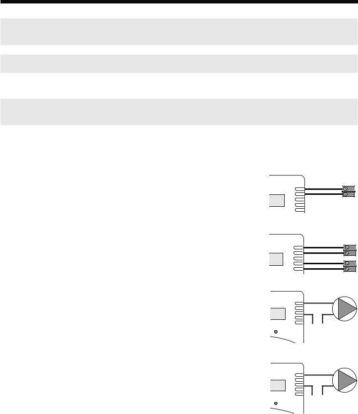
Wiring the Boiler Output
Single-Stage (On/Off) Boiler Wiring
•If any of the "1-On/Off" Output Modes is selected, wire the two Blue wires to the boiler circuit.
•If more than one On/Off boiler is to be controlled by the BCP-3, follow the wiring colors as per the Output Mode Table above.
•The BCP-3 does not source any output power to the boiler. The relay makes when energized.
Two-Stage (Lo/Hi) Boiler wiring
•Wire the two Blue wires to the boiler control circuit initiating the Low Fire signal.
•Then, wire the two White wires to the High fire circuit.
• The BCP-3 does not source any output power to the boiler. The relay makes when energized.
On/Off Boiler
Output Wiring
Blue
Two-Stage Boiler
Output Wiring
Blue (Lo Fire)
White (Hi Fire)
Wiring the System and DHW Pump Outputs
System Pump Wiring (Not Available With "3-On/Off" Output Mode)
•The BCP-3 will control the System Pump relay (Maximum of 1/8 HP) in all Output Modes except (3-On/Off), as all outputs will be used by boiler stages. In this scenario, the system pump can be controlled independently using a switch or left to run constantly.
• Wire the two Yellow wires to the System Pump circuit.
• The BCP-3 does not source any output power to the pump. The relay makes when energized to switch the power to the pump on.
DHW Pump Wiring (Available Only With "1-On/Off+2-Pumps" Output Mode)
System Pump
Output Wiring
YELLOW
L N
120VAC
DHW Pump
Output Wiring
•The BCP-3 will control the DHW Pump relay (Maximum of 1/8 HP) only in (1-On/Off+2-Pump)
Output Mode. In the other modes, the DHW pump can be controlled using an external DHW aquastat.
•If the BCP-3 is controlling the DHW pump, wire the two White wires to the DHW Pump circuit.
• The BCP-3 does not source any output power to the pump. The relay makes when energized to switch the power to the pump on.
WHITE
L N
120VAC
5
 Loading...