


Model No. WESY2916.1
Serial No.
Write the serial number in the space above for future reference.
Seri al
al Number
 Decal (under seat)
QUESTIONS?
As a manufacturer, we are committed to providing complete customer satisfaction. If you have questions, or if a part is damaged or missing, PLEASE CONTACT OUR CUSTOMER SERVICE DEPARTMENT DIRECTLY.
CALL TOLL-FREE:
1-877-992-5999
Mon.–Fri., 6 a.m.–6 p.m. MST
ON THE WEB:
www.weiderservice.com
 CAUTION
Read all precautions and instructions in this manual before using this equipment. Save this manual for future reference.
USER’S MANUAL

 Visit our website at
www.weiderfitness.com
new products, prizes, fitness tips, and much more!

TABLE OF CONTENTS
IMPORTANT PRECAUTIONS . . . . . . . . . . . . . . . . . . . . . . . . . . . . . . . . . . . . . . . . . . . . . . . . . . . . . . . . . . . . . . . . 3 BEFORE YOU BEGIN . . . . . . . . . . . . . . . . . . . . . . . . . . . . . . . . . . . . . . . . . . . . . . . . . . . . . . . . . . . . . . . . . . . . . . 4 PART IDENTIFICATION CHART . . . . . . . . . . . . . . . . . . . . . . . . . . . . . . . . . . . . . . . . . . . . . . . . . . . . . . . . . . . . . .5 ASSEMBLY . . . . . . . . . . . . . . . . . . . . . . . . . . . . . . . . . . . . . . . . . . . . . . . . . . . . . . . . . . . . . . . . . . . . . . . . . . . . . . 8 ADJUSTMENTS . . . . . . . . . . . . . . . . . . . . . . . . . . . . . . . . . . . . . . . . . . . . . . . . . . . . . . . . . . . . . . . . . . . . . . . . . . 25 WEIGHT RESISTANCE CHART . . . . . . . . . . . . . . . . . . . . . . . . . . . . . . . . . . . . . . . . . . . . . . . . . . . . . . . . . . . . . .27 CABLE DIAGRAM . . . . . . . . . . . . . . . . . . . . . . . . . . . . . . . . . . . . . . . . . . . . . . . . . . . . . . . . . . . . . . . . . . . . . . . . .28 MAINTENANCE . . . . . . . . . . . . . . . . . . . . . . . . . . . . . . . . . . . . . . . . . . . . . . . . . . . . . . . . . . . . . . . . . . . . . . . . . .29 EXERCISE GUIDELINES . . . . . . . . . . . . . . . . . . . . . . . . . . . . . . . . . . . . . . . . . . . . . . . . . . . . . . . . . . . . . . . . . . .30 PART LIST . . . . . . . . . . . . . . . . . . . . . . . . . . . . . . . . . . . . . . . . . . . . . . . . . . . . . . . . . . . . . . . . . . . . . . . . . . . . . .33 EXPLODED DRAWING . . . . . . . . . . . . . . . . . . . . . . . . . . . . . . . . . . . . . . . . . . . . . . . . . . . . . . . . . . . . . . . . . . . .34 ORDERING REPLACEMENT PARTS . . . . . . . . . . . . . . . . . . . . . . . . . . . . . . . . . . . . . . . . . . . . . . . . . .Back Cover LIMITED WARRANTY . . . . . . . . . . . . . . . . . . . . . . . . . . . . . . . . . . . . . . . . . . . . . . . . . . . . . . . . . . . . . . Back Cover
WEIDER is a registered trademark of ICON IP, Inc.
2
IMPORTANT PRECAUTIONS
 WARNING: To reduce the risk of serious injury, read the following important precautions before using the weight system.
1.Read all instructions in this manual and all warnings on the weight system before using the weight system. Use the weight system only as described in this manual.
2.It is the responsibility of the owner to ensure that all users of the weight system are adequately informed of all precautions.
3.The weight system is intended for home use only. Do not use the weight system in any commercial, rental, or institutional setting.
4.Keep the weight system indoors, away from moisture and dust. Place the weight system on a level surface, with a mat beneath it to protect the floor or carpet. Make sure that there is enough clearance around the weight system to mount, dismount, and use the weight system.
5.Inspect and properly tighten all parts regularly. Replace any worn parts immediately.
6.Keep hands and feet away from moving parts.
7.Keep children under age 12 and pets away from the weight system at all times.
8.Always wear athletic shoes for foot protection while exercising.
9.Make sure that the cable remains on the pulleys at all times. If the cable binds as you are exercising, stop immediately and make sure that the cable is on the pulleys. Replace all cables at least every two years.
10.The weight system is designed to be used only with the included weight. Do not use the weight system with dumbbells or any other type of weight to increase the resistance.
11.The weight system is designed to support a maximum user weight of 300 pounds.
12.Always make sure that the weight pin is inserted fully into the weight stack before exercising.
13.If you feel pain or dizziness while exercising, stop immediately and begin cooling down.
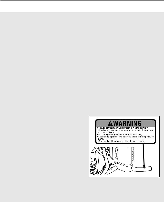
14.The decal shown below has been placed on the weight system. If the decal is missing or illegible, call the toll-free telephone number on the front cover of this manual and order a free replacement decal. Apply the decal in the location shown.
 WARNING: Before beginning this or any exercise program, consult your physician. This is especially important for persons over the age of 35 or persons with pre-existing health problems. Read all instructions before using. ICON assumes no responsibility for personal injury or property damage sustained by or through the use of this product.
3

BEFORE YOU BEGIN
Thank you for selecting the versatile WEIDER® 3130 weight system. The weight system offers a selection of weight stations designed to develop every major muscle group of the body. Whether your goal is to tone your body, build dramatic muscle size and strength, or improve your cardiovascular system, the weight system will help you to achieve the specific results you want.
For your benefit, read this manual carefully before using the weight system. If you have questions after
reading this manual, please see the front cover of this manual. To help us assist you, note the product model number and serial number before contacting us. The model number is WESY2916.1. The serial number can be found on a decal attached to the weight system (see the front cover of this manual).
Before reading further, please review the drawing below and familiarize yourself with the parts that are labeled.
ASSEMBLED DIMENSIONS:
Height: 83 in. (210 cm)
Width: 43 in. (109 cm)
Depth: 77 in. (196 cm)
Lat Bar
Butterfly Arm
Right Side
Backrest
Press Arm
Curl Pad 
Curl Adjustment Knob 

Leg Lever


Foam Pad 
Note: The terms “right side” and “left side” are determined relative to a person facing away from the weight system; they do not correspond to right and left on the drawings in this manual.
Shroud
Left Side
Backrest
Adjustment Knob
Weight
Frame
Seat
Seat Adjustment Knob
Ankle Strap
Handle
Chain
4

PART IDENTIFICATION CHART—Model No. WESY2916.1 R0107A
Refer to the drawings below to identify small parts used in assembly. The number in parentheses by each drawing is the key number of the part, from the PART LIST in the center of this manual. Note: Some small parts may have been preattached. If a part is not in the parts bag, check to see if it has been preattached. If a part is missing, call the toll-free number on the front cover of this manual.
M6 Nylon |
M8 Nylon |
M10 Nylon |
|
M4 Washer |
|
M12 Nut (112) |
(104) |
M6 Washer |
|||
Locknut (107) |
Locknut (78) |
Locknut (77) |
|
(114) |
|
|
|
M8 Washer (103)
M10 Washer (80) |
M10 Large Washer (105) |
M12 Large Washer (98) |
M4 x 12mm |
M4 x 16mm |
|
|
|
|
|
|
|
|
|
|
|
|
|
|
|
|
|
|
|
|
|
|
|
|
|
|
|
|
|
|
|
|
|
|||
|
|
|
|
|
|
|
|
|
|
|
|
|
|
|
|
|||
|
|
|
|
|
|
|
|
|
|
|
|
|
|
|
|
|||
M6 x 16mm |
|
|
|
|
|
|
|
|
|
|
||||||||
M8 x 22mm |
|
|
|
|
|
|
||||||||||||
Self-tapping |
Self-tapping |
Screw (88) |
|
|
M10 x 20mm |
|||||||||||||
Screw (102) |
Screw (110) |
|
|
|
|
|
|
Shoulder Bolt (90) |
|
|
||||||||
|
|
|
|
|
|
Button Screw (96) |
||||||||||||
|
|
|
|
|
|
|
|
|
|
|
|
|
|
|
|
|
|
|
|
|
|
|
|
|
|
|
|
|
|
|
|
|
|
|
|
|
|
|
|
|
|
|
|
|
|
|
|
|
|
|
|
|
|
|
|
|
|
|
|
|
|
|
|
|
|
|
|
|
|
|
|
|
|
|
|
|
|
|
|
|
|
|
|
|
|
|
|
|
|
|
|
|
|
|
M10 x 70mm Bolt (113) |
M10 x 75mm Button Screw (118) |
5
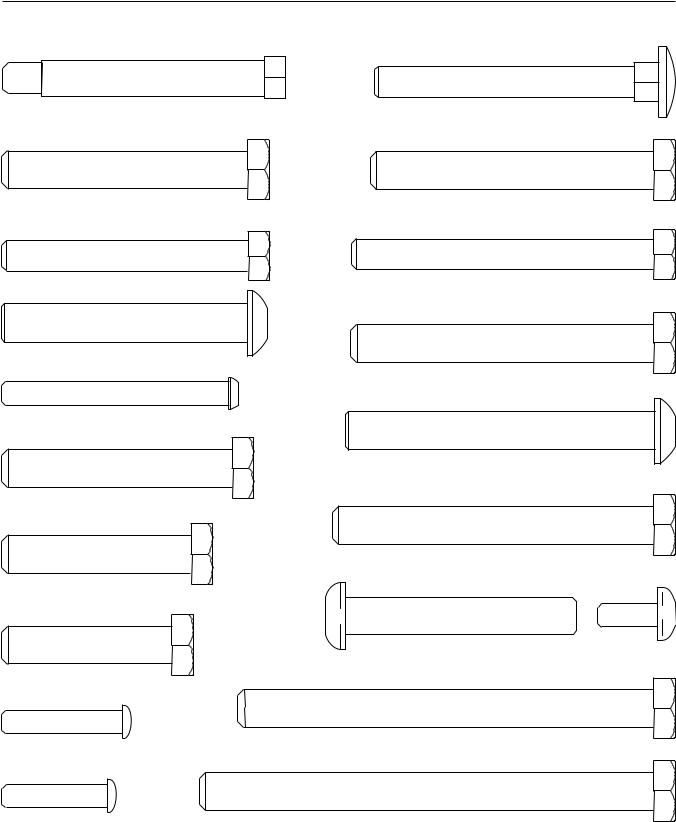
PART IDENTIFICATION CHART—Model No. WESY2916.0 R0107A
M8 x 69mm Shoulder Bolt (87)
M10 x 65mm Bolt (85)
M8 x 65mm Bolt (101)
M10 x 65mm Button Bolt (106)
M6 x 60mm Button Screw (91)
M10 x 60mm Bolt (79)
M10 x 50mm Bolt (97)
M10 x 45mm Bolt (86)
M6 x 32mm Screw (89)
M6 x 28mm
Bolt (94)
M8 x 75mm Carriage Bolt (83)
M10 x 75mm Bolt (82)
M8 x 80mm Bolt (100)
M10 x 80mm Bolt (84)
M10 x 82mm Button Screw (92)
M10 x 85mm Bolt (81)
M10 x 61mm Bolt Set (116)
M10 x 110mm Bolt (93)
M10 x 120mm Bolt (115)
6
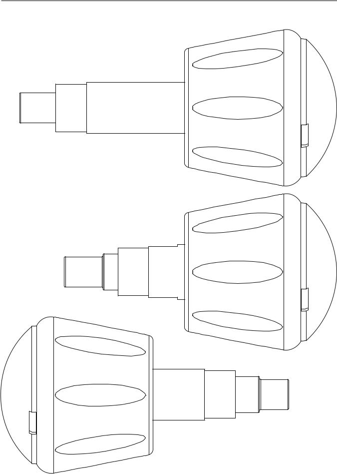
PART IDENTIFICATION CHART—Model No. WESY2916.1 R0107A
Backrest Adjustment Knob (53)
Curl Adjustment Knob (58)
Seat Adjustment Knob (52)
7

ASSEMBLY
Make Assembly Easier
Everything in this manual is designed to ensure that the weight system can be assembled successfully by anyone. Before beginning assembly, make sure to read the information on this page. This brief introduction will save you much more time than it takes to read it.
Assembly Requires Two Persons
For your convenience and safety, assemble the weight system with the help of another person.
Set Aside Enough Time
Due to the many features of the weight system, the assembly process will require several hours. By setting aside plenty of time and by deciding to make the task enjoyable, assembly will go smoothly. You may want to assemble the weight system over a couple of evenings.
Select a Location for the Weight System
Because of its weight and size, the weight system should be assembled in the location where it will be used. Make sure that there is enough room to walk around the weight system as you assemble it.
How to Unpack the Box
To make assembly as easy as possible, we have divided the assembly process into four stages. The parts needed for each stage are found in individual bags. Important: Wait until you begin each stage to open the parts bag for that stage. Place all parts of the weight system in a cleared area and remove the packing materials. Do not dispose of the packing materials until assembly is completed.
Make sure you have the following tools:
• Two adjustable wrenches
• One standard screwdriver
• One phillips screwdriver
• One rubber mallet
•You will also need grease or petroleum jelly, a small amount of soapy water, and clear tape or masking tape.
Note: Assembly will be more convenient if you have a socket set, a set of open-end or closed-end wrenches, or a set of ratchet wrenches.
How to Identify Parts
To help you identify the small parts used in assembly, we have included a PART IDENTIFICATION CHART in the center of this manual. Place the chart on the floor and use it to easily identify parts during each assembly step. Note: Some small parts may have been pre-attached. If a part is not in the parts bag, check to see if it has been pre-attached.
How to Orient Parts
As you assemble the weight system, make sure all parts are oriented exactly as shown in the drawings.
Tightening Parts
Tighten all parts as you assemble them, unless instructed to do otherwise.
Questions?
If you have questions after reading these assembly instructions, please see the front cover of this manual.
The Four Stages of the Assembly Process
Frame Assembly—You will begin by assembling |
Cable Assembly—During this stage you will |
the base and the uprights that form the skeleton of |
attach the cables and pulleys that connect the |
the weight system. |
arms to the weights. |
Arm Assembly—During this stage you will |
Seat Assembly—During the final stage you will |
assemble the arms and the leg lever. |
assemble the seats and the backrests. |
|
|
8
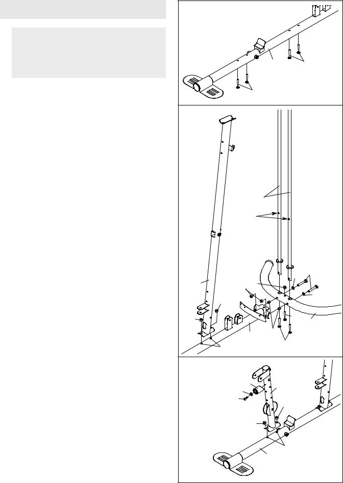
Frame Assembly |
1 |
|
|
|
|
|
|
|
|
1. |
|
|
|
|
Before beginning assembly, make sure you |
|
|
|
|
understand the information in the box on |
|
|
|
|
page 8. See the PART IDENTIFICATION |
|
|
|
|
CHARTS on pages 5 and 6 for help identify- |
|
|
1 |
83 |
ing small parts. |
|
|
||
|
|
|
|
|
Insert four M8 x 75mm Carriage Bolts (83) up |
|
83 |
|
|
through the Base (1). Note: It may be helpful to |
|
|
|
|
place a piece of tape over each Bolt head to |
2 |
|
|
|
hold it in place. |
|
|
|
|
|
|
|
|
|
2. Insert the two Weight Guides (18) into the |
|
|
|
|
Stabilizer (3). Make sure that the indicated |
|
|
|
|
holes in the Weight Guides are nearer the |
|
|
|
|
floor. |
|
|
|
|
Attach the Stabilizer (3) and the Weight Guides |
|
|
|
|
(18) to the base (1) with two M10 x 85mm Bolts |
|
|
|
|
(81), two M10 Washers (80), two 21mm Steel |
|
|
|
|
Spacers (108), and two M10 Nylon Locknuts (77). |
|
18 |
|
|
Do not tighten the Nylon Locknuts yet. |
|
|
|
|
Next, attach the Weight Guides (18) to the |
|
Holes |
|
|
Stabilizer (3) with two M10 x 20mm Button |
|
|
|
|
Screws (96). Then, attach the Stabilizer to the |
|
|
|
|
Base (1) with an M8 x 75mm Carriage Bolt (83) |
|
|
|
|
and an M8 Nylon Locknut (78). Do not tighten |
|
|
|
|
the Nylon Locknut yet. |
|
|
|
|
Attach the Upright (2) to the Base (1) with the two |
|
|
80 |
81 |
indicated M8 x 75mm Carriage Bolts (83) and two |
2 |
78 |
|
|
M8 Nylon Locknuts (78). Do not tighten the |
|
77 |
|
80 |
|
|
|
||
Nylon Locknuts yet. |
|
78 |
|
|
|
|
|
||
|
78 |
|
83 |
3 |
|
|
|
||
|
|
|
|
|
|
|
1 |
108 |
|
|
|
|
|
|
|
|
83 |
96 |
|
|
|
|
|
|
3. Attach the Front Leg (10) to the Base (1) with the |
3 |
|
|
|
two M8 x 75mm Carriage Bolts (83) and two M8 |
|
|
|
|
Nylon Locknuts (78). Do not tighten the Nylon |
|
75 |
10 |
|
Locknuts yet. |
|
|
||
|
104 |
|
||
|
|
|
|
|
Attach the Leg Lever Bumper (75) to the Front |
|
110 |
78 |
|
|
|
|
||
Leg (10) with an M4 x 16mm Self-tapping Screw |
|
|
|
|
(110) and an M4 Washer (104). Make sure the |
|
78 |
|
|
end of the Leg Lever Bumper is pointing up. |
|
|
|
|
|
|
|
|
|
|
|
|
83 |
|
|
|
|
1 |
|
|
9 |
|
|
|
4. Attach the Frame (9) to the Upright (2) with two |
4 |
|
|
|
M8 x 80mm Bolts (100), two M8 Washers (103), |
78 |
2 |
||
|
||||
and two M8 Nylon Locknuts (78). Do not tighten |
|
9 |
100 |
|
the Nylon Locknuts yet. |
|
|||
|
78 |
|||
|
|
103 |
||
Attach the Frame (9) to the Front Leg (10) with |
|
78 |
|
|
|
|
|
||
two M8 x 65mm Bolts (101), two M8 Washers |
|
78 |
|
|
(103), and two M8 Nylon Locknuts (78). Do not |
|
100 |
||
|
|
|||
tighten the Nylon Locknuts yet. |
|
|
103 |
|
|
|
|
||
|
103 |
10 |
|
|
|
|
|
||
|
101 |
|
|
|
5. Attach the bottom of the Left Shroud (21) to the |
5 |
|
|
|
Base (1) with two M4 x 12mm Self-tapping |
|
|
||
|
|
|
||
Screws (102). |
|
|
|
|
Repeat this step for the Right Shroud (not |
|
|
|
|
shown). |
|
|
|
|
|
|
1 |
|
|
|
|
21 |
|
|
|
|
102 |
|
|
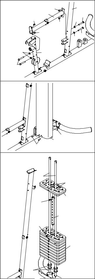
6. Note: Some parts have been removed to show |
6 |
|
|
|
this step clearly. |
|
|
||
|
|
|
||
Slide the two Weight Bumpers (71) onto the |
|
|
|
|
Weight Guides (18). Orient nine Weights (19) with |
|
18 |
|
|
the pin holes on the bottom as shown. Slide the |
|
|
||
|
|
|
||
Weights onto the Weight Guides. |
|
|
Grease |
|
Insert the Weight Tube into the nine Weights (19). |
|
|
|
|
Make sure that the pin on the Weight Tube is |
|
|
19 |
|
oriented as shown. |
|
Pin |
||
|
|
|||
Lubricate the indicated holes in a Weight (19) |
|
|
|
|
with the included grease packet. Slide the Weight |
|
20 |
|
|
onto the Weight Guides (18). |
|
Pin |
|
|
|
|
Hole |
|
|
|
|
|
19 |
|
|
|
71 |
|
10
7.Attach the Top Frame (4) to the Upright (2) with two M8 x 80mm Bolts (100), two M8 Washers (103), and two M8 Nylon Locknuts (78). Do not tighten the Nylon Locknuts yet.
Attach the Weight Guides (18) to the Top Frame
(4) with two M10 x 20mm Button Screws (96) and two M10 Washers (80).
8.Attach the top of the Left Shroud (21) to the Top Frame (4) with two M4 x 12mm Self-tapping Screws (102).
Repeat this step for the Right Shroud (22).
9.Attach a Shroud Cover (23) to the Left and Right Shrouds (21, 22) with two M6 x 28mm Bolts (94), four M6 Washers (114), and two M6 Nylon Locknuts (107).
Attach the Shroud Cover (23) to the Top Frame
(4) with four M4 x 16mm Self-tapping Screws (110) and four M4 Washers (104).
See the inset drawing and attach the other Shroud Cover (23) in the same manner.
7 |
|
|
96 |
|
|
|
|
|
100 |
80 |
|
|
|
|
|
|
103 |
|
|
|
4 |
|
|
|
|
|
18 |
|
|
78 |
|
|
78 |
|
|
|
2 |
|
|
8 |
22 |
4 |
|
|
|
||
|
|
|
|
|
|
102 |
21 |
9 |
94 |
114 |
|
|
|
|
|
|
|
107 |
|
|
23 |
|
114 |
|
|
|
|
|
|
|
94 |
|
|
110 |
110 |
|
|
|
|
|
22 |
4 |
|
|
|
|
104 |
|
|
|
21 |
|
23 |
|
|
11
 Loading...