


TorqueMaster™ & idrive™
9900/9600/9200/9100
INSTALLATION INSTRUCTION
SUPPLEMENT
When installing an idrive™ opener with this door use
this supplement to the main door instructions as follows:
1)Begin with Step 1 of the main door instructions.
2)Replace Step 8 of the main door instructions with Step 8 of the attached supplement.
3)Replace Steps 12 through 17* of the main door instructions with the Steps 12 through 17b of the attached supplement.
*Supplement replaces Steps 12 - 18 on single spring doors
© Copyright 2002 Wayne-Dalton Corp. |
1 |
Part No. 301528 New 07/02 |
|
|
|
TorqueMaster™ & idrive™ |
|
® |
|
|
|
|
|
|
|
|
|
9900 Thermowayne™ |
|
|
|
9600 Thermogard® |
|
|
|
|
|
|
|
|
|
|
|
9200/9100 Foamcore™ |
|
|
|
INSTALLATION INSTRUCTIONS INSERT |
Follow the corresponding steps in this insert with the steps in the installation manual provided with the door. These modifications are designed to accommodate the new idrive™ garage door opener.
8 |
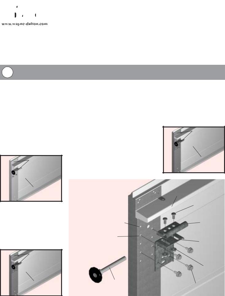
Top Bracket Installation |
To install the L-shaped top brackets, align the top holes in the top bracket with the first set of holes in the endcap for 9900 Thermowayne™ doors and second set of holes for 9600 Thermogard ® doors and 9200/9100 Foamcore™ doors. Fasten using (4) 1/4-20 x 5/8” self tapping screws. Secure the top bracket slide to the bracket using
(2) 1/4-20 x 5/8” carriage bolts and nuts. Insert rollers. (see Fig. 1)
NOTE: To differentiate between a 9900 Thermowayne™, 9600 Thermogard® and 9200/9100 Foamcore™ door models, look for the following characteristics:
1) 9900 Thermowayne™
(below) will have painted hardware (top brackets, bottom brackets, end caps, etc.) with a steel backing on the sections.
PAINTED
HARDWARE
STEEL BACKING
3) 9200/9100 Foamcore™
(below) will have galvanized hardware, with a laminated (soft) backing on the sections.
GALVANIZED
HARDWARE
LAMINATED (SOFT) BACKING
2) 9600 Thermogard® (right) will have galvanized hardware, with a steel backing on the sections.
GALVANIZED HARDWARE
STEEL
BACKING
|
|
|
|
|
|
|
|
TOP SECTION |
|
|
|
|
RIB |
|
|
|
|
(2) CARRIAGE |
|
|
|
|
BOLTS |
|
|
1ST SET OF HOLES ON |
TOP |
|
|
|
9900 THERMOWAYNE™ |
|
||
|
|
|
BRACKET |
|
|
2ND SET OF HOLES ON |
SLIDE |
|
|
|
|
|
||
|
9600 THERMOGARD® |
TOP |
|
|
|
AND |
BRACKET |
|
|
|
9200/9100 FOAMCORE™ |
|
|
|
|
|
|
(2) HEX |
|
|
|
|
NUTS |
|
|
ROLLER |
|
|
|
|
|
|
(4) SELF-TAPPING |
|
|
|
FIG. 1 |
SCREWS |
|
|
|
|
|
|
2

The idrive™ garage door opener is best installed in combination with the door installation steps. Refer to this idrive™ installation insert when you reach Step 12 TorqueMaster™ installation, in the main door installation instructions and owners manual. When instructed to slide the center bracket/bushing onto the torque tube, replace that step with the following instructions below, which will provide the steps necessary to install the TorqueMaster™ system, as well as the preliminary installation steps for the idrive™ garage door opener.
12 |
Power Head Assembly |
Lay the torque tube on the floor (inside garage) in front of the door with the labeled end to the left. NOTE:
Opener will not slide over a torque tube label.
Attempting to slide opener over the left end of the torque tube can damage the internal electronics.
NOTE: Hold opener by the main body. Do NOT hold by the motor.
Look into the opener’s left side to ensure the left hand bearing and the internal (black) sleeve are aligned with the torque tube profile. Once aligned, slide the opener power head onto the right hand end of the torque tube. As the right end of the torque tube enters the internal (black) sleeve, rotate the opener back and forth slightly to help aid alignment.
NOTE: Do not force the opener onto the torque tube if misalignment occurs.
OPENER POWER HEAD
TORQUE TUBE AND
BEARINGS PROFILES
ALIGNED
FIG. 2
Continue sliding the opener power head onto the torque tube. Align the right hand bearing with the torque tube and slide the opener power head completely onto the torque tube until the torque tube exits the opener power head’s right hand bearing. Continue sliding the opener power head to the center of the torque tube and plug the motor into the opener power head.
IMPORTANT! Right and left hand are always determined from inside the garage looking out.
OPENER POWER
HEAD
LEFT HAND |
FIG. 3 |
BEARING |
OPENER
POWER
HEAD
|
RIGHT HAND |
|
FIG. 4 |
||
BEARING |
||
|
PLUG MOTOR
INTO THE OPENER
POWER HEAD
LABEL (LEFT SIDE)
SLIDE OPENER POWER HEAD
TORQUE TUBE
TORQUE TUBE
MOTOR
INSERT THIS END FROM LEFT SIDE OF OPENER
3
 Loading...