


Wayne-Dalton Corp.
P.O. Box 67 Mt. Hope, OH 44660
(888) 827-3667
www.wayne-dalton.com
Photoelectric Safety Sensors
Installation Instructions
and Owner’s Manual
Opener Models:
Torsion idrive™ models: 3651-372, 3750-372.
Quantum™/Classicdrive™ models: 3012, 3014, 3016, 3018, 3212, 3213, 3214, 3312, 3313, 3314, 3316, 3412, 3414, 3512, 3514. DoorMaster™ models: BDOR-2000 & BIRW-2000
idrive™ models: 3660-372, 3661-372, 3662-372, 3760-372, 3751-372.
WIRES ARE
PRE-ATTACHED
|
Photoelectric Sensors Hardware: 297218 |
|
|
(2) 5/16 x 1-1/2” Lag Screws |
|
|
(2) 1” Flat Head Nails |
|
Photoelectric Sensors |
(2) 1/4-20 x 1/2” Carriage Bolts, Washers & Nuts |
|
(1) Sender w/Wire: 260600 |
(2) Wall Mounting Brackets |
|
(2) “U” Brackets |
||
(1) Receiver w/Wire: 260597 |
||
(1) Power Cord Clip (adhesive back) |
||
|
||
|
(1) Jumper |
Important Notice!
DOOR OPENER WILL NOT OPERATE PROPERLY UNTIL PHOTOELECTRIC SENSORS ARE INSTALLED AND PROPERLY ADJUSTED! DO NOT OPERATE DOOR OPENER UNTIL IT IS FULLY INSTALLED, ADJUSTED AND YOU ARE INSTRUCTED TO DO SO!
© Copyright 2003 Wayne-Dalton Corp. |
Part No: 306736 |
New |
9/4/2003 |
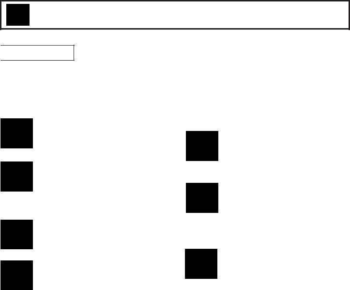
Table of Contents
Important Safety Instructions For Installation And Use |
2. |
Bracket Installation |
3. |
Wiring Installation “Quantum™/Classicdrive™” |
4. |
Wiring Installation “DoorMaster™” |
4. |
Wiring Installation “idrive™” |
5. |
Wiring Installation “Torsion idrive™” |
5. |
Photoelectric Safety Sensor Alignment |
6. |
Photoelectric Obstruction Sensing Test |
6. |
Important Safety Instructions |
7. |
Warranty |
7. |
Customer Service Number |
7. |
THIS IS THE SAFETY ALERT SYMBOL. IT IS USED TO ALERT YOU TO POTENTIAL PERSONAL INJURY HAZARDS. OBEY ALL SAFETY MESSAGES THAT FOLLOW THIS SYMBOL TO AVOID POSSIBLE INJURY OR DEATH.
 WARNING DISCONNECTALL POWER FROM GARAGE DOOR OPENER BEFORE SERVICING OR INSTALLING ACCESSORY PRODUCTS.
IMPORTANT SAFETY INSTRUCTIONS FOR
INSTALLATION AND USE
READ AND FOLLOW ALL INSTALLATION INSTRUCTIONS.
DO NOT USE SENSITIVITY ADJUSTMENT TO COMPENSATE FOR A POORLY OPERATING DOOR. THIS WILL INTERFERE WITH THE PROPER OPERATION OF THE SAFETY REVERSE MECHANISM.
DO NOT CONNECT OPENER TO ELECTRICAL OUTLET UNTIL INSTRUCTED TO DO SO.
INSTALLATION AND WIRING MUST COMPLY WITH LOCAL BUILDING AND ELECTRICAL CODES. CONNECT THE POWER CORD TO A PROPERLY GROUNDED OUTLET. DO NOT REMOVE ROUND GROUND PIN FROM POWER CORD.
AFTER INSTALLING OPENER, THE DOOR MUST REVERSE WHEN IT CONTACTS A 1 INCH HIGH SOLID TEST OBJECT ON THE FLOOR.
OPEN DOOR MUST NOT CLOSE AND CLOSING DOOR MUST OPEN IF PHOTOELECTRIC SYSTEM IS OBSTRUCTED BY 6”X HIGH OBJECT, USING TEST PROCEDURE DESCRIBED IN STEP 4.
DO NOT WEAR RINGS, WATCHES OR LOOSE CLOTHING WHEN INSTALLING OR SERVICING A GARAGE DOOR SYSTEM. USE A STURDY, NONMETALLIC STEP LADDER AND WEAR EYE PROTECTION.
2
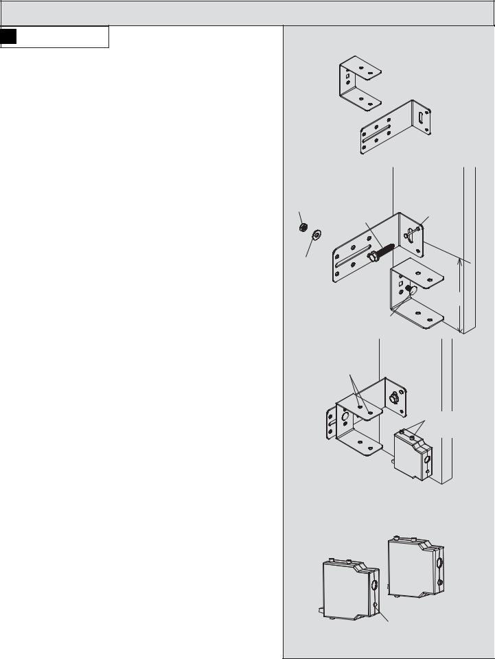
Step 1: Photoelectric Safety Sensor Bracket Installation
WARNING DISCONNECT ALL POWER TO |
|
“U” BRACKETS |
|
GARAGE DOOR OPENER BEFORE SERVICING OR |
|
|
|
|
|
|
|
INSTALLING ACCESSORIES OR PHOTOELECTRIC |
|
|
|
SAFETY SENSORS. FOR ALL OPENERS, UNPLUG 120 V |
|
|
|
AC POWER CORD FROM RECEPTACLE. FOR |
|
|
|
DOORMASTER,ALSO UNPLUG TELEPHONE CORD TYPE |
|
|
|
COMMUNICATIONS CABLE. |
|
|
|
Select a mounting position, no more than 5 inches above the |
|
|
WALL MOUNTING |
floor to center line of wall mounting bracket. The sending and |
|
|
BRACKETS |
receiving units should be mounted inside the door opening to |
|
|
|
minimize any interference by the sun. However, the sensors |
|
|
|
should be mounted as close to the door track or inside edge of |
NUT |
(1) 5/16 X 1-1/2” |
|
the door as possible to offer maximum entrapment protection. |
|||
It is very important that both wall brackets be mounted at the |
|
LAG SCREW |
NAIL |
|
|
|
|
same height for proper alignment. |
|
|
|
The brackets may be temporarily mounted to the jamb with a 1” WASHER |
|
||
flat head nail (provided) using the small hole above the slot. |
|
|
|
Using two 5/16 x 1-1/2” lag screws (provided), permanently |
|
|
5” |
mount the wall mounting brackets to both door jambs. In some |
|
|
|
installations it may be necessary to attach a wooden spacer to |
|
(1)1/4-20 X 1/2” |
|
the wall to achieve the required clearance. |
|
CARRIAGE BOLT |
|
Attach the “U” brackets to the wall brackets with a |
|
TAB HOLES |
|
1/4-20 carriage bolt, washer and nut (provided). Insert |
|
|
|
|
TOP & BOTTOM |
|
|
the bolt from the inside of the “U” bracket and hand tighten only |
|
|
|
|
|
|
|
at this time. |
|
|
|
Identify which side of the garage door opening (if any) is “likely” |
|
|
TABS |
to be exposed to sunlight. Since sunlight may affect photoelectric |
|
|
TOP & BOTTOM |
sensors, you should mount the sending unit (not the receiving |
|
|
|
unit) on the side of the door opening exposed most to the sun. |
|
|
|
NOTE: If wires must be lengthened or spliced into prewired |
|
|
|
installation, use wire nuts or suitable connectors. |
|
|
|
Attach the sending and receiving units to the “U” brackets by |
|
|
|
inserting their tabs into the respective holes. |
|
|
|
|
RECEIVING UNIT |
|
|
|
|
|
SENDING |
|
|
|
UNIT |
|
|
|
(NO LED) |
|
|
|
LED ALIGNMENT |
|
|
|
LIGHT |
3 |
|
|
|
 Loading...