


 Loading...
OWNER’S MANUAL
Safety, Assembly, Operating, and Maintenance Instructions
Model MT (20.0 / 25.0 HP) (Covers Serial Numbers 95-21329 and on)
™
Please Read and Save These Instructions |
Effective Date: 08-14-98 |
For Safety, Read All Safety and Operation |
P/N 8000-1 |
Instructions Prior to Operating Machine |
Price $5.00 |

Foreword
Thank you. . .for purchasing a Walker mower. Every effort has been made to provide you with the most reliable mower on the market, and we are sure you will be among our many satisfied customers. If for any reason this product does not perform to your expectations, please contact us at (970) 221-5614. Every customer is important to us. Your satisfaction is our goal.
Please. . .read this manual thoroughly! This manual is to be used in conjunction with the engine manufacturer’s manual for the specific engine on the mower model you have purchased. Before you operate your new mower, please read this entire manual. Some of the information is crucial for proper operation and maintenance of this mower - it will help protect your investment and ensure that the mower performs to your satisfaction. Some of the information is important to your safety and must be read and understood to help prevent possible injury to the operator or others. If anything in this manual is confusing or hard to understand, please call our service department, at (970) 221-5614, for clarification before operating or servicing this mower.
This manual covers Model MT with the Kohler Command CH20 (20.0 HP) gasoline engine, or optional Kohler Command CH25 (25.0 HP) gasoline engine.
All shields and guards must be in place for the proper and safe operation of this machine.
Where they are shown removed in this manual, it is for illustration purposes only. Do not operate this machine unless all shields and guards are in place.
Specifications given are based on the latest information available at the time this manual was produced.
Walker Mfg. Co. is continually striving to improve the design and performance of its products. We reserve the right to make changes in specifications and design without thereby incurring any obligation relative to previously manufactured products.
Sincerely,
WALKER MANUFACTURING COMPANY
Bob Walker, President

Table of Contents
General Information ________________ 1
HIGHLIGHTED INFORMATION _____________ 1
GLOSSARY ____________________________ 1
IDENTIFYING NUMBER LOCATIONS ________ 1 ENGINE SERIAL NUMBER LOCATION ______ 2
SERVICING OF ENGINE
AND DRIVETRAIN COMPONENTS__________ 2
Specifications _______________________ 3
ENGINE________________________________ 3 ELECTRICAL SYSTEM ___________________ 3 TRANSMISSION _________________________ 3 BLADE DRIVE __________________________ 4 TIRE SIZE ______________________________ 4 TIRE PRESSURE ________________________ 5
DIMENSIONS (Tractor and Mower) _________ 5
MOWER DECK __________________________ 5 CURB WEIGHT__________________________ 5 DRIVE BELTS ___________________________ 6
GHS SYSTEM (Optional) __________________ 6
SEAT __________________________________ 6
FRAME/BODY CONSTRUCTION ___________ 6
Component Identification___________ 7
Safety Instructions _________________ 10
BEFORE OPERATING ___________________ 10 OPERATING ___________________________ 11 MAINTENANCE ________________________ 12
SAFETY, CONTROL,
AND INSTRUCTION DECALS _____________ 14
Assembly Instructions _____________ 16
SETUP INSTRUCTIONS _________________ 16
Tire Installation (Tractor) _______________ 16
Battery Service _______________________ 16 Wet Battery Service __________________ 16 Dry Battery Service ___________________ 16 Battery Charging _____________________ 17 Battery Installation ___________________ 17
Mower Deck Assembly ________________ 17
Deck Caster Wheels Installation _________ 17 Deck Discharge Chute Installation _______ 18 Deck Discharge Shield Installation _______ 18 PTO Shaft Guard Installation ___________ 18
Mower Deck Installation on Tractor ______ 18
Deck Installation _____________________ 18 Deck Leveling _______________________ 20
PREOPERATING CHECKLIST ____________ 21
Operating Instructions_____________ 24
CONTROL IDENTIFICATION,
LOCATION, AND FUNCTION _____________ 24
Operating Controls ___________________ 24 Engine Choke _______________________ 24 Engine Throttle ______________________ 25
Forward Speed Control (FSC) __________ 25
Steering Levers _____________________ 25 Blade Clutch (PTO) __________________ 25 Parking Brake _______________________ 25
Front Body Latch Release _____________ 26 Transmission Lockout Levers ___________ 26 Cold Start Lever (Jackshaft Drive Belt Release)_ 26
Instrument Panel _____________________ 28 Hourmeter _________________________ 29 Voltmeter __________________________ 29
Oil Pressure Warning Light ____________ 29 Over Temperature Warning Light ________ 29
Ignition Switch ______________________ 29
Light Switch (For Optional Lights) _______ 29
Warning Horn _______________________ 29 STARTING THE ENGINE_________________ 30
ADJUSTING GROUND
SPEED AND STEERING _________________ 31 ENGAGING THE MOWER ________________ 32
STOPPING THE MACHINE _______________ 33 ADJUSTING CUTTING HEIGHT ___________ 34 TRANSMISSION LOCKOUT ______________ 34 RECOMMENDATIONS FOR MOWING ______ 35
RECOMMENDATIONS FOR TILT-UP DECK OPERATION/TRANSPORT _______________ 36 GRASS HANDLING SYSTEM (GHS) _______ 37
General Information __________________ 38 Clogging Checklist ___________________ 39
Using the Tilt-Up Deck ________________ 40 Using the GHS Catcher ________________ 40
Powerfil ®__________________________ 40 “Full” Signal Horn ____________________ 40
Cleaning the GHS Exhaust Screen ______ 40
Dumping the Catcher _________________ 41 Tailgate Dumping ____________________ 41 Using the Dump Bag _________________ 41 Power Dump Option __________________ 42

Table of Contents
Maintenance Instructions __________ 44
MAINTENANCE SCHEDULE CHART _______ 44
IMPORTANT TIPS
FOR CARE OF THE KOHLER ENGINE _____ 45
Fuel System _________________________ 45 Starting/Stopping _____________________ 45 Cooling System ______________________ 45 Air Cleaner System ___________________ 45 Oil _________________________________ 45
LUBRICATION _________________________ 46 Engine Oil ___________________________ 46 Engine Break-In Oil___________________ 46
Checking Engine Crankcase Oil Level ____ 46 Changing Engine Crankcase Oil/Oil Filter _ 46
Grease Fitting and Oil Point Lubrication __ 47 Mower Deck Gearbox Lubrication _______ 50 DSD52 or DSD62 Mower Deck Lubrication 50 Tractor PTO Gearbox Lubrication _______ 51
Checking Gearbox Oil Level ____________ 51 Changing Gearbox Oil ________________ 51
Gear Axle Lubrication _________________ 51 Hydrostatic Transmission Fluid _________ 52
Checking Hydrostatic
Transmission Fluid Level ______________ 52 Changing Hydrostatic Transmission Fluid__ 52
CLEANING ____________________________ 53
Engine Air Cleaner System _____________ 53
Turbine Precleaner ___________________ 54
Donaldson Radialseal™
Air Cleaner (Primary) _________________ 54 Kohler Air Cleaner (Secondary) _________ 56
Foam Precleaner __________________ 56 Paper Element ____________________ 56
Engine Cooling System ________________ 57
Air Intake System ____________________ 57
Cylinder Head Cooling Fins ____________ 57
Grass Buildup in Mower Housing________ 58
Non-Tilting Decks ____________________ 58 Tilt-Up Decks _______________________ 58 GHS Blower _________________________ 59 GHS Exhaust Screen __________________ 59
Hydrostatic Transmission Cooling Fins __ 60
CHECKING/SERVICING _________________ 60
Security of Air Filtration Components ____ 60
Battery______________________________ 60 Electrolyte Level _____________________ 60
Cleaning the Terminals ________________ 61
Charging the Battery __________________ 61 Tire Pressure ________________________ 61
Sharpen Mower Blades ________________ 61
Drive Belts __________________________ 62
Mower Deck Gearbox Oil Seals _________ 63
Spark Plugs _________________________ 63
Fuel Lines and Clamps ________________ 63
Engine Starter _______________________ 63 Blade Brake Action ___________________ 63
REPLACING/REPAIRING ________________ 63
Drive Belts __________________________ 63
Engine PTO Drive Belt ________________ 65
Jackshaft Drive Belt __________________ 66
GHS Blower Drive Belt ________________ 67 Hydrostatic Ground Drive Belt __________ 68
Fuel Filter ___________________________ 69
Blade Overload Shear Bolts ____________ 69
Mower Blades _______________________ 70
Mower Deck Gearbox Replacement______ 70
GHS Blower Assembly ________________ 71
GHS Blower Assembly Removal ________ 71 Blower Wheel Removal _______________ 72 Blower Wheel Installation ______________ 72 GHS Blower Assembly Installation _______ 72
ADJUSTMENTS ________________________ 73 Safety Switches ______________________ 73 Seat Switch ________________________ 73
FSC Neutral-Park Switch ______________ 73
PTO Switch_________________________ 73
Tail Wheel Bearing Preload_____________ 73
Blade Clutch (PTO) ___________________ 74
Clutch Engagement/Belt Tension ________ 74 Clutch Disengagement/Brake Action _____ 75 Stop Block Eccentric Adjustment ________ 76 Clutch Idler Pulley Travel Adjustment_____ 76 Blade Brake Band Adjustment __________ 76
Transmission Control _________________ 77
Set Forward Travel Limit (Stop) _________ 77 Steering Lever End Play Adjustment _____ 78 Neutral Function Adjustment ___________ 78 Straight Ground Travel Adjustment ______ 79
Forward Speed Control Friction Lock ____ 79 Tilt-Up Deck Adjustable Stop ___________ 80
Carburetor __________________________ 80
Engine Idle Adjustment _______________ 80
GHS “Full” Signal Horn
with Grass-Pak® Switch _______________ 81
Troubleshooting
(When Horn Fails to Operate) __________ 81 Adjustment
(When Horn Sounds at the Wrong Time) __ 82
ELECTRICAL SYSTEM __________________ 82 Circuit Breakers______________________ 82 Wiring Diagram ______________________ 83
Operator’s Notes ___________________ 84
Warranty___________________________ 87

General Information
HIGHLIGHTED INFORMATION
Walker Manufacturing recommends that any service requiring special training or tools be performed by an authorized Walker Mower Dealer. There are several general practices to be aware of in the area of safety. Most accidents associated with the operation or maintenance of a Walker Mower are caused by disregarding basic safety precautions or specific warnings. Such accidents, in most cases, can be prevented by being aware of the dangers present.
Information of special importance has been highlighted in bold type in this manual. Refer to Safety Instructions for the meanings of DANGER, WARNING, CAUTION, IMPORTANT, and NOTE.
GLOSSARY
There are many terms that are either unique to this equipment or that are used as acronyms. The following terms and their definitions will help while using this manual:
∙DECK is the mowing attachment mounted on the front of the tractor which includes the carrier frame, deck housing, blade drive gearboxes, and cutter blades.
∙FORWARD SPEED CONTROL (FSC) controls the maximum forward speed of the tractor; functioning as a cruise control.
∙GRASS HANDLING SYSTEM (GHSâ) collects mowed material and deposits it in the catcher.
∙GRASS-PAKâ SWITCH is mounted on the grass delivery spout (in the catcher) and activates the “full” signal horn when the grass catcher is full.
∙GROUND DRIVE refers to the dual hydrostatic transmissions which drive the main wheels.
∙HYDROSTATIC TRANSMISSION transmits and controls power from the ground drive belt to the main drive wheel.
∙LEFT HAND (LH) refers to the left-hand side of the tractor when the operator is seated facing forward in the tractor seat.
∙POWER TAKE-OFF (PTO) transmits engine power to run the cutter blades and GHS blower.
∙POWERFILâ spreads the mowed material throughout the interior of the grass catcher by an oscillating delivery spout.
∙RIGHT HAND (RH) refers to the right-hand side of the tractor when the operator is seated facing forward in the tractor seat.
∙SIDE DISCHARGE (SD) mows but does not collect the mowed material.
∙STEERING LEVERS steer the tractor by controlling the dual hydrostatic transmissions.
∙TRACTOR is the prime mover, including the engine, drive train, operator seat, and controls to operate the mower.
∙TRANSMISSION LOCKOUT releases the hydrostatic transmissions to permit freewheeling the tractor.
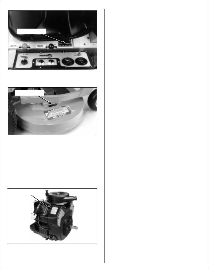
IDENTIFYING NUMBER LOCATIONS
The tractor serial number plate is affixed to the tractor body just below the left rear corner of the seat. The mower deck serial number plate is affixed alongside the angle iron framing on the RH side of the RH mower blade drive. Model and serial numbers are helpful when obtaining replacement parts and maintenance assistance. For ready reference, please record these numbers in the space provided.
Tractor Model No. _______________________
Tractor Serial No. _______________________
Deck Serial No. _______________________
Engine Model No. _______________________
Engine Serial No. _______________________
Date of Purchase _______________________
Fill In By Purchaser
1
General Information
Serial Number
Tractor Serial Number Location
Serial Number
Mower Deck Serial Number Location
ENGINE SERIAL NUMBER LOCATION
Refer to the engine manual that accompanies this manual for the location of the engine serial number. For the mower model covered by this manual, an engine manual is available covering the Kohler CH20 and CH25 gasoline engines.
Serial Number
Engine Serial Number Location
SERVICING OF ENGINE AND DRIVETRAIN COMPONENTS
The detailed servicing and repair of the engine, hydrostatic transmission, and gearboxes are not covered in this manual. Only routine maintenance and general service instructions are provided. For the service of these components during the limited warranty period, it is important to find a local, authorized servicing agent of the component manufacturer.
Any unauthorized work done on these components during the warranty period may void the warranty. If you have any difficulty finding an authorized outlet or obtaining warranty service, please contact our Service Department for assistance:
Walker Manufacturing Company
5925 E. Harmony Road
Fort Collins, CO 80528
1-970-221-5614
Service manuals are available for each of these components from their respective manufacturers as follows:
Kohler Engines |
Kohler Company |
|
Kohler, WI 53044 |
Hydrostatic |
Eaton Corporation |
Transmissions |
15151 Highway 5 |
|
Eden Prairie, MN 55344 |
Gearboxes (Deck) |
Tecumseh Products Co. |
|
900 North Street |
|
Grafton, Wl 53024 |
2

Specifications
MODEL |
MT 20.0 HP |
MT 25.0 HP |
|
|
|
ENGINE
Manufacturer/Model
Displacement
HP (@ 3600 RPM) Max. RPM (No Load) Governed RPM
Max. Torque [ft-lb (N×m) @ RPM] Idle RPM
Spark Plug Type
Spark Plug Gap
Crankcase Capacity
Crankcase Lubricant
Fuel Tank Capacity
Fuel
Cooling System Capacity
Kohler CH20, 2 Cyl.,
Gasoline (Air Cooled)
38.1 cu. in. (624 cc)
20.0
3750
3600
32 (43.4) @ 2500
1200 ± 75 Championâ RC12YC
.030 in. (.76 mm)
2.1 qts (2.0 liters)
API SF, SG, or SH Grade Oil Only with 10W-30 Viscosity above 0° F (-18° C), or 5W-20 or 5W-30 Viscosity below 32° F (0° C)
4.3 Gallons (16.3 liters)
Regular Grade Unleaded
Gasoline (87 Octane)
Air Cooled
Kohler CH25, 2 Cyl.,
Gasoline (Air Cooled)
44.0cu. in. (725 cc)
3750
3600
39.5(53.6) @ 2400
1200 ± 75 Championâ RC12YC
.030 in. (.76 mm)
2.1qts (2.0 liters)
API SF, SG, or SH Grade Oil Only with 10W-30 Viscosity above 0° F (-18° C), or 5W-20 or 5W-30 Viscosity below 32° F (0° C)
4.3 Gallons (16.3 liters)
Regular Grade Unleaded
Gasoline (87 Octane)
Air Cooled
ELECTRICAL SYSTEM
Battery |
12 Volt, 35AH, 295 CCA |
Charging System |
Flywheel Alternator |
Charging Output |
15 Amp DC (Regulated) |
System Polarity |
Negative Ground |
Ignition |
Electronic Capacitive |
|
Discharge |
Starter |
12 Volt Electric Ring-Gear |
|
Type, Solenoid Shift |
Interlock Switch |
Ignition Lockout by Seat |
|
Switch, Transmission Neutral |
|
and Blade Clutch |
Circuit Breaker |
Manual Reset (30A) |
12 Volt, 35AH, 295 CCA
Flywheel Alternator
15 Amp DC (Regulated)
Negative Ground
Electronic Capacitive
Discharge
12 Volt Electric Ring-Gear
Type, Solenoid Shift
Ignition Lockout by Seat Switch, Transmission Neutral and Blade Clutch
Manual Reset (30A)
TRANSMISSION |
|
Manufacturer/Model |
Dual Hydrostatic, Eaton |
|
Model 7, Each Wheel |
|
Independently Driven |
Steering |
Hand Lever Control / |
|
Individual Wheel |
Forward Speed Control |
Precision Friction Lock Lever, |
|
Cruise Control, with |
|
Neutral-Park Position |
Dual Hydrostatic, Eaton
Model 7, Each Wheel
Independently Driven
Hand Lever Control /
Individual Wheel
Precision Friction Lock Lever, Cruise Control, with Neutral-Park Position
3

Specifications
MODEL |
MT 20.0 HP |
MT 25.0 HP |
||
|
|
|
|
|
TRANSMISSION (continued) |
|
|
|
|
Service Brake |
Dynamic Braking through |
Dynamic Braking through |
||
|
Hydrostatic Transmission |
Hydrostatic Transmission |
||
Parking Brake |
Mechanical Pin Lock in |
Mechanical Pin Lock in |
||
|
Transmission Gear |
Transmission Gear |
||
Neutral |
Transmission Release by |
Transmission Release by |
||
|
Manual Dump Valve |
Manual Dump Valve |
||
Final Drive |
Gear Drive Axle |
Gear Drive Axle |
||
Transmission Fluid |
|
|
|
|
Factory Service |
SAE 30W Straight Viscosity |
SAE 30W Straight Viscosity |
||
|
Motor Oil (Mobil DTE 18M |
Motor Oil (Mobil DTE 18M |
||
|
Hydraulic Oil Installed at |
Hydraulic Oil Installed at |
||
|
Factory) |
|
Factory) |
|
Alternate Transmission Fluid |
Mobil 1 Synthetic Motor Oil |
Mobil 1 Synthetic Motor Oil |
||
|
(5W30) |
|
(5W30) |
|
Transmission Fluid Capacity |
1 qt (1 liter) |
1 qt (1 liter) |
||
Transmission Cooling |
Cooling Fan Mounted on |
Cooling Fan Mounted on |
||
|
Drive Pulley |
Drive Pulley |
||
Ground Travel Speed |
|
|
|
|
Forward m.p.h. (km/h) |
0-5 (0-8) |
Infinitely Variable |
0-5 (0-8) |
Infinitely Variable |
Reverse m.p.h. (km/h) |
0-5 (0-8) |
Infinitely Variable |
0-5 (0-8) |
Infinitely Variable |
BLADE DRIVE
PTO Shaft
Blade Spindle
Blade Drive Clutch and Brake
Max. Blade Speed [25 in. (64 cm) Blade] @ 3600 RPM Engine
Quick Disconnect Rectangular Shaft with Two High-Speed U-Joints
Each Blade (2) Mounts Direct on Peerless Right Angle Gearbox with Tee Gearbox in Center Connected to PTO Shaft (Complete Geared Drive, Peerless Model 1000 Gearboxes)
Manual Belt Tightener Clutch and Band Brake (Stops Blades within Five (5) Seconds of Disengagement)
2400 RPM
[15700 FPM (4785 m/min)]
TIRE SIZE |
|
|
Deck Caster Wheel |
2.80/2.50-4 Pneumatic (4-Ply) |
2.80/2.50-4 Pneumatic (4-Ply) |
Deck Caster Wheel (Optional) |
8.25 x 2.75 Semi-Pneumatic |
8.25 x 2.75 Semi-Pneumatic |
Drive |
18 x 9.50-8 (4-Ply) |
18 x 9.50-8 (4-Ply) |
Rear (Dual) |
13 x 5.00-6 (4-Ply) |
13 x 5.00-6 (4-Ply) |
|
|
|
4

Specifications
MODEL |
MT 20.0 HP |
MT 25.0 HP |
|
|
|
TIRE PRESSURE |
|
|
Deck Caster Wheel |
20 PSI (137 kPa) |
20 PSI (137 kPa) |
Drive |
15 PSI (103 kPa) |
15 PSI (103 kPa) |
Rear |
20 PSI (137 kPa) |
20 PSI (137 kPa) |
|
|
|
DIMENSIONS (Tractor and Mower)* |
|
|
Length |
91 in. (231 cm) |
91 in. (231 cm) |
Width |
49 in. (124 cm) |
49 in. (124 cm) |
Height |
44 in. (112 cm) |
44 in. (112 cm) |
Wheel Base (Tractor) |
42-1/4 in. (107 cm) |
42-1/4 in. (107 cm) |
Tread Width (Tractor) |
29-3/4 in. (76 cm) |
29-3/4 in. (76 cm) |
|
|
|
MOWER DECK |
|
|
Width of Cut SD/GHS |
42 or 48 in. (107 or 122 cm) |
Cutting Height |
1 to 4 in. (3 to 10 cm) |
Height Adjustment |
7 Positions - 1/2 in. (1 cm) |
|
Increment Hitch Pins Installed |
|
in Multi-Position Deck Support |
Blade Size (Typical) |
|
42 or 48 in. (107 or 122 cm)
1 to 4 in. (3 to 10 cm)
7 Positions - 1/2 in. (1 cm) Increment Hitch Pins Installed in Multi-Position Deck Support
42 in. (107 cm) SD |
22 in. (56 cm) |
|
2 in. (5 cm) Center Overlap |
|
(Two Blades, CW Rotation) |
48 in. (122 cm) GHS |
25 in. (64 cm) |
|
2 in. (5 cm) Center Overlap |
|
(Two Blades, Counter Rotate) |
Deck Suspension |
Torsion-Flex Frame with |
|
Caster Wheels and |
|
Counterweight Springs |
22 in. (56 cm)
2 in. (5 cm) Center Overlap (Two Blades, CW Rotation)
25 in. (64 cm)
2 in. (5 cm) Center Overlap (Two Blades, Counter Rotate)
Torsion-Flex Frame with Caster Wheels and Counterweight Springs
CURB WEIGHT (Approximate) |
|
|
SD Tractor Only |
660 lb (299 kg) |
665 lb (302 kg) |
GHS Tractor Only |
760 lb (345 kg) |
765 lb (347 kg) |
Tractor and Mower* |
965 lb (438 kg) |
970 lb (440 kg) |
|
|
|
*Dimensions and weight shown are for 48 in. (122 cm) GHS Model (typical). Dimensions for Tractor and Mower with 42 in. (107 cm) deck are:
Length = 88 in. (224 cm) Width = 43 in. (110 cm)
For SD Models, subtract 7 in. (18 cm) from the height.
Deck weight for 48 in. (122 cm) Tilt-Up deck = 205 lb (93 kg). Deck sizes range from 42 to 62 in. (107 to 157 cm), with corresponding deck weights ranging from 170 to 300 lb (77 to 136 kg). Optional (9.5 Bushel) Grass Catcher adds approx. 5 lb (2 kg) and 5 in. (13 cm) in Height
5

Specifications
MODEL |
MT 20.0 HP |
MT 25.0 HP |
|
|
|
DRIVE BELTS |
|
|
Engine PTO |
Walker P/N 8230 |
Walker P/N 8230 |
Jackshaft Drive |
Gates 3VX355 |
Gates 3VX355 |
|
(or Walker P/N 6231) |
(or Walker P/N 6231) |
Ground Drive, Micro-V |
Walker P/N 7248 |
Walker P/N 7248 |
Blower (GHS Model) |
Gates 3VX280 |
Gates 3VX280 |
|
(or Walker P/N 7234) |
(or Walker P/N 7234) |
|
|
|
GHS SYSTEM (Optional) |
|
|
Blower |
4 x 10 x 1/4 in. (10 x 25 x 1 cm) |
4 x 10 x 1/4 in. (10 x 25 x 1 cm) |
|
Three-Blade Paddle Wheel |
Three-Blade Paddle Wheel |
|
(Driven by Mower Engine) |
(Driven by Mower Engine) |
Blower Brake |
Band Brake (Works in Combi- |
Band Brake (Works in Combi- |
|
nation with PTO Clutch, Stops |
nation with PTO Clutch, Stops |
|
Blower within Five (5) Seconds |
Blower within Five (5) Seconds |
|
of PTO Disengagement) |
of PTO Disengagement) |
Max. Blower Speed |
3600 RPM |
3600 RPM |
Grass Catcher Capacity |
65 Gallons (246 liters)/ |
65 Gallons (246 liters)/ |
|
7.0 Bushels |
7.0 Bushels |
Optional Grass Catcher |
76 Gallons (335 liters)/ |
76 Gallons (335 liters)/ |
Capacity |
9.5 Bushels |
9.5 Bushels |
Full Signal |
Oscillating Vane Switch |
Oscillating Vane Switch |
|
Mounted on Grass Delivery |
Mounted on Grass Delivery |
|
Spout Triggers Horn Signal |
Spout Triggers Horn Signal |
Powerfil ® |
Oscillating Delivery Spout |
Oscillating Delivery Spout |
|
Driven by 12 Volt Electric |
Driven by 12 Volt Electric |
|
Gearmotor Spreads Material |
Gearmotor Spreads Material |
|
throughout Interior of Catcher |
throughout Interior of Catcher |
|
@ 25 Cycles/Minute |
@ 25 Cycles/Minute |
|
|
|
SEAT |
Contour-Molded, with Nylon |
Contour-Molded, with Nylon |
|
Backed Vinyl Cover and |
Backed Vinyl Cover and |
|
Integral Foam Cushion |
Integral Foam Cushion |
|
|
|
FRAME/BODY CONSTRUCTION |
|
|
Frame |
All Welded Unitized Steel |
All Welded Unitized Steel |
|
Chassis |
Chassis |
Body |
14 Gauge Steel |
14 Gauge Steel |
Deck |
11 Gauge Steel |
11 Gauge Steel |
GHS Catcher and Chutes |
Molded Cross-Linked |
Molded Cross-Linked |
|
Polyethylene (UV Stabilized) |
Polyethylene (UV Stabilized) |
|
|
|
NOTE: The manufacturer reserves the right to make changes in specifications shown herein at any time without notice or obligation.
6
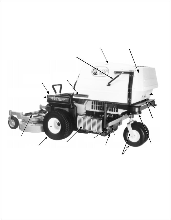
Component Identification
|
|
|
NOTE: Control Identification |
|
|
|
shown in Operating |
|
|
|
Instructions section. |
Catcher Door |
Turbine |
Grass Handling System |
|
Precleaner |
|
||
Safety Latch |
7.0 Bushel Catcher |
|
|
|
|
||
|
|
Tilt-Up |
Spring Clip |
|
|
Latch |
|
|
|
|
|
|
|
|
Transmission Control Rod |
|
|
|
Adjustment Nut (LH) |
Anti-Scuff |
|
|
|
Roller |
|
|
|
|
|
|
Deck Support Pins |
Catcher Lift / |
|
|
and Height Adjustment |
Dump Handle |
|
|
Hitch Pins |
Fuel Tank |
|
|
|
and Cap |
|
|
|
Counterweight Spring |
|
|
|
and Protective Cover |
|
|
|
Transmission Control Rod |
|
|
|
Adjustment Nut (RH) |
|
|
|
|
Deck Support Arms |
|
|
|
Deck Lift Handle |
|
Footrests |
(Cutting Height Adjustment) |
|
||
|
|
Tilt-Up Hook |
|
|
|
Tilt-Up |
|
|
|
Deck Handle |
|
|
|
|
Deck |
|
|
|
Caster Wheels |
|
|
Front View and Right Side View |
|
7
Component Identification
Catcher Door
Gas Spring
Catcher Lift /
Instrument Panel Dump Handle
Guard
Instrument Panel Box
(Shock Mounted) 
Deck Lift Rod
Muffler
Left Hand
Drive Wheel
Removable Grass |
|
|
|
Catcher Exhaust |
|
Catcher Screen |
|
|
(Not Visible) |
|
Deflector |
|
|
|
Catcher
Door
Dump
Plate
Catcher
Door Handle
Oil
Tailpipe Filter
Anti-Scuff
Oil Drain  Roller
Plug
Tailwheel Fork
and Wheels
Rear View and Left Side View
8
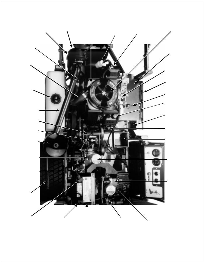
Component Identification
|
Donaldson Air Cleaner |
|
Air Cleaner |
|
Air Cleaner |
||
|
(Primary Air Cleaner) |
|
Cover |
|
Base Plate |
||
|
|
|
|
|
|
|
|
Air Restriction Indicator |
|
|
|
|
|
|
|
|
(Not Visible) |
|
|
|
|
|
|
|
|
|
|
|
|
|
|
|
|
|
|
|
|
|
|
|
Air Intake Hose |
|
|
|
|
|
|
(Primary to Secondary) |
|
|
|
|
|
|
|
|
|
|
|
|
|
|
|
|
|
|
|
|
|
|
|
Fuel Tank
Precleaner
Tube
Jackshaft
PTO Gearbox
Dipstick
Turbine
Precleaner
RH Transmission
Lockout Lever
30 Amp
Circuit Breaker
PTO
Clutch Lever
|
|
|
|
|
|
Positive (+) |
|
Negative (-) |
|
|
|
Battery Cable |
|
Battery Cable |
|
Battery |
|
|
|
|
|
Engine Air Cleaner |
Fuel Filter |
|
Fuel Pump |
|
(Secondary) |
Muffler Grass
Shield
Throttle and
Choke Linkage
Muffler Heat
Shield
Oil Dipstick/Oil Fill
Rubber Bumper
(Catcher Support)
Muffler
20 Amp Fuse
(Starter Solenoid)
GHS Blower
RH Hydrostatic
Transmission
LH Hydrostatic
Transmission
Neutral Safety |
|
LH Transmission |
Switch |
|
Lockout Lever |
|
|
|
Top View (Engine Compartment)
9
Safety Instructions
Pay particular attention to any information labeled
DANGER, WARNING, CAUTION, IMPORTANT, and NOTE in this manual.
When you see the Safety Alert Symbol (  ), read, understand, and follow the instructions. Failure to comply with safety instructions may result in personal injury.
The seriousness or degree of importance of each type of information is defined as follows:
DANGER
An IMMEDIATE hazard that WILL result in severe personal injury or DEATH, if warning is ignored and proper safety precautions are not taken.
WARNING
A POTENTIAL hazard that COULD result in severe personal injury or DEATH, if warning is ignored and proper safety precautions are not taken.
CAUTION
Possible hazards or unsafe practices that MAY result in MODERATE personal injury or property damage, or machine damage, if warning is ignored and proper safety precautions are not taken.
IMPORTANT: Identifies mechanical information demanding special attention, since it deals with the possibility of damaging a part or parts of the machine.
NOTE: Identifies information worthy of special attention.
Walker Manufacturing cannot predict every potentially dangerous situation. Therefore, items labeled as such in this manual do not cover all conceivable situations. Any person using procedures, tools, or control techniques not recommended by Walker Manufacturing must take full responsibility for safety.
The Walker Rider Lawnmower has been designed with many safety features to protect the operator from personal harm or injury. However, it is necessary for the operator to use safe operating procedures at all times. Failure to follow safety instructions contained in this manual may result in personal injury or damage to equipment or property.
If you have any questions concerning setup, operation, maintenance, or safety, please contact your authorized Walker Mower Dealer or call Walker Manufacturing Company at (970) 221-5614.
BEFORE OPERATING
1.Read and understand the contents of this Owner’s Manual before starting and operating the machine. Become thoroughly familiar with all machine controls and how to stop the machine and disengage the controls quickly. Replacement Owner’s Manuals are available by sending the Model and Serial Number to:
Walker Manufacturing Company
5925 East Harmony Road
Fort Collins, CO 80528
2.Never allow children to operate rider mower.
Do not allow adults to operate without proper instruction.
3.Clear the area to be mowed of any foreign objects which may be picked up and thrown by cutter blades. Pick up all sticks, stones, wire, and any other debris.
4.Keep everyone, especially children and pets, a safe distance away from the area being mowed.
Do not mow with bystanders in the area.
5.Do not operate the machine barefoot or wearing sandals, sneakers, tennis shoes, or similar lightweight footwear. Wear substantial protective footwear.
10

Safety Instructions
6.Do not wear loose fitting clothing that could get caught in moving parts. Do not operate this machine while wearing shorts; always wear adequate protective clothing, including long pants. Wearing safety glasses, safety shoes, and a helmet is advisable and required by some local ordinances and insurance regulations.
7.Prolonged exposure to loud noise can cause impairment or loss of hearing. Operator hearing protection is recommended; particularly for continuous operation of the GHS Model due to blower noise level. Wear a suitable hearing protective device, such as earmuffs or earplugs.
8.Keep all protective shields and safety devices in place. If a protective shield, safety device, or decal is damaged, unusable, or missing, repair or replace it before operating the machine.
9.Be sure interlock switches are functioning correctly, so the engine cannot be started unless the Forward Speed Control lever is in the NEUTRAL-PARK position, and the PTO clutch is in the DISENGAGED position. Also, the engine should stop if the operator lifts off the seat with the PTO clutch in the ENGAGED position.
10.Handle gasoline with care. Gasoline is highly flammable and its vapors are explosive:
a.Use an approved fuel container.
b.Never add fuel to a running engine or hot engine (allow hot engine to cool several minutes).
c.Keep matches, cigarettes, cigars, pipes, open flames, or sparks away from the fuel tank and fuel container.
d.Always fill the fuel tank outdoors using care. Fill to about one inch from the top of the tank. Use a funnel or spout to prevent spilling.
e.Replace the machine fuel cap and container cap securely and clean up any spilled fuel before starting the engine.
11.Never attempt to make any adjustments while the engine is running, except where specifically instructed to do so.
12.The electrical system battery contains sulfuric acid. Avoid any contact with skin, eyes, and clothing. Keep the battery and acid out of reach of children.
OPERATING
1.Operate the mower only in daylight or in good artificial light with good visibility of the area being mowed.
2.Sit on the seat when starting the engine and operating the machine. Keep feet on the deck footrests at all times when the tractor is moving and/or mower blades are operating.
3.For a beginning operator, learn to steer (maneuver) the tractor with a slow engine speed before attempting any mowing operation. Be aware that, with the front mounted mower configuration, the back of the tractor swings to the outside during turns.
4.Remember, for an emergency stop, the forward motion of the tractor can always be stopped by pulling the Forward Speed Control (FSC) into the NEUTRAL-PARK position.
5.Disengage the blade clutch and put the FSC in the NEUTRAL-PARK position before starting the engine (an ignition interlock switch normally prevents starting of the machine if these controls are in the OPERATING position).
6.Do not run the engine in a confined area without adequate ventilation. Exhaust fumes are hazardous and can be deadly.
7.Do not carry passengers - maximum seating capacity is one (1) person.
8.Watch for holes, rocks, and roots in the terrain and for other hidden hazards. When mowing tall grass, mow higher than desired to expose any hidden obstacles. Then, clean the area and mow to the desired height.
9.Avoid sudden starts or stops. Before backing the machine up, look to the rear to be sure no one is behind the machine. Watch carefully for traffic when crossing or working near roadways.
11

Safety Instructions
10.Disengage the blade drive when transporting the machine across drives, sidewalks, etc. Never raise the mower deck while blades are rotating.
11.The maximum recommended side slope operating angle is 20 degrees or 33% grade.
When operating the machine on a slope, reduce speed and use caution to start, stop, and maneuver. To prevent tipping or loss of control of the machine, avoid sharp turns or sudden changes in direction.
12.Never adjust cutting height with the engine running. Before adjusting cutting height or servicing, disengage the blade clutch (PTO), stop the engine, and remove the ignition key. Wait for all movement to stop before getting off the seat.
NOTE: A blade/blower brake should normally stop drive line rotation within five (5) seconds of disengaging the PTO clutch.
13.For side discharge mower decks, do not operate with the grass deflector chute removed.
Keep the deflector in the lowest possible position.
14.For tractors equipped with tilt-up deck, observe the following recommendations:
a.Do not move tractor with deck in tilt-up position.
b.Never tilt body forward with deck in tilt-up position.
15.For GHS equipped models, do not operate the machine with the grass catcher in the DUMP position or with the back door OPEN. Dangerous projectiles may be thrown out of the discharge chute or the back of the grass catcher.
16.For GHS equipped models, use care when closing the grass catcher door. Keep fingers and hands away from the hinge and pinch points when the door is being closed. Also, keep fingers and hands clear of the door frame. The door is held closed with springs and the door may slam shut with considerable force.
17.In case of a clogged or plugged mower deck or GHS catching system:
a.Disengage the blade clutch (PTO) and turn the engine off before leaving the seat.
b.LOOK to make sure blade drive shaft and blower drive pulley movement has stopped before trying to unclog the system.
c.Disconnect the spark plug wires.
d.Never place hands under the deck or in the GHS blower - use a stick or similar tool to remove clogged material.
18.If the cutting blades strike a solid object or the machine begins to vibrate abnormally, immediately disengage the blade clutch (PTO), stop the engine, and wait for all moving parts to stop. To prevent accidental starting, disconnect the spark plug wires. Thoroughly inspect the mower and repair any damage before restarting the engine and operating the mower.
Make sure cutter blades are in good condition and blade nuts are torqued to 60 ft-lb (81.3 N×m).
19.Do not touch the engine or muffler while the engine is running or immediately after stopping the engine. These areas may be hot enough to cause serious burns.
20.When leaving the machine unattended, disengage the blade clutch (PTO), stop the engine, and remove the key.
MAINTENANCE
1.To prevent accidental starting of the engine when servicing or adjusting the machine, remove the key from the ignition switch and disconnect the spark plug wires.
2.To reduce fire hazards, keep the engine free of grass, leaves, excessive grease, and dirt.
3.Keep all nuts, bolts, and screws tight to ensure the machine is in a safe, working condition. Check the blade mounting nuts frequently, making sure they are tight.
12

Safety Instructions
4.Perform only maintenance instructions described in this manual. Unauthorized maintenance operations or machine modifications may result in unsafe operating conditions.
5.If the engine must be running to perform a maintenance adjustment, keep hands, feet, and clothing away from moving parts. Do not wear jewelry or loose clothing.
6.Always use the proper engine service manual when working on the engine. Unauthorized maintenance operations or modifications to the engine may result in unsafe operating conditions.
7.Altering the equipment or engine in any manner which adversely affects its operation, performance, durability, or use will VOID the warranty and may cause hazardous conditions.
8.Never attempt to disconnect any safety devices or defeat the purpose of these safety devices.
9.Do not change the engine governor settings or overspeed the engine. The governor has been factory-set for maximum-safe engine operating speed.
10.Use genuine factory replacement parts.
Substitute parts may result in product malfunction and possible injury to the operator and/or others.
11.Use care when charging the battery or performing maintenance on the battery and electrical system:
a.Make sure the battery charger is unplugged before connecting or disconnecting cables to the battery.
b.Charge the battery in a well-ventilated space, so gases produced while charging can dissipate. Make sure the battery vents in the caps are open.
c.Keep sparks, flames, and smoking materials away from the battery at all times. To avoid sparks, use care when removing battery cables from posts.
d.Disconnect both battery cables before unplugging any wiring connectors or making repairs on the electrical system.
IMPORTANT: Keep all applicable manuals immediately accessible to anyone who may operate or service this machine.
13

Safety Instructions
SAFETY, CONTROL, AND INSTRUCTION DECALS
Safety, Control, and Instruction Decals are installed on the machine;
if any are missing, illegible, or damaged, a replacement should be ordered and installed before putting the machine into operation. The Decal Part Number is listed below and in the Parts Manual.
Adjacent to Blower Discharge Chute
through Body (5804)
Each End of Mower Deck (5808)
|
|
Hydrostat Oil |
SD Deck Discharge Shield (5848) |
Front Body Adjacent to |
Reservoir (5810) |
RH Steering Lever (7818) |
|
Engine Shroud (5855)
On Body Adjacent to Clutch
Control Lever (5806)
Rear of Grass Catcher Exhaust Screen (5869)
Right Side of Front Body, Below |
Rear Cross Member of Front Body (8825) |
Front Body Latch Release (7820) |
|
14

Safety Instructions
SAFETY, CONTROL, AND INSTRUCTION DECALS
Safety, Control, and Instruction Decals are installed on the machine;
if any are missing, illegible, or damaged, a replacement should be ordered and installed before putting the machine into operation. The Decal Part Number is listed below and in the Parts Manual.
Jackshaft Support Adjacent
to Dipstick (7827)
Deck Gearbox Cover (5807-1)
Deck Carrier Frame (8647)
Gear Axle (5810-1) Deck Carrier Frame (8653)
On Engine (6810)
Deck Carrier Frame (5865)
Catcher Safety Latch,
RH Side (5874)
Right Side, Below Operator Seat (7809)
Top of Blower Housing (5819)
Left Side of Operator Seat (8819)
Catcher Door Hinge Bar,
LH and RH Sides (5868)
Left Side of Operator Seat (7819)
Instrument Panel (8823) |
Fender, RH Side (7802) |
15
Assembly Instructions
SETUP INSTRUCTIONS
Walker Mowers are shipped partially assembled. After uncrating the tractor and mower deck, initial setup is required.
NOTE: During the process of unpacking, any damaged or missing parts should be noted and reported to the delivering carrier immediately (put in writing within 15 days). The carrier will provide directions for proceeding with a claim to receive compensation for damage.
Tire Installation (Tractor)
∙Install the drive tires using the eight (8) lug bolts that are supplied with the owner’s packet of materials. Drive tires are 18 x 9.50-8, 4-ply; rear tires are 13 x 5.00-6, 4-ply.
∙Check and adjust the inflation of the tires. The tire inflation recommendations are:
Drive = 15 PSI (103 kPa)
Rear = 20 PSI (137 kPa)
Battery Service
Raise front mower body up for battery access (refer to Front Body Latch Release in Operating Instructions). Check the battery for electrolyte level and charge. The electrolyte level should be at the bottom of the vent wells [1/4 to 1/2 in. (6 to 13 mm) above plates]. If the specific gravity is less than 1.225, the battery needs charging. If the battery has been shipped dry, or is wet but needs service, refer to the following instructions.
Wet Battery Service
If the battery has been shipped wet, but the electrolyte level is low or the battery needs to be charged then:
1.Fill each battery cell with drinking water to the bottom of the vent wells.
2.Charge battery. Refer to Battery Charging in this section.
Dry Battery Service
DANGER
Activating a battery can be dangerous. The battery should be taken to a reliable service station, battery store, or power equipment dealer where a trained technician can activate the battery safely. DO NOT attempt to activate the battery unless you are experienced in battery service work. The following activation and charging instructions are provided for use by a trained battery technician.
DANGER
Battery electrolyte is a poisonous and corrosive sulfuric acid solution.
∙Avoid spillage and contact with skin, eyes, and clothing - causes severe burns.
∙To prevent accidents, wear safety goggles and rubber gloves when working with electrolyte.
∙Neutralize acid spills with baking soda and water solution.
To fill (activate) battery with electrolyte (if battery has been shipped dry):
1.Remove the battery hold down bar, disconnect the battery cables and lift the battery out of the tray.
IMPORTANT: Battery must be removed from the mower before filling with electrolyte.
IMPORTANT: Obtain and use only battery grade sulfuric acid electrolyte with a 1.265 specific gravity to activate the battery. DO NOT use water or any other liquid during initial activation.
2.Remove the filler caps and carefully fill each cell until the electrolyte is just above the plates.
16
Assembly Instructions
3.After the battery is filled with electrolyte, replace the filler caps and charge the battery. Refer to
Battery Charging.
Battery Charging
DANGER
BATTERIES PRODUCE EXPLOSIVE GASES
∙Charge the battery in a well-ventilated area, so that gases produced while charging can dissipate.
∙Keep sparks, flames, and smoking materials away from the battery at all times.
∙Make sure the battery cap vents are open after the battery is filled with acid (check manifold vent on each cap).
∙Make sure the battery charger is unplugged before connecting or disconnecting cables to the battery.
1.Charge the battery at 15 amps for 10 minutes. DO NOT exceed 20 amps maximum recommended charging rate. Charge until specific gravity is at least 1.250. Total charging time should not exceed one (1) hour.
2.After charging the battery, adjust the electrolyte level to the bottom of the vent wells [1/4 to 1/2 in. (6 to 13 mm) above the plates].
IMPORTANT: DO NOT overfill the battery. Electrolyte will overflow through the vented caps onto parts of the machine and WILL result in severe corrosion.
3.Install battery.
Battery Installation
Install the battery in the mower as shown in Battery Installation photo. Connect the positive and negative cables to the proper battery terminal (red cable and boot connects to the Positive (+) terminal). Slide the rubber boot up and over the battery post, making sure it covers the post completely to prevent an electrical short.
WARNING
Make sure the battery cap vents are open. Improper venting of the battery COULD cause a battery explosion.
Battery Clamp
Secured by
Wing Nut(s)
(+) Battery Cable
Connection
Battery Installation
Mower Deck Assembly
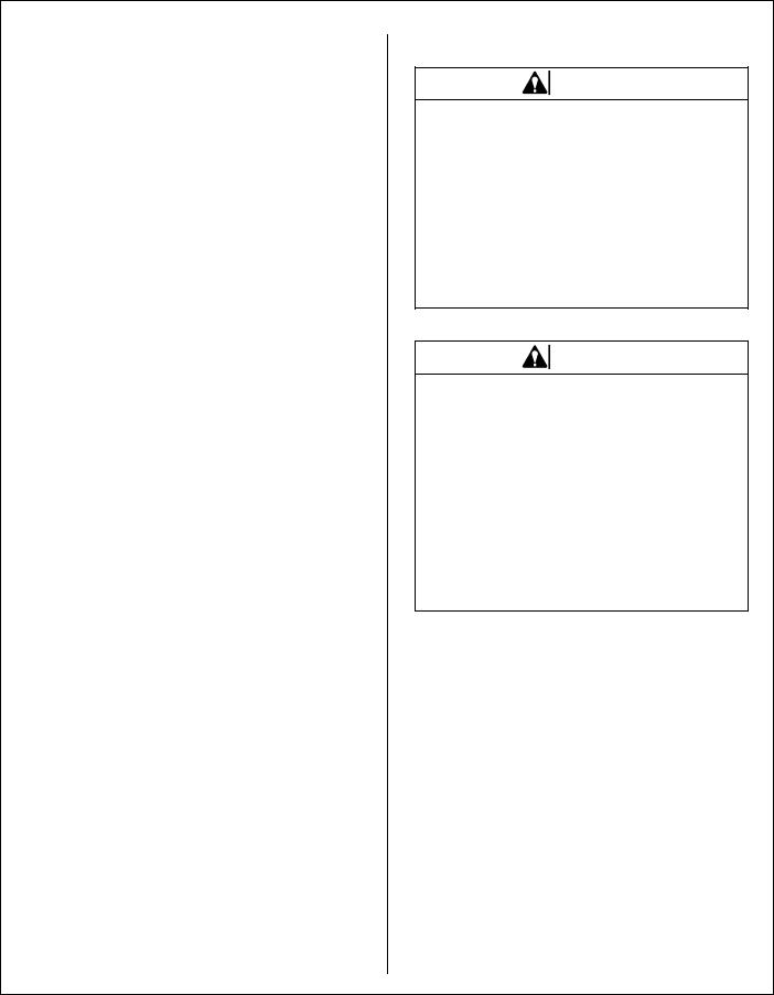
Deck Caster Wheels Installation
1.Remove the bolt, nut, axle spacer tube, and spacer washers from each deck caster wheel fork.
NOTE: Spacer washers are used only when the optional semi-pneumatic deck wheels (8.25 x 2.75) are installed.
2.Fit the axle spacer tube through the wheel hub, position the spacer washer on each side of the hub (if used), and fit the assembly into the wheel fork.
3.Insert the 3/8-16 x 4-1/2 in. bolt through the wheel fork with the bolt head to the outside and install the 3/8-16 in. Keps nut.
4.Tighten the bolt and nut until the axle spacer tube bottoms against the inside of the wheel fork (will not turn) while the wheel and spacer washers (if used) spin freely without binding.
17
Assembly Instructions
Grease Fitting
Locations
Spacer Washer
Axle Spacer Tube
Deck Caster Wheel Installation
NOTE: If semi-pneumatic wheels are installed, make sure the spacer washers fit over the spacer tube and are not caught between the fork and the end of the tube. The washers should move freely on the axle spacer tube.
5.Grease the caster wheel bearings and caster pivot bearings - one grease fitting for each wheel and each pivot.
Deck Discharge Chute Installation
(GHS Rear Discharge Models Only)
Mount the discharge chute hinge on top of the deck discharge opening using the 1/4-20 x 1/2 in. socket button head bolt and 1/4-20 ESNA nut. Position the bolt with the head inside of the chute and the nut on the outside.
Carrier Frame
Tube Sockets
Attach Chute
Attach Guard
Nut on Top
Discharge Chute and PTO Shaft Guard Installation on Rear Discharge Deck
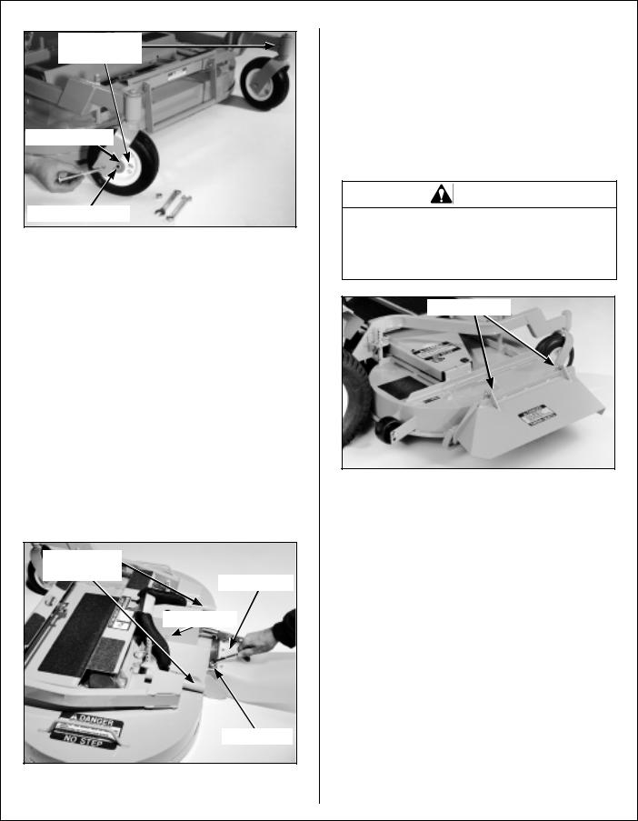
Deck Discharge Shield Installation
(Side Discharge Models Only)
Attach the deck side discharge shield by positioning the shield hinge lug in front of the deck mount and fastening with two 3/8-16 x 1-1/4 in. bolts, 3/8-16 ESNA nuts, and 3/8 in. wave spring washers. The wave washers fit between the two hinging surfaces. Tighten the nuts until the shield moves freely but is not loose.
WARNING
DO NOT operate the machine without the grass deflector chute attached and in the lowest possible position.
Attach Shield
Discharge Shield Installation
on Side Discharge Deck
PTO Shaft Guard Installation
Position the shaft guard as shown and mount with two 1/4-20 x 1/2 in. bolts.
Mower Deck lnstallation on Tractor
Deck Installation
1.Lightly grease each deck support arm (2) on the tractor. Refer to Mower Deck Installation photo on next page for location of deck support arm.
2.Engage the deck carrier frame tube sockets on the tractor support arms (refer to Discharge
Chute and PTO Shaft Guard Installation photo for socket location). Slide the deck onto the support arms: all the way if SD equipped model, approximately 3 in. (76 mm) if GHS equipped model.
18
Assembly Instructions
NOTE: When installing the DSD52 or DSD62 Mower deck, make sure to retract the dolly wheel after mounting the deck on the tractor.
3.If the deck is rear discharge (GHS equipped model), the rear discharge chute will need to be aligned and connected to the blower inlet during the last 2 in. (51 mm) of slide action on the support arms.
NOTE: Raising the mower body may be helpful in fitting and guiding the deck chute into the blower.
4.Install the hitch pin through the hole on the end of each support arm to lock the deck in place (refer to Deck Counterweight Spring Installation photo). Two (2) hitch pins are included in the owner’s packet of materials.
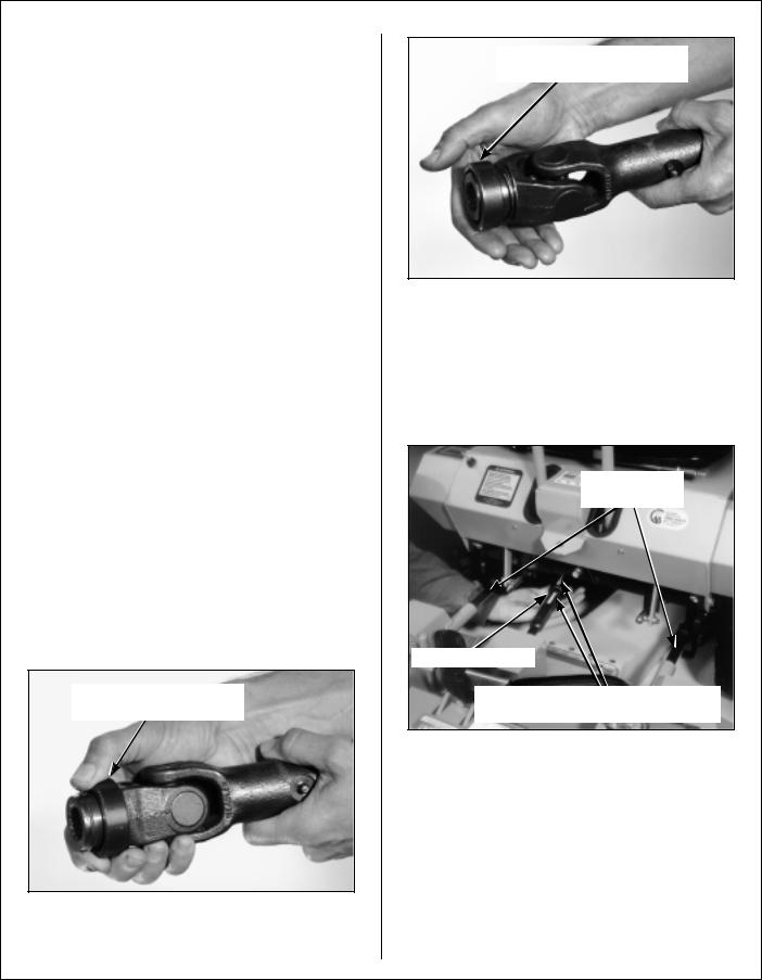
5.Connect the mower deck PTO drive shaft assembly to the tractor with the splined quick disconnect coupler. This coupler simplifies shaft alignment and installation.
a.Use the arrows on the shaft and tube to align and slide the PTO quick coupler onto the deck rectangular shaft.
b.Reaching under the tractor, pull the ring back on the coupler, slide onto the spline shaft on the tractor, and release the ring.
IMPORTANT: To prevent damage to the mower, make sure the PTO shaft assembly is securely locked on the tractor, with the locking balls fully seated in the groove and the ring in the full forward position (refer to the Coupler Ring “Locked” Position photo). After installation, pull on the shaft to check for security.
Pull Back Spring-Loaded
Coupler Ring
Installing PTO Quick Coupler
Spring-Loaded Coupler Ring
In Fully Forward Position
Coupler Ring “Locked” Position
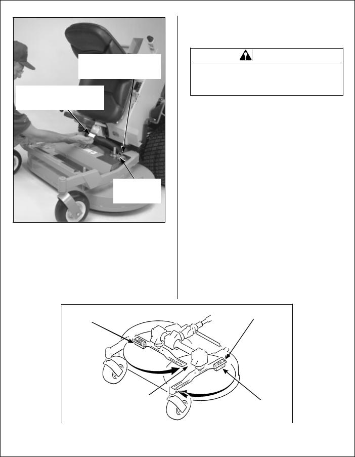
6.Raise the front mower body (instead of lifting the front of deck) and clip the counterweight springs to the receptacle on front of body. Lower the front body to tension the springs. (Refer to Deck Counterweight Spring Installation Photo.)
Grease Deck
Support Arms
PTO Connection
Arrows on Shaft and Tube (used to align when sliding together)
Mower Deck Installation
(PTO Shaft Connection)
7.With the counterweight springs connected, the weight on the deck caster wheels should be 15 to 25 Ib (6.8 to 11.3 kg). Check this weight by lifting on the front of the deck carrier frame. If required, the spring tension can be adjusted by tightening or loosening the elastic stop nuts located underneath the lower spring hook. Refer to Deck Counterweight Spring Installation photo.
19
Assembly Instructions
Spring Tension Adjustment
Nut Located Under Lower
Spring Hook (Not Visible)
Counterweight Springs Clip
Onto Body With Forward
Body Tilted Up
Hitch Pins
Lock Deck On
Support Arms
Deck Counterweight Spring Installation
Deck Leveling
1.Position mower on a smooth, level surface. Set the cutting height to the highest position - 4 in. (102 mm) - for easy access under the deck to measure blade height. Refer to ADJUSTING CUTTING HEIGHT in Operating Instructions.
NOTE: A block of wood cut 4 in. (102 mm) high is a convenient gauge to measure blade height above ground during the leveling process.
WARNING
The machine must be shut off during this procedure.
2.Check the side-to-side level. Rotate each blade sideways and measure the distance from blade tip to ground on each side. If measurements vary more than 1/8 in. (3 mm), add a washer shim under the deck support pins on the low side to level the deck.
3.Check the front-to-rear level. Rotate the blades to point forward. Measure the distance from blade tip to ground on the front and rear. The rear of the blade should be 1/8 to 1/4 in. (3 to 6 mm) higher than the front of the blade; shim the rear (or front) deck support pins equally to achieve at least 1/8 in. (3 mm) difference.
NOTE: The mower deck and support frame are jig welded; within normal tolerances, very little, if any, shimming should be required to level the deck. Tire pressure will influence the levelness of the deck. Check the tire pressure as a possible cause of the deck not being level.
|
|
Should be 1/8 in. (3 mm) |
4 in. (102 mm) |
|
|
|
to 1/4 in. (6 mm) higher |
|
Wood Block |
|
|
|
at the rear of the blade |
|
|
|
|
|
|
Should not vary more
than 1/8 in. (3 mm) |
4 in. (102 mm) |
|
Wood Block |
||
side-to-side |
||
|
||
|
|
|
Deck Leveling |
|
20
Assembly Instructions
PREOPERATING CHECKLIST
Before operating the mower for the first time, and as a routine before daily operations, it is important to make sure the mower is properly prepared and ready for operation. The following is a list of items to be checked. (For a mower with frequent operation, some of these items will not need to be checked every day, but the operator should be aware of the condition of each.)
For proper fuels and lubricants refer to Specifications.
FILL FUEL TANK
Fill the fuel tank using clean, fresh automotive grade unleaded gasoline (87 octane rating minimum).
DANGER
Handle gasoline with care. Gasoline is highly flammable and its vapors are explosive. Use safe refueling procedures:
∙DO NOT fill fuel tank with the engine running.
∙If the engine is hot, allow to cool before refueling.
∙Use an approved fuel container.
∙Fuel the mower outdoors.
∙DO NOT smoke while refueling.
∙Avoid spilling fuel; use a funnel or spout.
∙DO NOT overfill the fuel tank; fill up to about 1 in. (25 mm) below the top of tank.
IMPORTANT: DO NOT permit dirt or other foreign matter to enter the fuel tank. Wipe dirt from around the filler cap before removing. Use a clean fuel storage container and funnel.
IMPORTANT: DO NOT mix oil with gasoline. Always use fresh, automotive grade gasoline. DO NOT use premium, white, or high-test gasoline. DO NOT use additives, such as carburetor cleaners, deicers, or moisture removing agents. DO NOT use gasoline blended with methyl alcohol.
CHECK ENGINE CRANKCASE OIL LEVEL
Check the engine crankcase oil level before use and after each 5 hours of continuous operation. Refer to LUBRICATION for Checking Engine Crankcase Oil Level in Maintenance Instructions.
CHECK AND SERVICE ENGINE AIR CLEANER SYSTEM
∙Check air restriction gauge to make sure there is no red indication showing.
∙Check condition, cleanliness, and security of the complete air cleaner system (clean primary air filter every 100 hours). For detailed procedures, refer to CLEANING the Engine Air Cleaner System in Maintenance Instructions.
ADJUST CARBURETOR (Initial Start-up Only)
Refer to ADJUSTMENTS of Carburetor in Maintenance Instructions.
CHECK ENGINE COOLING SYSTEM
Check that the engine cooling air intake screen is free of obstruction by grass clippings or debris and clean if required. Also, cylinder head cooling fins should be inspected and cleaned if any build-up of debris is noted [remove two (2) cylinder head access panels to inspect and clean].
Check performance of the cooling system by starting the engine, holding a hand adjacent to the cylinder heads, and feeling the cooling airflow.
DANGER
Make sure to keep hands clear of exhaust pipe, muffler, and moving parts when checking airflow.
21
Assembly Instructions
CHECK GEAR AXLE OIL LEVEL
Refer to Gear Axle Lubrication in Maintenance Instructions.
INSPECT FOUR (4) DRIVE BELTS
Engine PTO Drive, Jackshaft Drive, Hydrostatic Ground Drive, and GHS Blower Drive (if equipped).
CHECK HYDROSTATIC TRANSMISSION OIL LEVEL
Refer to LUBRICATION for Checking Hydrostatic Transmission Fluid Level in Maintenance Instructions.
CHECK BATTERY ELECTROLYTE LEVEL
Refer to CHECKING/SERVICING the Battery in
Maintenance Instructions.
CHECK FUNCTIONS OF INSTRUMENT PANEL AND WARNING HORN
Turn the ignition key to the RUN position. Voltmeter, Oil Pressure Light, and Warning Horn should all operate, indicating normal function.
CHECK TIRE PRESSURE
Deck Caster Wheel = 20 PSI (137 kPa)
Drive |
= |
15 PSI (103 kPa) |
Rear |
= |
20 PSI (137 kPa) |
CHECK AND CLEAN GRASS BUILDUP UNDERNEATH MOWER DECK (and inside GHS blower, if equipped)
Refer to CLEANING the GHS Blower in Maintenance Instructions for blower cleaning information.
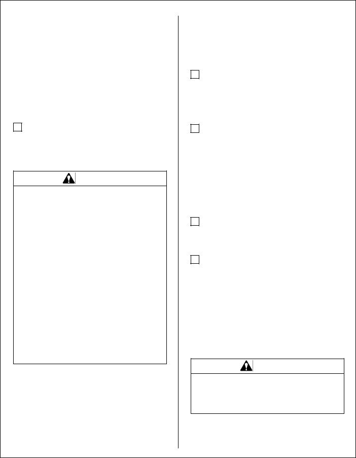
NOTE: Mower deck is secured in raised position for cleaning and changing blades by hooking the deck lift rod into the body bracket below the counterweight spring clip. The rod is hinged and is stowed along the footrest of the deck carrier frame. A hitch pin on the end of the rod is used to secure it in place with the deck raised.
Counterweight |
Spring Clip |
Deck Lift |
Rod |
Body |
Bracket |
Deck Secured in UP Position (Non-Tilting)
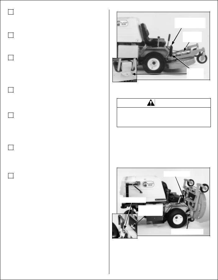
DANGER
Never operate cutter blades with deck in raised position because it is hazardous.
If equipped, the tilt-up deck can be secured in the raised position by unlocking the deck lock levers on each side of the carrier frame and inserting the deck hook into the tilt-up latch on the tractor body. Before operating the tractor, make sure to re-engage the deck lock levers after lowering the deck to the normal operating position.
Tilt-Up Latch |
Tilt-Up Latch |
Tilt-Up Hook |
on Deck |
Deck Lock Lever |
Deck Secured in TILT-UP Position
22

Assembly Instructions
CAUTION
Do not operate machine with deck tilt-up pivot joint unlocked.
DANGER
Do not operate the mower with deck in tiltup position. Do not move the tractor with the deck in the tilt-up position.
CHECK MOWER BLADE CONDITION, SHARPNESS, AND SECURITY OF MOUNTING
The blade mounting nut should be tightened to 60 ft-lb (81.3 N×m). If blade sharpening is required, refer to CHECKING/SERVICING for Sharpen Mower Blades in Maintenance Instructions.
ADJUST MOWER CUTTING HEIGHT, IF REQUIRED
Position the hitch pins in the four deck support pins. Refer to the “Cutting Height Adjustment” decal on the deck gearbox cover.
PERFORM ANY ADDITIONAL PROCEDURES called for on the MAINTENANCE SCHEDULE CHART in Maintenance Instructions.
23
Operating Instructions
CONTROL IDENTIFICATION, LOCATION, AND FUNCTION
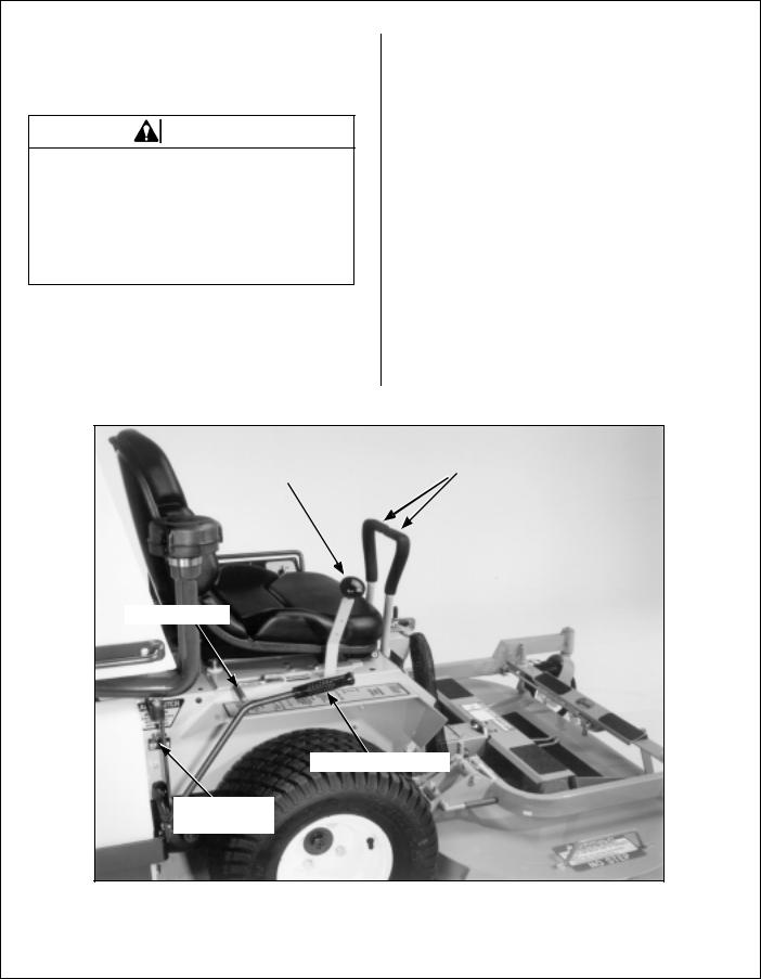
Operating Controls
CAUTION
Before operating the mower, become familiar with the location and function of all operator controls. Knowing the location, function, and operation of these controls is important for safe and efficient operation of the mower.
Engine Choke
The choke control lever (black knob) is located on the left side of the seat. To start a cold engine, move the choke control forward to the ON position. After engine starts, move the choke control toward the OFF position, keeping enough choke to allow the engine to run smoothly as it warms up. As soon as possible, move the choke to the OFF position. A warm engine requires little or no choke for starting.
IMPORTANT: Make sure the choke is in the OFF position during normal engine operation; running with the choke in the ON position CAN damage the engine.
Forward Speed Control |
|
Steering Levers |
(FSC) |
|
|
|
|
|
|
|
|
Parking Brake
Blade Clutch (PTO)
Front Body
Latch Release
Operating Controls
24
Loading...