


OWNER’S MANUAL
Safety, Assembly, Operating, and Maintenance Instructions
and ILLUSTRATED PARTS MANUAL
Model MB (18 HP)
™
Please Read and Save These Instructions |
Effective Date: 10-01-04 |
For Safety, Read All Safety and Operation |
P/N 4000-1 |
Instructions Prior to Operating Machine |
Price $5.00 |

Foreword
Thank you. . .for purchasing a Walker mower. Every effort has been made to provide you with the most reliable mower on the market, and we are sure you will be among our many satisfied customers. If for any reason this product does not perform to your expectations, please contact us at (970) 221-5614. Every customer is important to us. Your satisfaction is our goal.
Please. . .read this manual thoroughly! This manual is to be used in conjunction with the engine manufacturer’s manual for the specific engine on the mower model you have purchased. Before you operate your new mower, please read this entire manual. Some of the information is crucial for proper operation and maintenance of this mower - it will help protect your investment and ensure that the mower performs to your satisfaction. Some of the information is important to your safety, and must be read and understood to help prevent possible injury to the operator or others. If anything in this manual is confusing or hard to understand, please call our service department, at (970) 221-5614, for clarification before operating or servicing this mower.
This manual covers Model MB with the Briggs & Stratton Vanguard 18 HP gasoline engine.
All shields and guards must be in place for the proper and safe operation of this machine.
Where they are shown removed in this manual, it is for illustration purposes only. Do not operate this machine unless all shields and guards are in place.
Specifications given are based on the latest information available at the time this manual was produced.
Walker Mfg. Co. is continually striving to improve the design and performance of its products. We reserve the right to make changes in specifications and design without thereby incurring any obligation relative to previously manufactured products.
Sincerely,
WALKER MANUFACTURING COMPANY
Bob Walker, President

Table of Contents
Owner’s Manual
General Information ________________ 3
HIGHLIGHTED INFORMATION _____________ 3
GLOSSARY ____________________________ 3
IDENTIFYING NUMBER LOCATIONS________ 3 ENGINE SERIAL NUMBER LOCATION ______ 4
SERVICING OF ENGINE AND
DRIVETRAIN COMPONENTS ______________ 4
Specifications _______________________ 5
Component Identification___________ 8
Safety Instructions _________________ 11
BEFORE OPERATING ___________________ 11 OPERATING ___________________________ 12 MAINTENANCE ________________________ 13
SAFETY, CONTROL, AND
INSTRUCTION DECALS _________________ 15
Assembly Instructions _____________ 17
SETUP INSTRUCTIONS _________________ 17 Battery Service _______________________ 17 Mower Deck Assembly ________________ 17
Deck Caster Wheels Installation ________ 17 Deck Discharge Shield Installation ______ 17 PTO Shaft Guard Installation __________ 18 Tilt-Up Roller Wheel Installation ________ 18
Mower Deck Installation on Tractor ______ 18
Deck Installation ____________________ 18 Deck Leveling ______________________ 20
PREOPERATING CHECKLIST ____________ 21
Operating Instructions _____________ 24
CONTROL IDENTIFICATION,
LOCATION, AND FUNCTION _____________ 24
Ignition Switch _______________________ 24 Engine Choke ________________________ 25 Engine Throttle_______________________ 25
Forward Speed Control (FSC)___________ 25
Steering Levers ______________________ 25 PTO Switch __________________________ 25 Parking Brake ________________________ 26
Transaxle Lockout Rods _______________ 26
Hourmeter ___________________________ 26 STARTING THE ENGINE _________________ 28
ADJUSTING GROUND
SPEED AND STEERING _________________ 28
ENGAGING THE MOWER ________________ 30
STOPPING THE MACHINE _______________ 31 ADJUSTING CUTTING HEIGHT ___________ 31
TRANSAXLE LOCKOUTS________________ 32
RECOMMENDATIONS FOR MOWING ______ 32
RECOMMENDATIONS FOR TILT-UP DECK OPERATION/TRANSPORT _______________ 33
Maintenance Instructions__________ 34
MAINTENANCE SCHEDULE CHART _______ 34
IMPORTANT TIPS FOR CARE OF THE
BRIGGS & STRATTON ENGINE___________ 35
Fuel System _________________________ 35 Starting _____________________________ 35 Cooling System ______________________ 35 Air Cleaner __________________________ 35 Oil _________________________________ 35
LUBRICATION _________________________ 36 Engine Oil ___________________________ 36 Engine Break-In Oil __________________ 36
Checking Engine Crankcase Oil Level ___ 36 Changing Engine Crankcase Oil/Oil Filter 36
Grease Fitting and Oil Point Lubrication__ 37 Mower Deck Gearbox Lubrication _______ 40 Transaxle Lubrication _________________ 40
CLEANING ____________________________ 41
Engine Air Cooling System ____________ 41
Air Cleaner System __________________ 41
Grass Buildup in Mower Housing _______ 42 Transaxle Cooling Fins ________________ 43
CHECKING/SERVICING _________________ 43
Security of Air Cleaner System _________ 43
Battery _____________________________ 43
Cleaning the Terminals _______________ 43
Charging the Battery _________________ 43 Tire Pressure ________________________ 44
Sharpen Mower Blades ________________ 44
Drive Belts __________________________ 45
Mower Deck Gearbox Oil Seals _________ 45
Spark Plugs _________________________ 45 Breaker Points _______________________ 45
Fuel Lines and Clamps ________________ 45
Blade Brake Action ___________________ 46
REPLACING/REPAIRING ________________ 46
Drive Belts __________________________ 46 Engine/PTO Belt ____________________ 47 Ground Drive Belt ___________________ 48 Fuel Filter ___________________________ 49
Blade Overload Shear Bolts ____________ 49
PTO Shear Pin _______________________ 49 Mower Blades _______________________ 50
1

Table of Contents
ADJUSTMENTS ________________________ 51 Steering Levers ______________________ 51
Tilt-Up Deck Adjustable Stop ___________ 51
ELECTRICAL SYSTEM __________________ 51
Illustrated Parts Manual
TRACTOR DECALS _____________________ 52
BODY / CHASSIS ASSEMBLY ____________ 54
MAIN COMPONENT
POWER TRANSMISSION ________________ 56 ENGINE GROUP _______________________ 58
HYDROSTATIC GROUND
DRIVE ASSEMBLIES ____________________ 60
STEERING CONTROL ASSEMBLIES_______ 62 ELECTRICAL ASSEMBLY________________ 64
WIRING SCHEMATIC____________________ 66
Operator’s Notes ___________________ 67
Maintenance And Service
Record Sheet _______________________ 68
Warranty ___________________________ 69
2

General Information
HIGHLIGHTED INFORMATION
Walker Manufacturing recommends that any service requiring special training or tools be performed by an authorized Walker Mower Dealer. There are several general practices to be aware of in the area of safety. Most accidents associated with the operation or maintenance of a Walker Mower are caused by disregarding basic safety precautions or specific warnings. Such accidents, in most cases, can be prevented by being aware of the dangers present.
Information of special importance has been highlighted in bold type in this manual. Refer to Safety Instructions for the meanings of DANGER, WARNING, CAUTION, IMPORTANT, and NOTE.
GLOSSARY
There are many terms that are either unique to this equipment or that are used as acronyms. The following terms and their definitions will help while using this manual:
•DECK is the mowing attachment mounted on the front of the tractor which includes the carrier frame, deck housing, blade drive gearboxes, and cutter blades.
•FORWARD SPEED CONTROL (FSC) controls the maximum forward speed of the tractor; functioning as a cruise control.
•GROUND DRIVE refers to the dual transaxles which drive the main wheels.
•TRANSAXLE transmits and controls power from the ground drive belt to the main drive wheel.
•LEFT HAND (LH) refers to the left-hand side of the tractor when the operator is seated facing forward in the tractor seat.
•POWER TAKE-OFF (PTO) transmits engine power to run the cutter blades.
•RIGHT HAND (RH) refers to the right-hand side of the tractor when the operator is seated facing forward in the tractor seat.
•SIDE DISCHARGE (SD) mows but does not collect the mowed material.
•STEERING LEVERS steer the tractor by controlling the two transaxles.
•TRACTOR is the prime mover, including the engine, drive train, operator seat, and controls to operate the mower.
•TRANSAXLE LOCKOUT RODS release the transaxles to permit freewheeling the tractor.
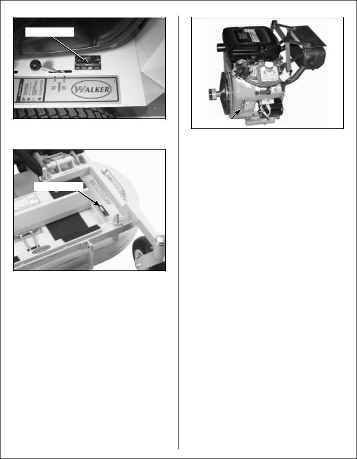
IDENTIFYING NUMBER LOCATIONS
The tractor serial number plate is affixed to the tractor body just below the left rear corner of the seat. The mower deck serial number plate is affixed alongside the angle iron framing on the LH side of the LH mower blade drive. Model and serial numbers are helpful when obtaining replacement parts and maintenance assistance. For ready reference, please record these numbers in the space provided.
Tractor Model No. _______________________
Tractor Serial No. _______________________
Deck Serial No. _______________________
Engine Model No. _______________________
Engine Serial No. _______________________
Date of Purchase _______________________
Fill In By Purchaser
3
General Information
Serial Number
Tractor Serial Number Location
Serial Number
Mower Deck Serial Number Location
ENGINE SERIAL NUMBER LOCATION
The Briggs & Stratton engine model, type, and code numbers are located on the left hand of the engine shroud. For the mower model covered by this manual, contact a Briggs & Stratton servicing dealer.
Serial Number
Engine Serial Number Location
SERVICING OF ENGINE AND DRIVETRAIN COMPONENTS
The detailed servicing and repair of the engine, transaxle and gearboxes are not covered in this manual. Only routine maintenance and general service instructions are provided. For the service of these components during the limited warranty period, it is important to find a local, authorized servicing agent of the component manufacturer. Any unauthorized work done on these components during the warranty period may void the warranty. If you have any difficulty finding an authorized outlet or obtaining warranty service, please contact our Service Department for assistance:
Walker Manufacturing Company
5925 E. Harmony Road
Fort Collins, CO 80528
1-970-221-5614
Service manuals are available for each of these components from their respective manufacturers as follows:
Briggs & Stratton |
Briggs & Stratton |
Engine |
800-233-3723 |
|
(24-hour hotline in |
|
USA & Canada) |
|
www.briggsandstratton.com |
Transaxle |
Hydro-Gear |
|
Sullivan, IL |
Gearboxes (Deck) Tecumseh Products Co.
900 North Street
Grafton, Wl 53024
4

Specifications
MODEL |
MB |
ENGINE |
|
Manufacturer/Model |
Briggs and Stratton Vanguard, 2 Cyl. OHV (Air-Cooled) |
Displacement |
34.7 cu. in. (570 cc) |
HP (@ 3600 RPM) |
18.0 |
Max. RPM (No Load) |
3600 ± 100 |
Governed RPM |
3600 ± 100 |
Max. Torque [ft-lb (N m) @ RPM] |
29.5 (40.5) @ 2400 |
Idle RPM |
1750 |
Spark Plug Type |
Champion RC14YC |
Spark Plug Gap |
.030 in. (.75 mm) |
Crankcase Capacity |
1.5 qts (1.4 liters) |
Crankcase Lubricant |
SF/SG/SH/SJ or Higher Grade Oil Only with 30W Viscosity |
|
Above 40° F (4° C) |
Fuel Tank Capacity |
3 Gallons (11.35 liters) |
Fuel |
Automotive Grade Unleaded Gasoline (85 Octane) |
Cooling System |
Air Cooled |
|
|
ELECTRICAL SYSTEM |
|
Battery |
12 Volt, 220 CCA (Interstate PC12/80) |
Charging System |
Flywheel Alternator |
Charging Output |
16 Amp DC (Regulated) |
System Polarity |
Negative Ground |
Ignition |
Magnetron® Electronic |
Starter |
12 Volt Electric Key and Solenoid Operated |
Interlock Switch |
Ignition Lockout by Seat Switch, Transmission Neutral and Blade Clutch |
|
|
TRANSMISSION |
|
Manufacturer/Model |
Dual, Independent Hydro-Gear Integrated Transaxles |
Steering |
Hand Lever Control / Individual Wheel |
Forward Speed Control |
Precision Friction Lock Lever, Cruise Control, with Neutral-Park |
|
Position |
Service Brake |
Dynamic Braking through Hydrostatic Transmission |
Parking Brake |
Mechanical Cog Lock in Transmission Gear |
Neutral |
Transmission Release by Manual Dump Valve |
Final Drive |
Direct Drive Axle from Transaxle |
5

Specifications
MODEL |
MB |
|
TRANSMISSION (continued) |
|
|
Transmission Fluid |
|
|
Factory Service |
20W50 Multi-Viscosity Motor Oil (Minimum SL Grade Oil) |
|
Transmission Fluid Capacity |
79 fl oz (2336 ml) |
|
Transmission Cooling |
Cooling Fan Mounted on Drive Pulley |
|
Ground Travel Speed |
|
|
Forward m.p.h. (km/h) |
0-8 (0-13) |
Infinitely Variable |
Reverse m.p.h. (km/h) |
0-8 (0-13) |
Infinitely Variable |
|
|
|
BLADE DRIVE |
|
|
PTO Shaft |
Sliding Spline Shaft with Two (2) High-Speed U-Joints |
|
Blade Spindle |
Each Blade (2) Mounts Direct on Peerless Right Angle |
|
|
Gearbox with Tee Gearbox in Center Connected to PTO Shaft |
|
|
(Complete Geared Drive, Peerless Model 1000 Gearboxes) |
|
Blade Drive Clutch and Brake |
12V Electrical (Electromagnetic Clutch and Brake) Switch |
|
|
Operated [Stops Blades within Five (5) Seconds of |
|
|
Disengagement] |
|
Max. Blade Speed |
2900 RPM |
|
[22 in. (56 cm) Blade] @ 3600 |
[16700 FPM (5090 m/min)] |
|
RPM Engine |
|
|
|
|
|
TIRE SIZE |
|
|
Deck Caster Wheel |
2.80/2.50-4 Pneumatic (4-Ply) |
|
Deck Caster Wheel (Optional) |
8.25 x 2.75 (Semi-Pneumatic) |
|
Drive |
18 x 8.50-10 (4-Ply) |
|
Rear |
13 x 6.50-6 (4-Ply) |
|
|
|
|
TIRE PRESSURE |
|
|
Deck Caster Wheel |
20 PSI (137 kPa) |
|
Drive |
15 PSI (103 kPa) |
|
Rear |
20 PSI (137 kPa) |
|
|
||
|
|
|
DIMENSIONS (Tractor and Mower) |
|
|
Length |
|
|
Width |
|
|
36 in. (91 cm) SD Model |
41-3/4 in. (106 cm) |
|
(with Deflector) |
|
|
42 in. (107 cm) SD Model |
47-3/4 in. (121 cm) |
|
(with Deflector) |
|
|
48 in. (122 cm) SD Model |
53-3/4 in. (137 cm) |
|
(with Deflector) |
|
|
56 in. (142 cm) SD Model |
61-3/4 in. (157 cm) |
|
(with Deflector) |
|
|
6

Specifications
MODEL |
MB |
|
|
DIMENSIONS (continued) |
|
Height |
39 in. (99 cm) |
Wheel Base (Tractor) |
38-1/2 in. (98 cm) |
Tread Width (Tractor) |
29-3/4 in. (76 cm) |
|
|
MOWER DECK |
|
Width of Cut |
36-, 42-, 48-, or 56-in. (91, 107, 122 or 142 cm) |
Cutting Height |
1 to 4 in. (3 to 10 cm) |
Height Adjustment |
7 Positions - 1/2 in. (1 cm) Increment Hitch Pins Installed in |
|
Multi-Position Deck Support |
Blade Size |
|
36 in. (91 cm) SD Model |
20 in. (51 cm) Two (2) Clockwise-Rotating Blades with a 4 in. |
|
(10 cm) Center Overlap |
42 in. (107 cm) SD Model |
22 in. (56 cm) Two (2) Clockwise-Rotating Blades with a 2 in. |
|
(5 cm) Center Overlap |
48 in. (122 cm) SD Model |
25 in. (64 cm) Two (2) Clockwise-Rotating Blades with a 2 in. |
|
(5 cm) Center Overlap |
56 in. (142 cm) SD Model |
20 in. (51 cm) Three (3) Clockwise-Rotating Blades with a 2 in. |
|
(5 cm) Center Overlap |
Deck Suspension |
Torsion-Flex Frame with Caster Wheels and |
|
Counterweight Springs |
|
|
CURB WEIGHT (Approximate) |
|
Tractor Only |
564 lb (256 kg) |
SD Tractor and 36 in. SD Deck |
709 lb (322 kg) |
SD Tractor and 42 in. SD Deck |
744 lb (337 kg) |
SD Tractor and 48 in. SD Deck |
769 lb (349 kg) |
|
|
DRIVE BELTS |
|
Engine PTO |
Walker P/N 4230 |
Ground Drive |
Walker P/N 4248 |
|
|
SEAT |
Contour-Molded, with Nylon Backed Vinyl Cover and Integral |
|
Foam Cushion |
|
|
FRAME/BODY CONSTRUCTION |
|
Frame/Body |
3/16 Plate Steel |
Deck |
11 Gauge Steel |
NOTE: The manufacturer reserves the right to make changes in specifications shown herein at any time without notice or obligation.
7

Component Identification
|
|
NOTE: Control Identification |
|
|
|
shown in Operating |
|
|
|
Instructions section. |
|
Fuel Pickup Line |
|
Tilt-Up Latch |
|
|
|
|
|
|
|
Counterweight Spring and |
|
Fuel Tank |
|
Protective Cover |
|
|
|
|
|
and Cap |
|
|
Deck Support |
|
|
Deck Support |
|
|
|
Pin and Height |
|
|
|
Arm |
|
|
|
Adjustment |
|
|
|
|
|
|
|
|
Hitch Pins |
Forward Speed |
|
|
Tilt-Up |
Control (FSC) |
|
|
|
|
|
Deck Handle |
|
Friction |
|
|
|
|
|
|
|
Adjustment |
|
|
|
Deck Support Arm |
|
|
|
Deck Lift Handle |
|
Tilt-Up |
|
(Cutting Height Adjustment) |
|
|
|
|
|
Hook |
|
|
|
Footrests |
|
Deck Discharge Shield |
|
|
|
|
Footrests |
Deck |
|
|
Caster Wheels |
||
|
|
||
|
Front View and Right Side View |
|
|
8
Component Identification
|
Oil Fill |
|
|
Oil Dipstick |
|
Fuel Filter |
|
Muffler |
|
|
|
|
|
Cylinder Head |
|
|
Cooling Fins |
Left Hand |
Tailpipe |
|
Drive Wheel |
|
|
|
Electric Clutch |
|
|
|
Tailwheel Fork |
Left Hand |
PTO Belt |
and Wheel |
Transaxle |
Protective Cover |
|
|
Rear View and Left Side View |
|
9
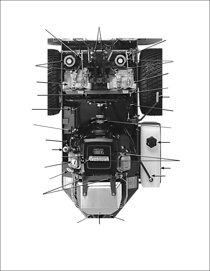
Component Identification
LH Transmission |
Steering Levers |
|
Dampening Springs |
||
Control Arm |
|
|
|
RH Transmission |
|
|
Control Arm |
|
|
RH Transaxle |
|
LH Transaxle |
Expansion |
|
Reservoir |
||
Expansion |
||
and Hose |
||
Reservoir |
||
|
||
and Hose |
RH Transaxle |
|
LH Transaxle |
RH Transaxle |
|
|
Lockout Rod |
|
LH Transaxle |
|
|
Lockout Rod |
Parking Brake |
|
Positive (+) |
Parking Brake |
|
Battery Cable |
Linkage |
|
Negative (-) |
|
|
Battery Cable |
Flexible PTO |
|
|
||
|
Spider Coupling |
|
Fuel Pump |
Fuel Tank Cap |
|
|
||
Fuel Filter |
|
|
Air Cleaner Cover |
Air Cleaner |
|
|
||
|
Cover Latch |
|
Oil Fill |
Fuel Tank |
|
|
Fuel Pickup Line |
|
Oil Dipstick |
|
|
Rubber Bumpers |
|
|
(Body Support) |
|
|
LH Tail Weight |
RH Tail Weight |
|
Muffler Heat Shield |
||
|
||
|
Top View (Body Raised) |
10
Safety Instructions
Pay particular attention to any information labeled
DANGER, WARNING, CAUTION, IMPORTANT, and NOTE in this manual.
When you see the Safety Alert Symbol ( ), read, understand, and follow the instructions. Failure to comply with safety instructions may result in personal injury.
The seriousness or degree of importance of each type of information is defined as follows:
DANGER
An IMMEDIATE hazard that WILL result in severe personal injury or DEATH, if warning is ignored and proper safety precautions are not taken.
WARNING
A POTENTIAL hazard that COULD result in severe personal injury or DEATH, if warning is ignored and proper safety precautions are not taken.
CAUTION
Possible hazards or unsafe practices that MAY result in MODERATE personal injury or property damage, or machine damage, if warning is ignored and proper safety precautions are not taken.
IMPORTANT: Identifies mechanical information demanding special attention, since it deals with the possibility of damaging a part or parts of the machine.
NOTE: Identifies information worthy of special attention.
Walker Manufacturing cannot predict every potentially dangerous situation. Therefore, items labeled as such in this manual do not cover all conceivable situations. Any person using procedures, tools, or control techniques not recommended by Walker Manufacturing must take full responsibility for safety.
The Walker Rider Lawnmower has been designed with many safety features to protect the operator from personal harm or injury. However, it is necessary for the operator to use safe operating procedures at all times. Failure to follow safety instructions contained in this manual may result in personal injury or damage to equipment or property.
If you have any questions concerning setup, operation, maintenance, or safety, please contact your authorized Walker Mower Dealer or call Walker Manufacturing Company at (970) 221-5614.
BEFORE OPERATING
1.Read and understand the contents of this Owner’s Manual before starting and operating the machine. Become thoroughly familiar with all machine controls and how to stop the machine and disengage the controls quickly. Replacement Owner’s Manuals are available by sending the Model and Serial Number to:
Walker Manufacturing Company
5925 East Harmony Road
Fort Collins, CO 80528
2.Never allow children to operate rider mower.
Do not allow adults to operate without proper instruction.
3.Clear the area to be mowed of any foreign objects which may be picked up and thrown by cutter blades. Pick up all sticks, stones, wire, and any other debris.
4.Keep everyone, especially children and pets, a safe distance away from the area being mowed.
Do not mow with bystanders in the area.
5.Do not operate the machine barefoot or wearing sandals, sneakers, tennis shoes, or similar lightweight footwear. Wear substantial protective footwear.
11

Safety Instructions
6.Do not wear loose fitting clothing that could get caught in moving parts. Do not operate this machine while wearing shorts; always wear adequate protective clothing, including long pants. Wearing safety glasses, safety shoes, and a helmet is advisable and required by some local ordinances and insurance regulations.
7.Prolonged exposure to loud noise can cause impairment or loss of hearing. Operator hearing protection is recommended. Wear a suitable hearing protective device, such as earmuffs or earplugs.
8.Keep all protective shields and safety devices in place. If a protective shield, safety device, or decal is damaged, unusable, or missing, repair or replace it before operating the machine.
9.Be sure interlock switches are functioning correctly, so the engine cannot be started unless the Forward Speed Control lever is in the NEUTRAL-PARK position, and the PTO switch is in the DISENGAGED position. Also, the engine should stop if the operator lifts off the seat with the PTO switch in the ENGAGED position.
10.Handle gasoline with care. Gasoline is highly flammable and its vapors are explosive:
a.Use an approved fuel container.
b.Never add fuel to a running engine or hot engine (allow hot engine to cool several minutes).
c.Keep matches, cigarettes, cigars, pipes, open flames, or sparks away from the fuel tank and fuel container.
d.Always fill the fuel tank outdoors using care. Fill to about one inch from the top of the tank. Use a funnel or spout to prevent spilling.
e.Replace the machine fuel cap and container cap securely and clean up any spilled fuel before starting the engine.
11.Never attempt to make any adjustments while the engine is running, except where specifically instructed to do so.
12.The electrical system battery contains sulfuric acid. Avoid any contact with skin, eyes, and clothing. Keep the battery and acid out of reach of children.
OPERATING
1.Operate the mower only in daylight or in good artificial light with good visibility of the area being mowed.
2.Sit on the seat when starting the engine and operating the machine. Keep feet on the deck footrests at all times when the tractor is moving and/or mower blades are operating.
3.For a beginning operator, learn to steer
(maneuver) the tractor with a slow engine speed before attempting any mowing operation. Be aware that, with the front mounted mower configuration, the back of the tractor swings to the outside during turns.
4.Remember, for an emergency stop, the forward motion of the tractor can always be stopped by pulling the Forward Speed Control (FSC) into the NEUTRAL-PARK position.
5.In case the transmission drive belt breaks during operation, and if the machine is on a slope, the machine will freewheel down the slope. To maintain control, immediately (1) Release the steering levers and simultaneously (2) Move the FSC to the NEUTRAL-PARK position. When the machine is stopped or moving slowly, engage the parking brake.
NOTE: This is exactly the same procedure used to normally stop and park the machine.
6.Disengage the blade clutch and put the FSC in the NEUTRAL-PARK position before starting the engine (an ignition interlock switch normally prevents starting of the machine if these controls are in the OPERATING position).
7.Do not run the engine in a confined area without adequate ventilation. Exhaust fumes are hazardous and can be deadly.
8.Do not carry passengers - maximum seating capacity is one (1) person.
12

Safety Instructions
9.Watch for holes, rocks, and roots in the terrain and for other hidden hazards. When mowing tall grass, mow higher than desired to expose any hidden obstacles. Then, clean the area and mow to the desired height.
10.Avoid sudden starts or stops. Before backing the machine up, look to the rear to be sure no one is behind the machine. Watch carefully for traffic when crossing or working near roadways.
11.Disengage the blade drive when transporting the machine across drives, sidewalks, etc. Never raise the mower deck while blades are rotating.
12.The maximum recommended side slope operating angle is 20 degrees or 33% grade.
When operating the machine on a slope, reduce speed and use caution to start, stop, and maneuver. To prevent tipping or loss of control of the machine, avoid sharp turns or sudden changes in direction.
13.Never adjust cutting height with the engine running. Before adjusting cutting height or servicing, disengage the blade clutch (PTO), stop the engine, and remove the ignition key. Wait for all movement to stop before getting off the seat.
NOTE: The electric clutch brake should normally stop drive line rotation within five (5) seconds of disengaging the PTO clutch.
14.For side discharge mower decks, do not operate with the grass deflector chute removed.
Keep the deflector in the lowest possible position.
15.When using the tilt-up deck, observe the following recommendations:
a.Do not move tractor with deck in tilt-up position.
b.Never tilt body forward with deck in tilt-up position.
16.In case of a clogged or plugged mower deck:
a.Disengage the blade clutch (PTO) and turn the engine off before leaving the seat.
b.LOOK to make sure blade drive shaft movement has stopped before trying to unclog the system.
c.Disconnect the spark plug wires.
d.Never place hands under the deck use a stick or similar tool to remove clogged material.
17.If the cutting blades strike a solid object or the machine begins to vibrate abnormally, immediately disengage the blade clutch (PTO), stop the engine, and wait for all moving parts to stop. To prevent accidental starting, disconnect the spark plug wires. Thoroughly inspect the mower and repair any damage before restarting the engine and operating the mower. Make sure cutter blades
are in good condition and blade nuts are torqued to 60 ft-lb (81.3 N m).
18.Do not touch the engine or muffler while the engine is running or immediately after stopping the engine. These areas may be hot enough to cause serious burns.
19.When leaving the machine unattended, disengage the blade clutch (PTO), stop the engine, and remove the key.
MAINTENANCE
1.To prevent accidental starting of the engine when servicing or adjusting the machine, remove the key from the ignition switch and disconnect the spark plug wires.
2.To reduce fire hazards, keep the engine free of grass, leaves, excessive grease, and dirt.
3.Keep all nuts, bolts, and screws tight to ensure the machine is in a safe, working condition. Check the blade mounting nuts frequently, making sure they are tight.
4.Perform only maintenance instructions described in this manual. Unauthorized maintenance operations or machine modifications may result in unsafe operating conditions.
13

Safety Instructions
5.If the engine must be running to perform a maintenance adjustment, keep hands, feet, and clothing away from moving parts. Do not wear jewelry or loose clothing.
6.Always use the proper engine service manual when working on the engine.
Unauthorized maintenance operations or modifications to the engine may result in unsafe operating conditions.
7.Altering the equipment or engine in any manner which adversely affects its operation, performance, durability, or use will VOID the warranty and may cause hazardous conditions.
8.Never attempt to disconnect any safety devices or defeat the purpose of these safety devices.
9.Do not change the engine governor settings or overspeed the engine. The governor has been factory-set for maximum-safe engine operating speed.
10.Use genuine factory replacement parts. Substitute parts may result in product malfunction and possible injury to the operator and/or others.
11.Use care when charging the battery or performing maintenance on the battery and electrical system:
a.Make sure the battery charger is unplugged before connecting or disconnecting cables to the battery.
b.Charge the battery in a well-ventilated space, so gases produced while charging can dissipate. Make sure the battery vents in the caps are open.
c.Keep sparks, flames, and smoking materials away from the battery at all times. To avoid sparks, use care when removing battery cables from posts.
d.Disconnect both battery cables before unplugging any wiring connectors or making repairs on the electrical system.
IMPORTANT: Keep all applicable manuals immediately accessible to anyone who may operate or service this machine.
14

Safety Instructions
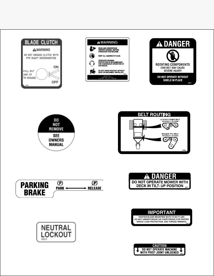
SAFETY, CONTROL, AND INSTRUCTION DECALS
Safety, Control, and Instruction Decals are installed on the machine;
if any are missing, illegible, or damaged, a replacement should be ordered and installed before putting the machine into operation. The Decal Part Number is listed below and in the Parts Section.
Each End of Mower Deck (5808)
SD Deck Discharge Shield (5848)
LH Fender (5802-2) |
RH Fender (5802-1) |
Rear Body,
Above Muffler (5805)
Deck Gearbox Cover (5807-3)
15
Safety Instructions
SAFETY, CONTROL, AND INSTRUCTION DECALS
Safety, Control, and Instruction Decals are installed on the machine;
if any are missing, illegible, or damaged, a replacement should be ordered and installed before putting the machine into operation. The Decal Part Number is listed below and in the Parts Section.
Front Body Adjacent to
LH Steering Lever (7818)
Blade Clutch on Front Body Adjacent to RH Steering Lever (6806)
Hydrostat Oil
Reservoir (4024-2)
Parking Brake (4406-8)
Center Body Behind Transaxles
(9804)
Upper Guard
(4107-1)
Belt Routing (4107-4)
Deck Carrier Frame (8647)
Deck Carrier Frame (5865)
Deck Carrier Frame (8653)
16
Assembly Instructions
SETUP INSTRUCTIONS
Walker Mowers are shipped partially assembled to our distribution network, and are typically assembled by the selling dealer. For any additional assembly besides the following, contact your Walker dealer.
Battery Service
The battery is a completely sealed, non serviceable battery.
IMPORTANT: Make sure battery is securely mounted in the frame. A loose battery may cause damage to the case resulting in acid leakage and severe damage to the machine. A hazard may be created by damage to critical working parts and safety systems.
Mower Deck Assembly
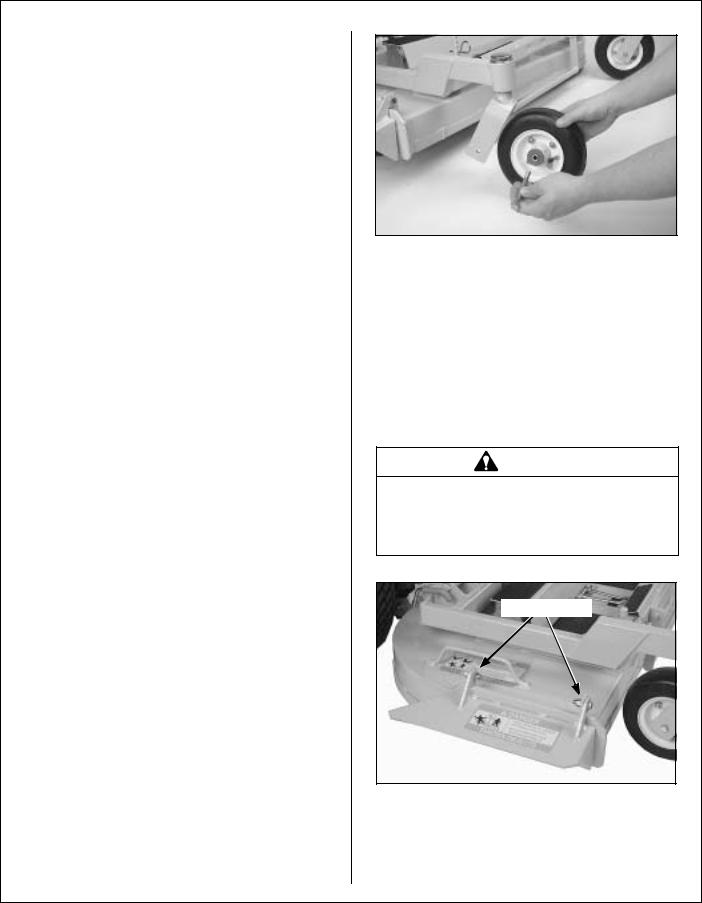
Deck Caster Wheels Installation
1.Remove the bolt, nut, axle spacer tube, and spacer washers from each deck caster wheel fork.
NOTE: Spacer washers are used only when the optional semi-pneumatic deck wheels (8.25 x 2.75) are installed.
2.Fit the axle spacer tube through the wheel hub, position the spacer washer on each side of the hub (if used), and fit the assembly into the wheel fork.
3.Insert the 3/8-16 x 4-1/2 in. bolt through the wheel fork with the bolt head to the outside and install the 3/8-16 in. Keps nut.
4.Tighten the bolt and nut until the axle spacer tube bottoms against the inside of the wheel fork (will not turn) while the wheel and spacer washers (if used) spin freely without binding.
Deck Caster Wheel Installation
Deck Discharge Shield Installation
(Side Discharge Models Only)
Attach the deck side discharge shield by positioning the shield hinge lug in front of the deck mount and fastening with two 3/8-16 x 1-1/4 in. bolts, 3/8-16 ESNA nuts, and 3/8 in. wave spring washers. The wave washers fit between the two hinging surfaces. Tighten the nuts until the shield moves freely but is not loose.
WARNING
DO NOT operate the machine without the grass deflector chute attached and in the lowest possible position.
Attach Shield
Deck Discharge Shield Installation
17
Assembly Instructions
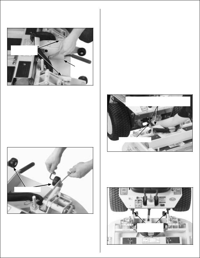
PTO Shaft Guard Installation
Position the shaft guard as shown and mount with two 1/4-20 x 1/2 in. bolts.
Carrier Frame
Tube Sockets
Attach
Guard
PTO Shaft Guard Installation
Tilt-Up Roller Wheel Installation
NOTE: A 2-1/2" diameter tilt-up roller wheel
(P/N 9772) is required for decks installed on the Model MB tractor.
Mount the two (2) tilt-up roller wheels on the brackets on the rear skirt of the deck housing using the P/N 8490 axle bolt, 3/8 in. wave spring washer and 3/8-16 in. Whiz locknut. Tighten the axle bolt until the wheel rolls freely, but is not loose.
Roller Wheels
Roller Wheel Installation
Mower Deck Installation on Tractor
Deck Installation
1.Lightly grease each deck support arm (2) on the tractor. Refer to Mower Deck Installation photo for location of deck support arm.
2.Engage the deck carrier frame tube sockets on the tractor support arms (refer to PTO Shaft Guard Installation photo for socket location). Slide the deck onto the support arms approximately 3 in. (76 mm).
3.Align and connect the splined PTO shaft and socket halves, as shown in PTO Shaft Connection photo. The PTO shaft has a pilot end to ease alignment of shaft; fit shaft end into socket and rotate shaft until the splines line up as indicated by arrows, then slide together.
Arrows on Shaft and Tube (used to align when sliding together)
PTO Connection
PTO Shaft Connection
4.Install the hitch pin through the hole on the end of each support arm to lock the deck in place (refer to Deck Counterweight Spring Installation photo). Two (2) hitch pins are included in the owner’s packet of materials.
Deck Support
Arms
Mower Deck Installation
18
Assembly Instructions
Spring Tension Adjustment Nut
Located Under Lower
Spring Hook (not visible)
Counterweight Springs
Clip Onto Body
With Body Tilted Up
Hitch Pins
Lock Deck On
Support Arms
Deck Counterweight Spring Installation
5.Raise mower body (instead of lifting the front of deck) and clip the counterweight springs to the receptacle on front of body. Lower the body to tension the springs. (Refer to Deck Counterweight Spring Installation photo.)
6.With the counterweight springs connected, the weight on the deck caster wheels should be 15 to 25 Ib (6.8 to 11.3 kg). Check this weight by lifting on the front of the deck carrier frame. If required, the spring tension can be adjusted by tightening or loosening the elastic stop nuts located underneath the lower spring hook. Refer to Deck Counterweight Spring Installation photo.
19
Assembly Instructions
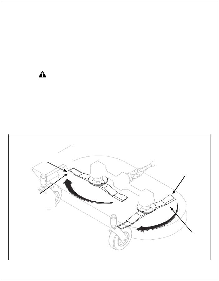
Deck Leveling |
|
2. |
Check the side-to-side level. Rotate each blade |
|
|
|
sideways and measure the distance from blade |
1. Position mower on a smooth, level surface. Set |
|
|
tip to ground on each side. If measurements |
the cutting height to the highest position - 4 in. |
|
|
vary more than 1/8 in. (3 mm), add a washer |
(102 mm) - for easy access under the deck to |
|
|
shim under the deck support pins on the low side |
measure blade height. Refer to ADJUSTING |
|
|
to level the deck. |
CUTTING HEIGHT in Operating Instructions. |
|
3. |
Check the front-to-rear level. Rotate the blades |
|
|
||
NOTE: A block of wood cut 4 in. (102 mm) high |
|
|
to point forward. Measure the distance from |
is a convenient gauge to measure blade height |
|
|
blade tip to ground on the front and rear. The |
above ground during the leveling process. |
|
|
rear of the blade should be 1/8 to 1/4 in. (3 to 6 |
|
|
|
mm) higher than the front of the blade; shim the |
|
|
|
rear (or front) deck support pins equally to |
WARNING |
|
|
|
|
|
achieve at least 1/8 in. (3 mm) difference. |
|
|
|
|
NOTE: The mower deck and support frame |
The machine must be shut off during this |
|
|
|
|
|
are jig welded; within normal tolerances, very lit- |
|
procedure. |
|
|
|
|
|
tle, if any, shimming should be required to level |
|
|
|
|
|
|
|
|
the deck. Tire pressure will influence the level- |
|
|
|
|
|
|
|
ness of the deck. Check the tire pressure as a |
|
|
|
possible cause of the deck not being level. |
|
|
|
|
4 in. (102 mm) Wood Block
Should be 1/8 in. (3 mm) to 1/4 in. (6 mm) higher at the rear of the blade
Should not vary more than 1/8 in. (3 mm) side-to-side
4 in. (102 mm) Wood Block
Deck Leveling
20
 Loading...