


SERVICE MANUAL
C24GA SERIES
CONVECTION
STEAMERS
MODELS
C24GA6 ML-136021
C24GA10 ML-136022
- NOTICE -
This manual is prepared for the use of trained Vulcan Service Technicians and should not be used by those not properly qualified. If you have attended a Vulcan Service School for this product, you may be qualified to perform all the procedures described in this manual.
This manual is not intended to be all encompassing. If you have not attended a Vulcan Service School for this product, you should read, in its entirety, the repair procedure you wish to perform to determine if you have the necessary tools, instruments and skills required to perform the procedure. Procedures for which you do not have the necessary tools, instruments and skills should be performed by a trained Vulcan Service Technician.
Reproduction or other use of this Manual, without the express written consent of Vulcan, is prohibited.
For additional information on Vulcan-Hart or to locate an authorized parts and service provider in your area, visit our website at www.vulcanhart.com
VULCAN-HART |
3600 NORTH POINT BLVD. |
DIVISION OF ITW FOOD EQUIPMENT GROUP, LLC |
BALTIMORE, MD 21222 |
WWW.VULCANHART.COM |
F35425(February2006) |

C24GA SERIES CONVECTION STEAMERS |
|
TABLE OF CONTENTS |
|
GENERAL................................................................................................................................................................ |
4 |
Introduction ....................................................................................................................................................... |
4 |
Installation ........................................................................................................................................................ |
4 |
Operation .......................................................................................................................................................... |
4 |
Cleaning .......................................................................................................................................................... |
4 |
Specifications ................................................................................................................................................... |
4 |
Gas Line Pressures .................................................................................................................................. |
4 |
Burner Pressure ........................................................................................................................................ |
4 |
Electrical ................................................................................................................................................... |
4 |
Water Supply ............................................................................................................................................ |
4 |
Tools ................................................................................................................................................................. |
4 |
Standard ................................................................................................................................................... |
4 |
Special ...................................................................................................................................................... |
4 |
REMOVALAND REPLACEMENT OF PARTS .......................................................................................................... |
5 |
Covers and Panels ............................................................................................................................................ |
5 |
Cooking Compartment Right Side Panel.................................................................................................... |
5 |
Cooking Compartment Flue Wrap ............................................................................................................. |
5 |
Cooking Compartment Left Side Panel ...................................................................................................... |
5 |
Cabinet Base Right Side Panel ................................................................................................................. |
5 |
Cabinet Base Left Side Panel .................................................................................................................... |
6 |
Cabinet Base Front Panel ......................................................................................................................... |
6 |
Cabinet Base Rear Panel .......................................................................................................................... |
6 |
Cooking Compartment Door .............................................................................................................................. |
6 |
Door Assembly .......................................................................................................................................... |
6 |
Door Gasket .............................................................................................................................................. |
7 |
Door Handle .............................................................................................................................................. |
7 |
Door Latch Assembly ................................................................................................................................ |
8 |
Compartment Controls ...................................................................................................................................... |
8 |
Main Burner ...................................................................................................................................................... |
9 |
Gas Combination Control Valve ......................................................................................................................... |
9 |
GeneratorAssembly ......................................................................................................................................... |
9 |
Fill and Cold Water Solenoid Valves ................................................................................................................ |
11 |
Pilot Spark/Probe Flame Sensor ..................................................................................................................... |
12 |
SERVICE PROCEDURES AND ADJUSTMENTS ................................................................................................... |
13 |
Blower Air Pressure Adjustment ...................................................................................................................... |
13 |
Air Pressure Switch Adjustment ..................................................................................................................... |
13 |
Pilot Burner Adjustment .................................................................................................................................. |
14 |
Operating Pressure Switch ...................................................................................................................... |
15 |
Thumb Wheel Adjustment ....................................................................................................................... |
16 |
Inlet Water/Steam Strainer ...................................................................................................................... |
16 |
Automatic Ignition Systems ............................................................................................................................ |
17 |
Spark Ignition Control Test ....................................................................................................................... |
17 |
Ignition Test .................................................................................................................................................... |
18 |
Manifold Pressure Adjustment ........................................................................................................................ |
18 |
Cooking Compartment .................................................................................................................................... |
19 |
Controls .................................................................................................................................................. |
19 |
Door ............................................................................................................................................................... |
19 |
Latch Adjustment .................................................................................................................................... |
19 |
Striker Adjustment ................................................................................................................................... |
20 |
Deliming the Generator ................................................................................................................................... |
20 |
Cooking Cycle Test ......................................................................................................................................... |
21 |
General ................................................................................................................................................... |
21 |
Probe Inspection ............................................................................................................................................. |
21 |
F35425 (February 2006) |
|
Page 2 of 40 |
|

C24GA SERIES CONVECTION STEAMERS |
|
ELECTRICALOPERATION .................................................................................................................................... |
22 |
Water Level Controls ...................................................................................................................................... |
22 |
Low Level Cut-Off & Differential Control .................................................................................................... |
22 |
Sequence of Operation ................................................................................................................................... |
22 |
Initial Fill and Preheat Conditions ............................................................................................................ |
22 |
Schematics .................................................................................................................................................... |
25 |
Component Location Cabinet Base Generator ................................................................................................ |
28 |
Component Function Cabinet Base Generator ................................................................................................ |
29 |
Component Location Cooking Compartment ................................................................................................... |
31 |
Component Function Cooking Compartment ................................................................................................... |
32 |
General ................................................................................................................................................... |
32 |
TROUBLESHOOTING ............................................................................................................................................ |
33 |
General ................................................................................................................................................... |
33 |
Water Not Being Supplied to Generator ................................................................................................... |
33 |
Pilot Or Main Burner Will Not Light .......................................................................................................... |
33 |
Drain Solenoid Valve Does Not Drain ....................................................................................................... |
33 |
Water Accumulating in Compartment ...................................................................................................... |
33 |
Cooking Cycle Cannot be Activated ......................................................................................................... |
33 |
Steamer Achieves Pressure Slower Than Normal .................................................................................... |
33 |
Troubleshooting Sequence Of Operation ......................................................................................................... |
34 |
TROUBLESHOOTING CHART................................................................................................................................ |
35 |
CONDENSED SPARE PARTS LIST ....................................................................................................................... |
38 |
©VULCAN 2005 |
|
Page 3 of 40 |
|
F35425 (February 2006) |
|

C24GA SERIES CONVECTION STEAMERS - GENERAL
GENERAL
INTRODUCTION
Procedures in this manual will apply to all models unless specified. Pictures and illustrations can be of any model unless the picture or illustration needs to be model specific.
INSTALLATION
Refer to the Installation and Operation Manual for detailed installation instructions on steamers.
OPERATION
Refer to the Installation and Operation Manual for specific operating instructions.
CLEANING
Refer to the Installation and Operation Manual for specific cleaning instructions.
SPECIFICATIONS
Gas Line Pressures
•Operating Pressure
Natural - Recommended 2.5” W.C. Propane - Recommended 10.0” W.C.
•Incoming Pressure
Natural - Recommended 7.0” W.C. min. Propane - Recommended 11.0” W.C. min.
Burner Air Pressure
0.4” W.C.
Electrical
Voltage: 120/60/1
Amps: 2.5 Amps Frequency: 50/60 Hz
Water Supply
Supply pressure: 20-60 psig Hardness*: Less than 3 grains Silica: Less than 13 ppm
Total Chloride: Less than 4.0 ppm pH Range: 7 to 8
Undissolved Solids: Less than 5 microns (*17.1 ppm = 1 grain of hardness)
TOOLS
Standard
•Standard set of hand tools.
•VOM with A.C. current tester (Any quality VOM with a sensitivity of at lease 20,000 ohms per volt can be used.)
Special
•Gas leak detection equipment.
•Gas Manometer.
•Loctite 271
•Screwdriver, 1/8 X 4 cabinet tip
F35425 (February 2006) |
|
Page 4 of 40 |
|
C24GA SERIES CONVECTION STEAMERS - REMOVALAND REPLACEMENT OF PARTS
REMOVAL AND REPLACEMENT OF PARTS
COVERS AND PANELS
WARNING: DISCONNECT THE
ELECTRICAL POWER TO THE
MACHINE AND FOLLOW LOCKOUT /
TAGOUT PROCEDURES.
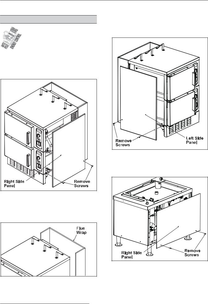
Cooking Compartment Right Side Panel
1.Remove the screws then remove the right side panel from the compartment.
Cooking Compartment Flue Wrap
1.Remove left and right side panels from compartment. Remove screws that secure flue wrap.
Cooking Compartment Left Side Panel
1.Remove the screws then remove the left side panel from the compartment.
Cabinet Base Right Side Panel
1.Remove the screws then remove the right side panel from the cabinet base.
Page 5 of 40 |
|
F35425 (February 2006) |
|
C24GA SERIES CONVECTION STEAMERS - REMOVALAND REPLACEMENT OF PARTS
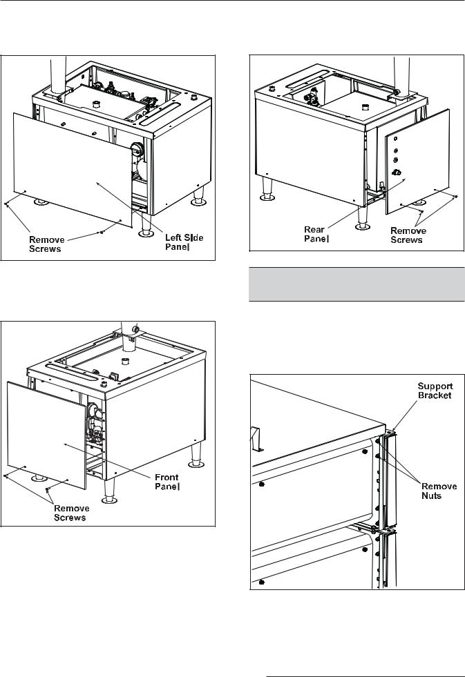
Cabinet Base Left Side Panel
1.Remove the screws then remove the left side panel from the cabinet base.
Cabinet Base Rear Panel
1.Remove the screws then remove the rear panel from the cabinet base.
Cabinet Base Front Panel
1.Remove the screws then remove the front panel from the cabinet base.
COOKING COMPARTMENT |
DOOR |
Door Assembly
1.Remove compartment left side panel as outlined under COVERS AND PANELS.
2.Remove nuts from top door support bracket.
3.Open the door and lift from bottom hinge.
4.Reverse the procedure to install and check for proper operation.
F35425 (February 2006) |
|
Page 6 of 40 |
|
C24GA SERIES CONVECTION STEAMERS - REMOVALAND REPLACEMENT OF PARTS
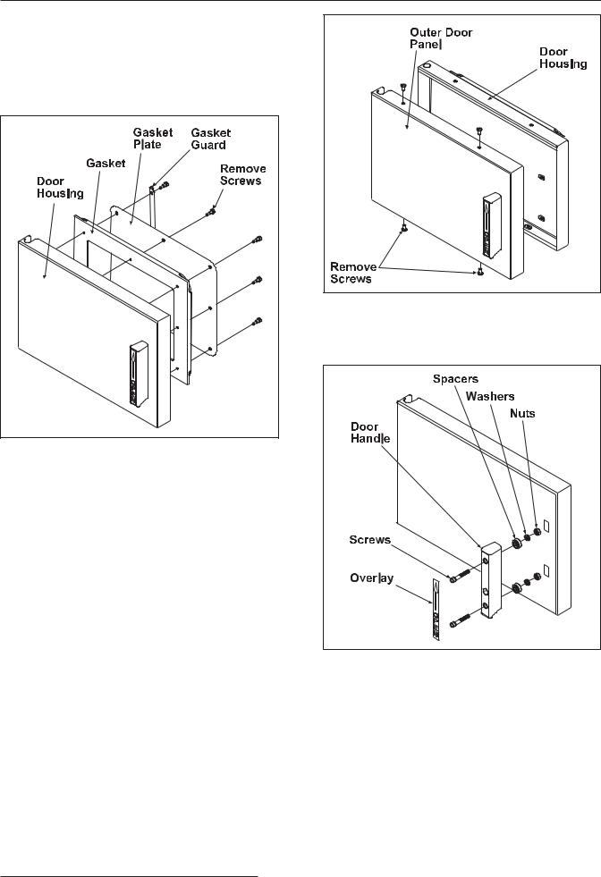
Door Gasket
1.Open the door.
2.Remove screws from the gasket guard and gasket plate.
3.Remove the gasket guard and the gasket plate.
4.Position the new gasket on the gasket plate.
5.Reverse the procedure to install.
6.Adjust the door as outlined under SERVICE PROCEDURESANDADJUSTMENTS.
Damage to the gasket sealing surface, such as nicks or cuts, will cause steam leakage.
Door Handle
1.Open the door.
2.Remove screws from the top and bottom of the door.
3.Pull the outer door panel out from the door housing.
4.Remove the plate, nuts, washers and spacers from the handle screws and remove the door handle from the door.
5.Reverse procedure to install. When installing the spacers, the smaller diameter fits into the slot in the door and the latch. Use Loctite 271 to secure fasteners.
Page 7 of 40 |
|
F35425 (February 2006) |
|
C24GA SERIES CONVECTION STEAMERS - REMOVALAND REPLACEMENT OF PARTS
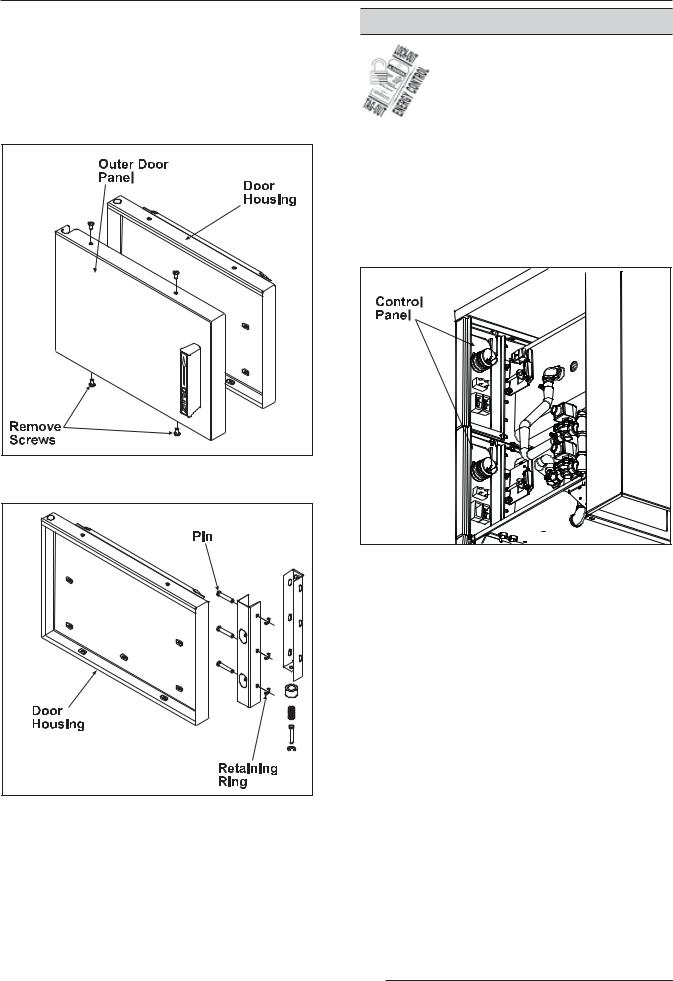
Door Latch Assembly
1.Open the door.
2.Remove screws from the top and bottom of the door.
3.Pull the outer door panel out from the door housing.
COMPARTMENT CONTROLS
WARNING: DISCONNECT THE
ELECTRICAL POWER TO THE
MACHINE AND FOLLOW LOCKOUT /
TAGOUT PROCEDURES.
1.Remove compartment right side cover as outlined under COVERS AND PANELS.
2.Remove the component being replaced.
3.Reverse the procedure to install the replacement component, then check steamer for proper operation.
4.Remove the pins and retaining rings.
5.Remove the latch assembly from the door.
6.Reverse procedure to install. Use Loctite 271 to secure fasteners.
F35425 (February 2006) |
|
Page 8 of 40 |
|
C24GA SERIES CONVECTION STEAMERS - REMOVALAND REPLACEMENT OF PARTS
MAIN BURNER
WARNING: DISCONNECT THE
ELECTRICAL POWER TO THE
MACHINE AND FOLLOW LOCKOUT /
TAGOUT PROCEDURES.
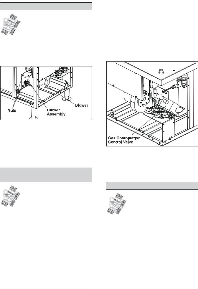
1.Remove front and side covers as outlined under COVERS AND PANELS.
2.Disconnect the gas line at gas combination control valve.
3.Disconnect wires to burner assembly.
4.Remove the nuts securing burner to tank.
5.Drop blower end of burner assembly slightly down to clear control box and push all interfering wires out of the way so that burner can be pulled out of tank.
6.Reverse procedure to install burner assembly.
GAS COMBINATION
CONTROL VALVE
WARNING: DISCONNECT THE
ELECTRICAL POWER TO THE
MACHINE AND FOLLOW LOCKOUT /
TAGOUT PROCEDURES.
WARNING: SHUT OFF THE GAS SUPPLY BEFORE SERVICING THE UNIT.
WARNING: ALL GAS JOINTS DISTURBED DURING SERVICING MUST BE CHECKED FOR LEAKS. CHECK WITH A SOAP AND WATER SOLUTION (BUBBLES). DO NOT USE AN OPEN FLAME.
A.CHECK ALL JOINTS PRIOR TO THE GAS VALVE (SOLENOID) BEFORE LIGHTING THE UNIT.
B.CHECK ALL JOINTS BEYOND GAS VALVE (SOLENOID) AFTER UNIT IS LIT.
Gas combination control valves are not serviceable and should not be disassembled. Once the problem has been isolated to this control, replace it. Do not attempt to repair the assembly.
1.Remove the front and right side panels as outlined under COVERS AND PANELS.
2.Remove main burner as outlined in MAIN BURNER.
3.Disconnect electrical supply wires running to the gas combination control valve.
4.Disconnect the pilot gas supply tube from the control and pipe connections on each side of the gas combination control valve.
5.Reverse procedure to install and check unit for proper operation.
GENERATOR ASSEMBLY
WARNING: DISCONNECT THE
ELECTRICAL POWER TO THE
MACHINE AND FOLLOW LOCKOUT /
TAGOUT PROCEDURES.
WARNING: SHUT OFF THE GAS SUPPLY BEFORE SERVICING THE UNIT.
WARNING: ALL GAS JOINTS DISTURBED DURING SERVICING MUST BE CHECKED FOR LEAKS. CHECK WITH A SOAP AND WATER SOLUTION (BUBBLES). DO NOT USE AN OPEN FLAME.
A.CHECK ALL JOINTS PRIOR TO THE GAS VALVE (SOLENOID) BEFORE LIGHTING THE UNIT.
B.CHECK ALL JOINTS BEYOND GAS VALVE (SOLENOID) AFTER UNIT IS LIT.
Page 9 of 40 |
|
F35425 (February 2006) |
|
C24GA SERIES CONVECTION STEAMERS - REMOVALAND REPLACEMENT OF PARTS
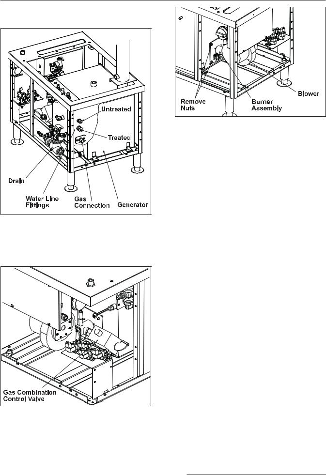
1.Drain the generator and allow steamer to cool, if necessary.
2.Remove rear and side panels as outlined under COVERS AND PANELS.
3.Disconnect gas line at gas combination control valve.
4.Disconnect wires to burner assembly.
5.Disconnect wires from gas combination control valve.
6.Remove the nuts securing the burner to generator.
7.Drop blower end of burner assembly slightly down to clear control box and push all wires out of the way so that burner can be pulled out of tank.
8.Disconnect wires from the 195°F thermostat mounted to the generator and operating pressure switch.
9.Loosen hose clamp attaching lower flexible water line at back panel and use a wrench to disconnect barb fitting from main inlet water connection.
10.Loosen hose clamp attaching upper flexible water line at back panel and use a wrench to disconnect barb fitting from main inlet water connection.
11.Remove water line from generator. Remove steam hoses from steam trap and supply to super heater.
12.Disconnect gas tubing from rear panel
13.Remove steel drain tube at tank.
14.Disconnect union between tank and drain.
15.Loosen cable clamp screws securing electrical cable at rear panel so that cable is free to move.
16.Remove screws to free super heater and lift super heater off flue pipe.
F35425 (February 2006) |
|
Page 10 of 40 |
|

C24GA SERIES CONVECTION STEAMERS - REMOVALAND REPLACEMENT OF PARTS
16.Rotate pressure relief valve coupling to allow pressure relief valve to be rotated about 90° so that valve is below generator top level.
17.Remove pressure switch from generator.
19.Move any interfering components out of the way, then push generator slightly forward to disengage feet and remove generator from rear of cabinet.
20.Reverse procedure to install generator.
FILL AND COLD WATER
SOLENOID VALVES
WARNING: DISCONNECT THE
ELECTRICAL POWER TO THE
MACHINE AND FOLLOW LOCKOUT /
TAGOUT PROCEDURES.
1.Turn off the water supply to the steamer.
2.Remove front and side covers as outlined under COVERS AND PANELS.
18. Remove bolts attaching front of generator to frame.
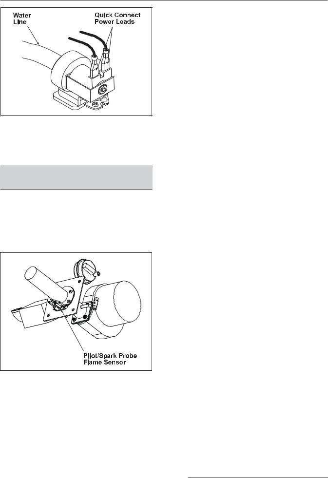
3. Pull the quick connect power leads off the solenoid valve being serviced.
Page 11 of 40 |
|
F35425 (February 2006) |
|
C24GA SERIES CONVECTION STEAMERS - REMOVALAND REPLACEMENT OF PARTS
4.Disconnect the water lines for the solenoid valve being serviced and remove the solenoid valve from the unit.
5.Reverse procedure to install solenoid valve.
PILOT/SPARK PROBE
FLAME SENSOR
1.Removemainburnerassemblyasoutlinedunder MAINBURNERin REMOVALANDREPLACEMENT OF PARTS.
2.Remove the pilot assembly by disconnecting gas tube to the pilot burner and remove screws holding pilot assembly.
3.Replace the malfunctioning flame sensor or pilot assembly.
4.Reverse procedure to install a new flame sensor or pilot assembly.
5.Check for proper operation.
F35425 (February 2006) |
|
Page 12 of 40 |
|
 Loading...