


VR-6000
OWNER©S MANUAL
MANUEL D©INSTRUCTIONS
MANUAL DE INSTRUCCIONES
VER 5 JAN 2005
842-410-000

INSTRUCTIONS MANUAL

INSTRUCTIONS MANUAL
INDEX |
|
INDEX............................................................................................................................................................................................................. |
3 |
SAFETYSUMMARY............................................................................................................................................................................ |
4 |
SAFETY INFORMATION......................................................................................................................................................... |
4 |
ELECTRICAL SHOCK HAZARDS |
5 |
MOTIONHAZARDS |
5 |
FUME HAZARDS |
5 |
HEAT/FREEZING HAZARDS |
6 |
EXPLOSION/FLAMEHAZARDS |
6 |
ADDITIONAL SAFETY INFORMATION........................................................................................................................ |
6 |
INTRODUCTION.................................................................................................................................................................................. |
7 |
GENERAL........................................................................................................................................................................................... |
7 |
CERTIFICATION........................................................................................................................................................................... |
7 |
ABOUT THIS MANUAL............................................................................................................................................................. |
7 |
ABOUT THE VIPER A/C AIR CONDITIONING SERVICE CENTER........................................................ |
7 |
THE MACHINE....................................................................................................................................................................................... |
8 |
BASIC COMPONENTS............................................................................................................................................................ |
8 |
CONTROLS AND CONTROL SYSTEM................................................................................................................... |
10 |
FUNCTION SELECTOR KEYBOARD......................................................................................................................... |
11 |
STATUS AND ALARM PANEL.......................................................................................................................................... |
12 |
MEASUREMENT SETTING................................................................................................................................................ |
13 |
VIPER VR-6000 SPECIFICATIONS.............................................................................................................................. |
13 |
PREPARATION FOR USE........................................................................................................................................................ |
13 |
GENERAL........................................................................................................................................................................................ |
13 |
PREPARATION........................................................................................................................................................................... |
13 |
PREPARE THE REFRIGERANT STORAGE TANK.......................................................................................... |
14 |
TRANSFER NEW REFRIGERANT TO THE STORAGE TANK............................................................... |
14 |
OPERATION INSTRUCTIONS............................................................................................................................................. |
16 |
RECOVER AND RECYCLE REFRIGERANT FROM AN AC SYSTEM............................................... |
16 |
REMOVING NON-CONDENSABLE GASES......................................................................................................... |
16 |
VACUUM PHASE........................................................................................................................................................................ |
18 |
RECHARGE AN A/C SYSTEM......................................................................................................................................... |
18 |
3

INSTRUCTIONS MANUAL |
|
RECOVERING THE REFRIGERANT IN THE HOSES................................................................................... |
19 |
MAINTENANCE.................................................................................................................................................................................. |
20 |
REPLACING REFRIGERANT FILTER/DRYER................................................................................................... |
20 |
EMPTYING THE USED OIL TANK................................................................................................................................ |
21 |
CASE CARE................................................................................................................................................................................... |
21 |
AIR CONDITIONING HOSE MAINTENANCE....................................................................................................... |
21 |
CALIBRATING THE ELECTRONIC SCALE............................................................................................................ |
21 |
VACUUM PUMP........................................................................................................................................................................... |
22 |
M.1) Oil top-up |
22 |
M.2) Oil change |
22 |
M.3) Decontamination |
23 |
TROUBLESHOOTING........................................................................................................................................................... |
24 |
RECOVERY PROBLEMS |
24 |
NO DISPLAY WHEN MAIN POWER SWITCHIS ON |
24 |
REFILLING DOES NOTFLOW |
24 |
MANUFACTURER’S LIMITED WARRANTY............................................................................................................. |
25 |
SAFETY SUMMARY
Congratulations on the purchase of your new VIPER VR-6000 Air Conditioning Service Center. The following safety information is provided as guidelines to help you operate your new system under the safest possible conditions. Any equipment that uses chemicals can be potentiallydangerous to use when safety or safe handling instructions are not known or not followed. The following safety instructions are to provide the user with the information necessary for safe use and operation. Please read and retain these instructions for the continued safe use of your service system.
SAFETY INFORMATION
Every craftsman respects the tools with which they work. They know that the tools represent years of constantly improved designs and developments. The true craftsman also knows that tools are dangerous if misused or abused. To reduce risk of discomfort, illness or even death, read, understand and follow the following safetyinstructions. In addition, make certain that anyone else that uses this equipment, understands and follows these safety instructions as well.
4

INSTRUCTIONS MANUAL
READ ALL SAFETY INFORMATION CAREFULLY before attempting to install, operate or service this equipment. Failure to comply with these instructions could result in personal injuryand/or property damage.
RETAIN THE FOLLOWING SAFETYINFORMATION FOR FUTURE REFERENCE. Published standards on safetyare available. They are listed in ADDITIONAL SAFETY INFORMATION at the end of this SAFETYSUMMARY.
The National Electrical Code, Occupational Safetyand Health Act regulations, local industrial codes and local inspection requirements also provide a basis for equipment installation, use and service.
•The following safety alert symbols identify important safety messages in this manual.
•When you see one of the symbols shown here, be alert to the possibility of personal injuryand carefully read the message that follows.
ELECTRICAL SHOCK HAZARDS
WARNING:
• To reduce the risk of electric shock, unplug the air service center from the outlet before attempting anymaintenance or cleaning. Turning off controls will not reduce this risk.
•Do not operate the VR-6000 with a damaged cord or plug — replace the cord or plug immediately. To reduce the risk of damage to electric plug and cord, disconnect charger bypulling on the plug rather than the cord.
•An extension cord should not be used unless absolutely necessary. Use of an improper extension cord could result in a risk of fire and electric shock. If extension cord must be used, make sure:
a.That pins on plug of extension cord are the same number, size, and shape as those on plug on recycler.
b.That extension cord is properly wired and in good electrical condition; and
c.That the wire size is large enough for the length of cord as specified below:
Length of cord in feet: |
25 |
50 |
100 |
150 |
AWG size of cord: |
16 |
12 |
10 |
8 |
MOTION HAZARDS
WARNING:
• Engine parts that are in motion and unexpected movement of a vehicle can injure or kill. When working near moving engine part, wear snug fit clothing and keep hands and fingers away from moving parts. Keep hoses and tools clear of moving parts. Always stay clear of moving engine parts. Hoses and
tools can be thrown through the air if not kept clear of moving engine parts.
•The unexpected movement of a vehicle can injure or kill. When working on a vehicle, always set the parking brake or block the wheels of the vehicle being serviced.
FUME HAZARDS
WARNING:
• FUMES, GASES, AND VAPORS CAN CAUSE DISCOMFORT, ILLNESS, AND DEATH! To reduce the risk of discomfort, illness, or death, read, understand, and follow the following safety instructions. In addition, make certain that
5

INSTRUCTIONS MANUAL
anyone else that uses this equipment, understands and follows these safety instructions as well.
•Avoid breathing AC refrigerant and lubricant vapor mist. Exposure may irritate eyes, nose, and throat. To remove HFC-134a from the AC system, use service equipment certified to meet the requirements of SAE J2210 (HFC-134a recycling equipment).
•Additional health and safety information may be obtained from additional refrigerant and lubricant manufacturers.
•Always perform vehicle service in a properly ventilated area. Never run an engine without proper ventilation for its exhaust.
•Stop the recycling process if you develop momentary eye, nose, or throat irritation as this indicates inadequate ventilation. Stop work and take necessary steps to improve ventilation in the work area.
HEAT/FREEZING HAZARDS
WARNING:
• When under pressure, refrigerants become liquid. When accidentally released from the liquid state they evaporate and become gaseous. As they evaporate, they can freeze or frostbite tissue very rapidly. When these gases are breathed, the lungs can be seriously damaged. If sufficient quantities are
taken into the lungs, death can result. If you believe you have exposed your lungs to released refrigerant, seek immediate medical assistance.
•Refrigerants can cause frostbite and severe burns to exposed skin. Refrigerants are under pressure and can be forcibly sprayed in all directions if carelessly handled. Avoid contact with refrigerants and always wear hand coverings and make certain other exposed skin is properly covered.
•Refrigerants can also severely injure or cause permanent blindness to unprotected eyes. Refrigerants are under pressure and can be forcibly sprayed in all directions if carelesslyhandled. Avoid contact with refrigerants and always wear safetygoggles.
EXPLOSION/FLAME HAZARDS
WARNING:
• Never recover anything other than the approved refrigerants as specified on the VR-6000. Alternate refrigerants may contain flammables such as butane or propane and can explode or cause a fire. Recovering alternate refrigerants will also void the warranty on your VIPER VR-6000.
•For general safetyreasons, at the end of the working dayor in between services (when services do not immediately follow), see to it that all valves on hoses and tanks are closed.
ADDITIONAL SAFETY INFORMATION
For additional information concerning safety, refer to the following standards.
ANSI Standard Z87.1 Safe Practice For Occupation And Educational Eye And Face Protection obtainable from the American National Standards Institute, 11 W 42nd St, New York, NY10036, Telephone (212) 642-4900, Fax(212) 398-0023, www.ansi.org.
6

INSTRUCTIONS MANUAL
INTRODUCTION
GENERAL
Thank you for purchasing a VIPER VR-6000 Air Conditioning Service Center. Your VR-6000 is Underwriters Laboratories Inc.® approved, in compliance with SAE J 2210 (1991). We are dedicated to solving the issues surrounding the safe containment and proper management of CFC’S. Your new VR-6000 incorporates the latest technology and state of the art features to aid you in servicing air conditioning and refrigeration systems. We hope you get as much enjoyment using this equipment as we did designing and building it.
CERTIFICATION
All technicians opening the refrigeration circuit in automotive air conditioning systems must now be certified in refrigerant recovery and recycling procedures to be in compliance with Section 609 of the Clean Air Act Amendments of 1990. For information on certification call MACS Worldwide at (215) 631-7020.
ABOUT THIS MANUAL
This manual includes a SAFETY SUMMARY, machine PREPARATION FOR USE, OPERATION procedures, and MAINTENANCE instructions, for the VIPER VR-6000 Air Conditioning Service Center. Anyone intending to use the VR-6000 should become familiar with ALL the information included in this manual (especially the SAFETY SUMMARY) before attempting to use it.
Before operating this machine for the first time, perform all PREPARATION FOR USE instructions. If your new machine is not properly prepared to perform a service, your service data could be erroneous. In order to properly perform a complete air conditioning service, follow all procedures in the order presented. Please take the time to study this manual before operating the machine. Then keep this manual close at hand for future reference. Please pay close attention to the SAFETY SUMMARY and all WARNINGS and CAUTIONS provided throughout this manual. To activate the published warranty, mail in the attached warranty card.
CAUTION: The VR-6000 is intended for indoor use only.
ABOUT THE VIPER A/C AIR CONDITIONING SERVICE CENTER
The ozone layer around the earth’s atmosphere is a thin protective covering. It acts as a shield against the sun’s destructive ultraviolet rays. Without the ozone layer the very existence of our planet would be in question. Scientific studies show that the ozone layer is being destroyed at an alarming rate. It has been established that emissions from refrigerants, such as R-12, contain chlorofluorocarbons (CFC’s), which are the leading cause of ozone depletion. One CFC molecule has been shown to destroy up to 100,000 ozone molecules. Your VIPER VR-6000 incorporates a highly accurate electronic scale for determining charging weights, etc. Other functions can also be performed with the electronic scale as you will discover during the operating procedures. Either standard or metric units of measure can be selected. Your new VIPER VR-6000 has been designed specifically to use R-134a, to operate within the objectives of the Montreal Protocol.
7

INSTRUCTIONS MANUAL
THE MACHINE
BASIC COMPONENTS
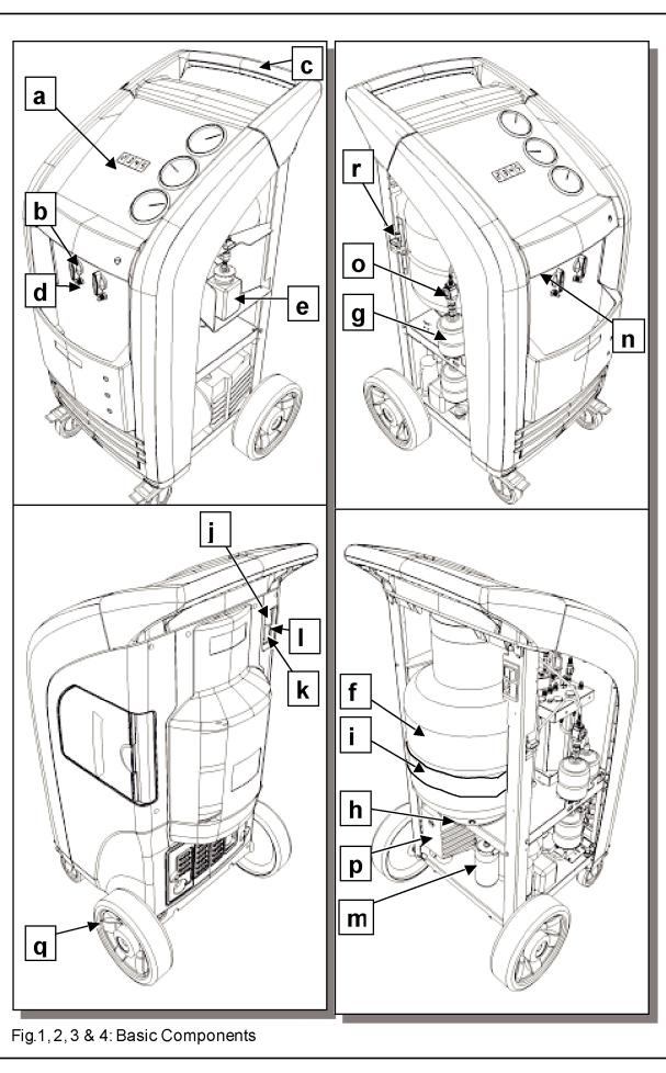
Refer to fig 1, 2, 3 & 4:
a) |
Control Console |
b) |
Valves |
c) |
Handle |
d) |
High/Low Pressure Threaded Connectors |
e) |
New Oil Container |
f) |
Storage Tank |
g) |
Desiccant Filters |
h) |
Electronic Scale |
i) |
Heater Blanket |
j) |
Main Power Switch |
k) |
Socket for Electrical SupplyPlug |
l) |
Fuse |
m) Used Oil Container |
n) |
Serial Port |
|
o) |
Moisture Indicator |
p) |
Vacuum Pump |
q) |
Wheels |
r) |
Air Purge Valve |
8
9
INSTRUCTIONS MANUAL
CONTROLS AND CONTROL SYSTEM
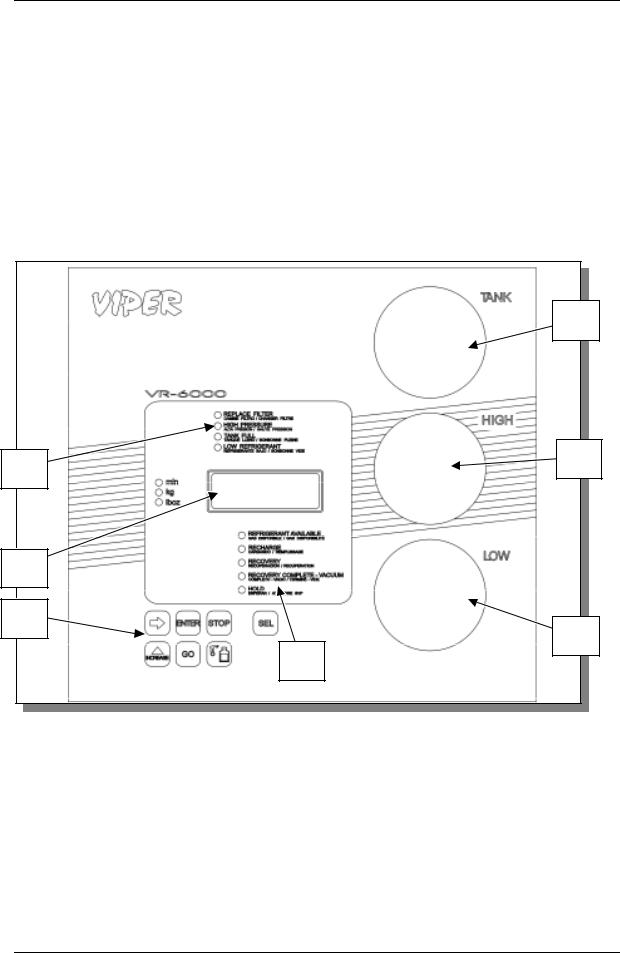
Refer to Fig 5:
(A1) Low pressure gauge for A/C system
(A2) High pressure gauge for A/C system
(A4) Pressure gauge for storage tank
(A6) Emergency/alarms panel
(A7) Display
(A8) Keypad controls
(A9) Operations selector panel
A4
A6 |
A2 |
|
A7
A8
A1
A9
Fig.5: Control Panel
10
INSTRUCTIONS MANUAL
FUNCTION SELECTOR KEYBOARD
Refer to Fig 6:
(T1) REFRIGERANT AVAILABLE LED indicator: when lit, the display reports the weight of the available refrigerant in the storage tank.
(T2) RECHARGE LED indicator (flashes during the CHARGING phase). (T3) RECOVERY LED indicator (flashes during the RECOVERY phase). (T4) EVACUATE LED indicator (flashes during the VACUUMphase).
(T5) HOLD: flashes at the end of the recovery during the OIL DISCHARGE phase.
(T6) SEL key: Selects the operation to be performed. Every time this key is pressed one of the LEDs from T1 through T4 will light in sequence; the LED alongside each operation indicates that the operation maybe started or that it is being performed (flashing LED).
(T7) INCREASE key: Each time this key is pressed during the operations relative to setting the time and the quantity, the value of the flashing digit on the display will be increased byone unit.
(T8) ARROW key: Each time this key is pressed while a display value is flashing during the operations relative to setting the time and the quantity, a different digit will be selected for modification (selected digit will flash).
(T9) ENTER key: Pressing this key when a LED corresponding to an operation is lit but not flashing will permit modifying the evacuation time, and desired charging weight. After setting the desired value press the keyagain to complete the process.
(T10) GO key: Pressing this keywill start the operation indicated bythe lighted LED (T11) STOP key: Pressing this keywill stop the operation indicated bythe flashing LED.
(T12) °F key: Pressing this keythe displaywill show the bottle temperature in Celsius degree
11
INSTRUCTIONS MANUAL
or Fahrenheit degree.
(T13) Display: According to the operation selected, displays the evacuation time, tank temperature, or weight of available refrigerant.
STATUS AND ALARM PANEL
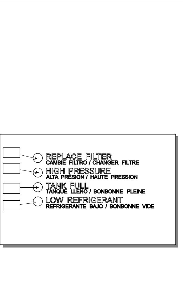
See Fig 7:
(C1) REPLACE FILTER: the Low side refrigerant filter/dryer must be changed when the led “REPLACE FILTER” lights up. When recovering new refrigerant this light may come on prematurely. It maybe reset bypressing the SEL keywhile turning on the machine.
(C2) HIGH PRESSURE: Lights and emits an acoustic signal when the pressure of the fluid in the circuit exceeds 290 psi (20 bar). The RECOVERY operation is automatically interrupted. This will occur if you attempt to recover refrigerant with the tank valves closed, and will require some disassembly to reset (see TROUBLE SHOOTING section)
(C3) TANK FULL: Lights and emits an acoustic signal when the bottle is filled to more than 80% of maximum capacity, approximately 40 lbs. The RECOVERY operation is automatically interrupted. You may use the CHARGING function to remove refrigerant from the storage tank.
(C4) LOW REFRIGERANT: Lights and emits an acoustic signal when the quantity of refrigerant fluid contained in the bottle is low, near 4 lbs (~2 kg). You will need to add additional refrigerant to continue with a CHARGING function.
C1
C2
C3
C4
Fig.7: Front views
12

INSTRUCTIONS MANUAL
MEASUREMENT SETTING
When power is turned on to your new VIPER VR-6000, the keypad display will show the gas weight in the service tank. The display can be set to read in either metric or standard measurements, proceed as follows:
•Switch off the VR-6000.
•Press the SEL, GO, and ENTER keys simultaneously while turning on the VR-6000. The machine will change from one system of units of measurement to the other.
VIPER VR-6000 SPECIFICATIONS
Electrical Input: |
115 Vac, 8 A, 60 Hz |
Ambient Operating Temperature Range: |
50° F (10° C) to 120° F (48.9° C) |
Approximate Shipping Weights: |
170 lbs. |
PREPARATION FOR USE
GENERAL
Your VIPER VR-6000 Air Conditioning Service Center is shipped completely assembled and 100% pre-tested. Your VIPER VR-6000 needs to be prepared before it can be used to service a vehicle's air conditioning system.
PREPARATION
The following steps, for the most part, are used only to prepare your VR-6000 for operation.
1.Remove the shipping carton.
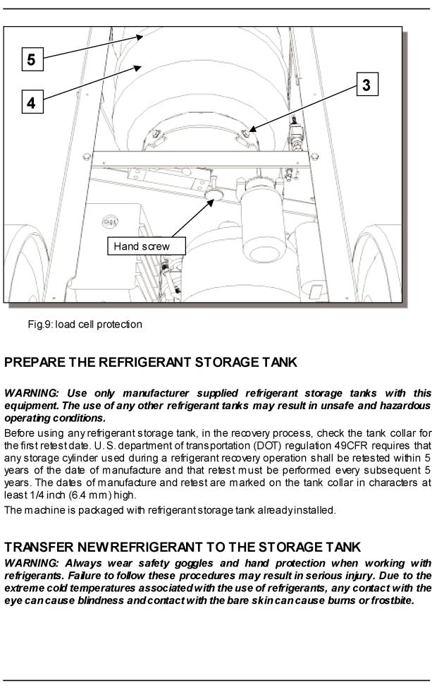
2.Lift out the VR-6000 from the pallet to the ground.
3.Loosen the scale hand screw (see Figure 9) that is under the scale platform. It is tightened to prevent damage to the scale during shipment. Turn counter clockwise six full turns. Note: If you do not loosen the scale hand screw under the scale platform, the scale will remain inoperable.
13
14

15

INSTRUCTIONS MANUAL
OPERATION INSTRUCTIONS
RECOVER AND RECYCLE REFRIGERANT FROM AN AC SYSTEM
1.Be sure that the shut off valves are off prior to attaching to a vehicle AC system.
2.Attach the machine to the high and low sides of the AC system to be serviced. The R- 134a hoses have SAE approved shut-off valves (quick disconnects). The hoses are shut off when disconnected from the AC system and are open only when connected with the knurled knobs turned clockwise. Slide the collar of the fitting back and press to the appropriate fitting.
•Blue hose to the low side of AC system
•Red hose to the high side of AC system
3.Set MAIN POWER (k, Figure 3) ON.
4.Open the valves on the service hoses by turning the knurled knob clockwise (Figure 12). This will allow refrigerant to flow to the vehicle.
5.Observe the pressure readings on the low and high side manifold gauges. If the readings are zero, then repair AC system leak or proceed to vacuum phase.
6.Open the High Side and Low Side valves on the control panel of the machine.
7.Press and hold the SEL key until the LED corresponding to “RECOVERY” lights; then press GO. At this point the RECOVERY/RECYCLING phase will begin and the “Recovery” LED will flash.
8.During the RECOVERY/RECYCLING phase the amount of refrigerant recovered from the vehicle will be displayed. Upon completion of the recovery phase the machine will stop and hold three minutes.
9.During this time the machine automatically discharges the used oil. It will be necessary to monitor this oil dumping to determine the amount of oil that must be added to the vehicle. When the oil discharge is complete, measure, record and empty the oil discharge bottle. This amount will be added to the AC system before charging. When there is no increase in system pressure, the vacuum pump will start and evacuate the input oil separator inside the VR-6000.
10.If, during this 3-minute time period, the residual refrigerant left in the A/C system causes the pressure to increase, the machine will automatically resume recovering the refrigerant. When this phase is complete the machine will sound and audible alarm, and switch to the REFRIGERANT AVAILABLE display.
11.Close the High Side and Low Side panel valves.
12.Set the MAIN POWER switch OFF.
13.Disconnect the machine if desired. (See DISCONNECTING THE MACHINE FROM A VEHICLE.)
14.Make necessary repairs to the A/C system being serviced.
REMOVING NON-CONDENSABLE GASES
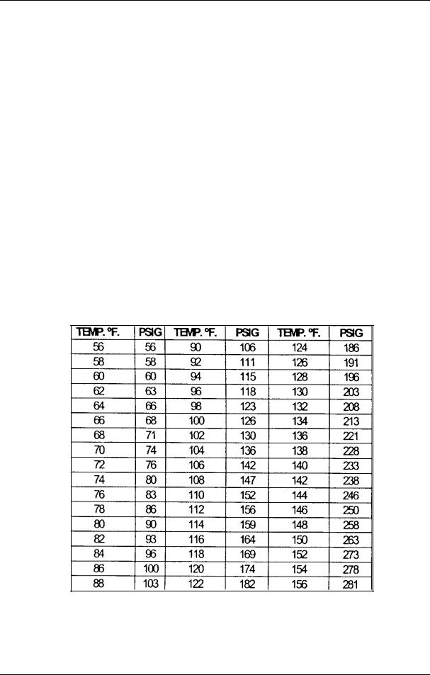
As non-condensable gases accumulate in the refrigerant storage tank, excessive pressure is created. The most noticeable symptom of excess pressure is a slow down of refrigerant flow during the recovery process. In most cases, you will not notice a reduction in refrigerant recovery rate until the nominal pressure in the storage tank is 20 psig above the normal pressure, as listed on the purge chart. Check for non-condensable gases after each recovery phase. The table provided below (Figure 13) is used to determine when an excess of non-condensable gases has accumulated in the refrigerant storage tank.
16
INSTRUCTIONS MANUAL
Proceed as follows:
“REFRIGERANT AVAILABLE” LED must light, if it is necessary press the SEL key to switch the light to “REFRIGERANT AVAILABLE” LED.
1.Press once the “°F” key in order to display the refrigerant tank temperature (in Fahrenheit degree), press it a second time to display the temperature in Celsius degree)
2.Read the storage tank pressure of the tank gauge
3.Find the temperature in the TEMP °F column for that tank then read the associated PRESSURE column in psig.
4.If the related TANK PRESSURE gauge (A4, fig.5) reads LOWER or EQUAL than the nominal pressure listed in the table for the respective tank temperature, IT IS NOT NECESSARY to vent the non-condensable gases from the tank.
5.If the related TANK PRESSURE gauge (A4, fig.5) reads HIGHER than the nominal pressure listed in the table for the respective tank temperature, you should vent the non-condensable gases from the tank. This is accomplished by opening the air purge valve as shown in figures 1,2,3, & 4.
6.Press the STOP keyto exit the reading of the tank temperature
7.Slowlyopen the air purge valve (r,fig.2) counterclockwise (turn ~20 degree)
8.Once opened the air purge valve r, (fig.2) check the tank pressure gauge and the value shown bythe display.
9.Close the air purge valve when the tank pressure comes down to the nominal pressure listed in the table.
Fig.13: Normal R-134° container pressure chart
17

INSTRUCTIONS MANUAL
VACUUM PHASE
1.Upon completion of the RECOVERY phase it is possible to start the vacuum phase by opening the highand low-pressure valves, pressing the SEL key until the LED corresponding to “EVACUATE” lights, and then pressing GO. The vacuum time can be set as follows. Press SEL until the “EVACUATE” LED lights, then press ENTER; at this point the first digit on the left of the displaywill begin to flash. Press the INCREASE key until the desired digit appears. Likewise, press the ARROW and INCREASE keys to change the other digits. When setting is complete, press the ENTER key to confirm the vacuum time value.
2.During the vacuum phase, the display will clock its duration. Leave the machine running until the displayreads 0000 and the pump stops automatically.
3.Close all the valves and read the vacuum value on pressure gauges (A1) and (A2). Wait for about 2 minutes, and then check that the pressure has not increased during the interval. An increase in pressure signals leaks in the A/C system. Locate and eliminate the leaks; repeat the vacuum phase.
WARNING: Avoid breathing A/C refrigerant and lubricant vapor mist. Exposure may irritate eyes, nose, and throat. To remove HFC-134a from the A/C system, use service equipment certified to meet the requirements of SAE J2210 (HFC-134a recycling equipment). Additional health and safety information may be obtained from additional refrigerant and lubricant manufacturers.
NEW OIL INJECTION
You can inject virgin lubricating oil into the vehicle A/C system at this time. Make certain that the Oil Charge Bottle has sufficient quantity of oil. Cautiously open the Oil Charge valve until the same amount of oil that was recovered in the RECOVERY AND RECYCLING operation is removed from the container and replaced back into the vehicle's A/C system. The oil will be drawn into the vehicle A/C system by the deep vacuum that was obtained while evacuating. The subsequent charging of refrigerant will ensure all of the oil will be charged from the lines and hoses.
RECHARGE AN A/C SYSTEM
WARNING: Always wear safety goggles and hand protection when working with refrigerants. Failure to follow these procedures may result in serious injury. Due to the extreme cold temperatures associated with the use of refrigerants, any contact with the eye can cause blindness and contact with the bare skin can cause burns or frostbite.
CAUTION: When charging a vehicle do not lean on the machine as this may affect the scale readings. Inaccurate weight measurements may result. The vehicle system can be damaged if weights are not measured accurately.
During this phase, the correct refrigerant charge is returned to the vehicle’s A/C system.
1.Press the SEL keyuntil the “RECHARGE” LED lights.
2.Proceed as described below to set the quantity of refrigerant fluid to be charged. Press the ENTER key. The first digit on the left of the display will begin to flash. Press the INCREASE keyuntil the desired value appears. (Digits read in pounds and ounces, or kilograms.) Likewise, press the ARROW and INCREASE keys to change the values of the other digits. Press ENTER when setting is completed to confirm the values. The quantity of fluid required for filling the system is usually reported on a data plate in the engine compartment of the vehicle. If the quantity is not known, consult the relevant system operating and maintenance manuals.
18

INSTRUCTIONS MANUAL
3.Open the highand low-pressure valves (if previouslyclosed) and press the GO key.
4.The machine will stop automatically when the preset quantity has been charged. If the A/C system pressure increases to equal the tank pressure, and the charge is not complete, it will be necessary to draw the remaining refrigerant into the system using the vehicle compressor as outlined below.
5.Close the highand low-pressure valves.
6.Start the vehicle motor and switch on the A/C system, and allow both to run for at least 3 minutes. At this point the system will be at steady state and it will be possible to check the high and low side values on the relative pressure gauges.
7.Disconnect ONLY the high-pressure quick-connect coupling (if necessary, switch the engine off). Then, with the A/C system still running, open the high and low pressure taps to force the A/C system to draw up the refrigerant contained in the hoses.
8.After about 1 (one) minute, disconnect the low-pressure couplings of the VIPER VR6000 from the vehicle A/C system and switch off the engine.
WARNING: When removing hoses from the vehicle, use extreme caution. Wear gloves and eye protection. Take care not to allow refrigerant to enter the eyes. Liquid refrigerant will cause severe burns and/or frostbite to exposed skin, blindness if sprayed into the eyes, and even the possibility of death if inhaled.
RECOVERING THE REFRIGERANT IN THE HOSES.
1.Set the MAIN POWER switch ON and open the high side and low side valves on the front of the machine.
2.Press and hold the SEL keyuntil the LED until the LED corresponding to “RECOVERY” lights; then press GO. At this point the RECOVERY/RECYCLING phase will begin; the “RECOVERY” LED will flash.
3.When all of the refrigerant has been removed from the hoses, the machine will automatically shut off and the lamp in the switch will extinguish. To avoid going through an “unnecessary and time consuming oil dumping phase”, press the stop keyas soon as pressure in low pressure hose reaches zero.
4.Close the High Side Valve and Low Side Valve and turn off the machine’s main power.
19
INSTRUCTIONS MANUAL
MAINTENANCE
REPLACING REFRIGERANT FILTER/DRYER
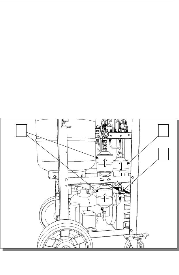
The VIPER VR-6000 is equipped with two high side refrigerant filters/dryers and a low side refrigerant filter/dryer (see figure 14). In order to maintain high qualityrecycled refrigerant:
•The low side refrigerant filter/dryer must be changed when the VR-6000 displays the service alarm [SERV] and the led “REPLACE FILTER” lights up.
NOTE: When recovering new refrigerant as when the machine is first placed in service this alarm will light abnormally early and may be cleared by pressing the “SEL” key while turning on the machine.
•The high-pressure refrigerant filters/dryers must be replaced after approximately 30 hours of operation or 150 service jobs.
ATTENTION: Use only |
Clore Automotive Filters Part No. 315-032-000 (Low) |
and Part No. 315-035-666 |
(High). |
When changing the high pressure filters it is recommended that you disconnect the liquid hose from the storage tank (close the hose valve and the liquid tank valve first), and recover the refrigerant from the machine with another machine through the liquid hose. Then proceed as described below:
1 |
2 |
|
3 |
Fig.14: Dryer filters
20
INSTRUCTIONS MANUAL
If the high and low gauges indicate positive pressure, then recover the refrigerant in the hoses back into the storage tank.
1.Disconnect the machine from main power supply.
2.Put on gloves and safetygoggles.
3.Remove the rear plastic cover.
4.Close the valves on the storage tank.
5.Close the L.P. filter-tap. (3)
6.Working slowlyand carefully, unscrew the couplings at the inlet and outlet to the filters.
7.Loosen the filter clamps.
8.Replace the filters, taking care to insert them in the correct direction. (1,2)
9.Tighten the clamps and the couplings at the inlet and outlet to the filters.
10.Open the valves on the storage tank.
11.Open the L.P. filter-tap. (3)
12.Replace the rear plastic cover.
13.Reconnect and switch on the MACHINE.
14.During the first 10 seconds (when the service alarm [SERV] is displayed), press the SEL key.
15.Type in the filter code 0014 to cancel the alarm (use the INCREASE and ARROW keys).
16.Charge and recover about 8 oz. of refrigerant to charge the machine circuit.
17.Switch off the MACHINE
18.Disconnect the machine from main power supply.
CAUTION: Replace the old filter with the new one as quickly as possible in order to avoid possible contamination with the humidity in the ambient air.
EMPTYING THE USED OIL TANK
This operation must be performed after every recovery.
Procedure: remove the tank from its lodging and unscrew the cap; empty the tank into a container for used oils, Replace the cap and replace the container in its lodging.
CASE CARE
If the case of the unit becomes soiled, clean with a mild detergent and a clean rag. Do not use solvents – some solvents maycause a deterioration of the material and harm your A/C Service Center.
AIR CONDITIONING HOSE MAINTENANCE
The manufacturer recommends that the hose seals be checked periodically and replaced at the beginning of each season, at minimum. Contact your local distributor when replacement seals are needed.
CALIBRATING THE ELECTRONIC SCALE
This operation should be performed when the scale values displayed are out of line with known values. The operations listed below must be performed with the maximum attention and care. Always observe the precautions outlined in this section. Always place the weights carefully on the scale plate, one at a time. Always place the weights the center of the scale plate. Proceed as explained below to calibrate the scale (see fig. 1, 2, 3, & 4). Disconnect the machine from main power supply. Procure a known reference weight (50 lbs). Remove the plastic cover on the rear of the machine to access the machine bottle. Close the blue and red valves on the storage tank. Remove the storage tank locking bolts. Separate the heater
21

INSTRUCTIONS MANUAL
blanket (i) from the storage tank (do not touch or disconnect the wires of the heater blanket).
Extreme care must be taken when removing the storage tank, so as to avoid pulling wires loose and damaging the copper tubing.
Remove the storage tank (f) from its seat, leaving the heater blanket around the scale plate. Rest the storage tank on a stand at least 10” in height. Switch on the MACHINE. Be careful not to touch any electrical wires. Wait at least 10 seconds and press STOP to silence the alarm. Press the INCREASE and ARROW keys simultaneously and hold down for about 5 seconds. The value displayed at this point will correspond to the scale zero value. Press down lightlyon the scale plate; the value should increase. If it does not, replace the charge cell. Press the ENTER key to memorize the value. In this phase, take care that nothing touches the scale plate). Place the reference weight (50 lbs) carefully at the center of the scale plate and check that the displayed value increases accordingly. Press the SEL keyand use the INCREASE & ARROW keys to type in the 4 figures of the reference weight. Press ENTER. The display reading should be the reference weight minus the weight of the empty bottle (tare weight).
Remove the reference weight. Switch off the machine and disconnect from main power supply. Replace the storage tank in its seat on the scale plate. Switch on the MACHINE, taking care not to touch any electrical wires. Check calibration: place a known reference weight on the bottle and check that the displayed availability value increases by the value of the known reference weight ±2%. Remove the reference weight. Switch off the machine and disconnect from main supply. Replace the storage tank locking bolts. Open the red and blue storage tank valves. Replace the rear plastic cover.
NOTE: In order to check the scale calibration the unit must be displaying a positive value for REFRIGERANT AVAILABLE, if the display is reading zero additional weight must be added to the top of the tank to get a positive reading. The known weight is then added and the change in weight is verified as the known weight.
VACUUM PUMP
Perform the operations listed below on a routine basis in order to ensure good operation of the vacuum pump.
M.1) Oil top-up
M.2) Oil change
M.3) Decontamination
When topping-up or replacing the pump oil, use only VIPER No. 793091 Vacuum Pump Oil.
M.1) Oil top-up
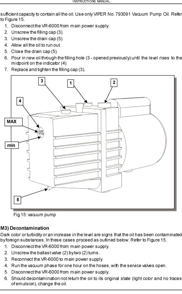
This operation must be performed when the level of the oil falls to less than half on the indicator (4 - Figure 15). To refill the oil, perform the steps listed below in the order given. Refer to Figure 13.
1.Disconnect the VR-6000 from main power supply.
2.Unscrew the filling cap (3).
3.Pour oil into the tank until the oil level is about half on the indicator (4).
4.Replace the oil cap (3) and tighten down.
M.2) Oil change
The vacuum pump oil must be replaced once a season and in any case every time the refrigerant filters are replaced. The oil must also be changed whenever it changes color, becoming dark and turbid, since this is a sign that it has been contaminated and has absorbed humidity. Before beginning the oil change procedure, procure a container of
22
23
 Loading...